M2M Easy 2 User manual

M2M Easy 2
Security Communicator®
Installation Guide
for firmware v2.1 R08
_____________________________________
Rev: 2.2
2017-02-09

2
Document specifications
This documentation was compiled for the
M2M Easy 2 Security Communicator
®with the
SW v2.1 R08 or newer versions, which were developed by
WM Systems LLC.
, and contains the
step-by-step description of its installation, the program update process and the detailed
introduction of the setup parameters necessary for its operation.
Document Type:
Installation Guide for v2.1 R08
Device:
M2M Easy 2 Security Communicator
Author:
Tóth Csaba, Benyhe Tamás, Tóth
Zoltán, Horváth Attila Tamás (WM
Systems LLC.)
Contact:
Email: csaba.toth@m2mserver.com
Checked by:
Tóth Zoltán, Kim Balázs, Horváth Attila
Tamás
Document revision:
REV 2.2
Pages:
85
Hardver version:
v8.21
Firmware version:
V2.1 R08
Bootloader version:
REV 0.95
EasyTerm Software version:
REV 1.3.1 2017.01.19.
Document Status:
Final
Availibilty:
Public
Made at:
2nd of July, 2014.
Last Modification:
9nd of Februar, 2017.
Valid from:
9nd of Februar, 2017.

Table of Contents
1. Connecting the ports ......................................................................................4
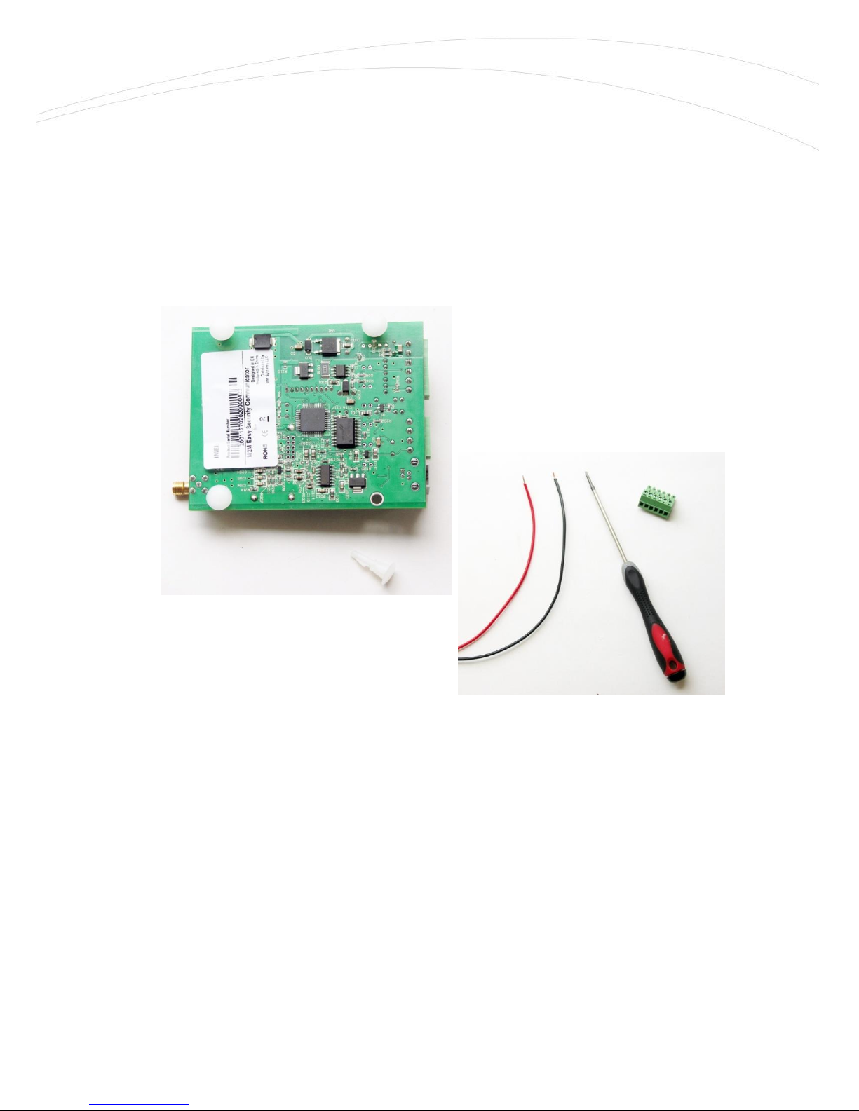
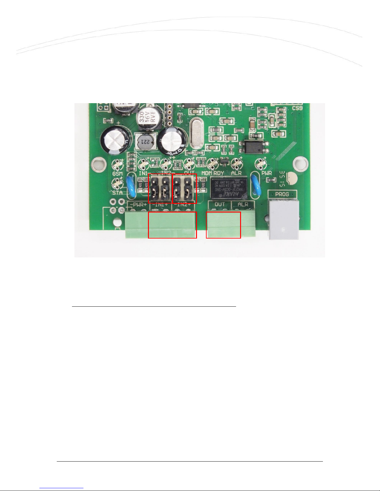
1.1 Connecting/wiring possibilities................................................................................................4
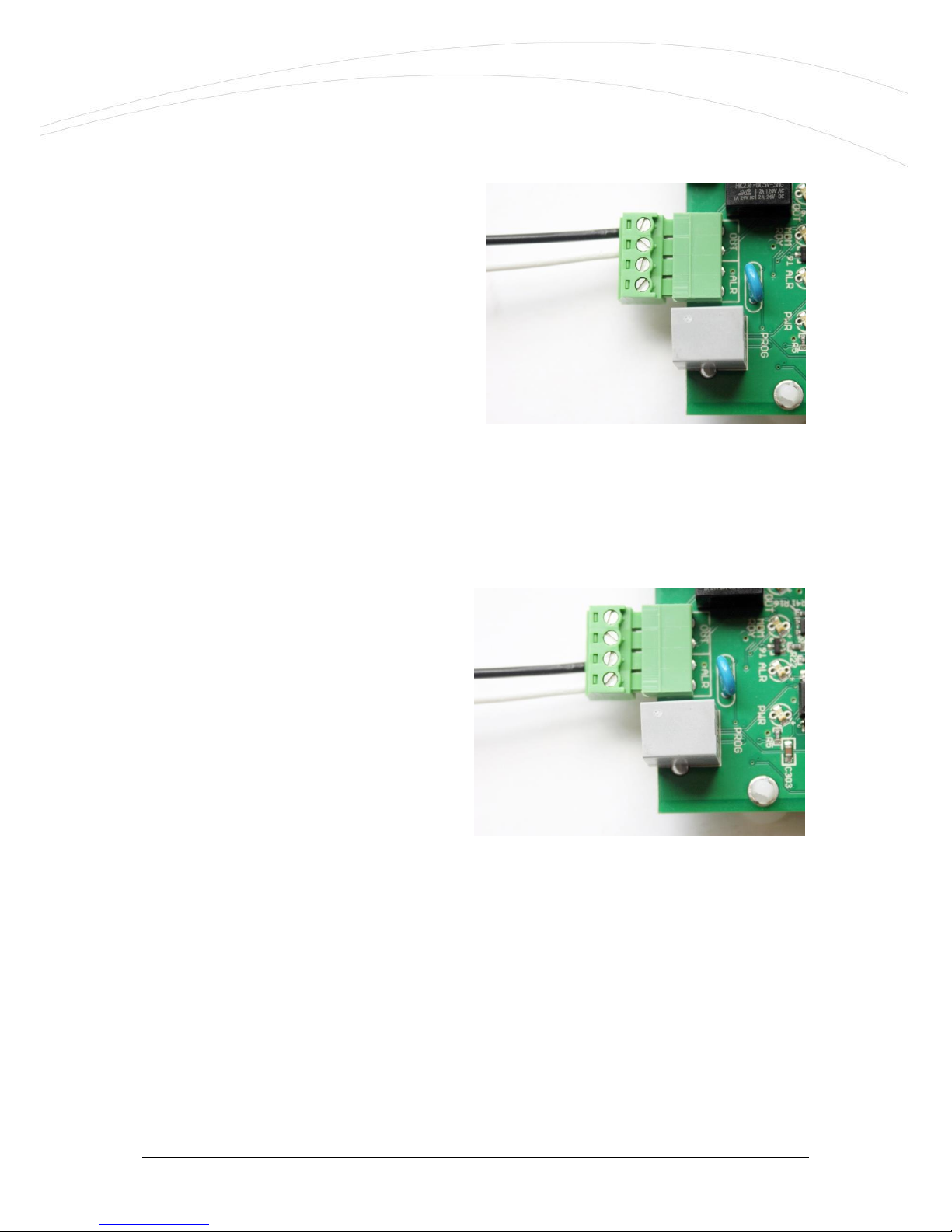
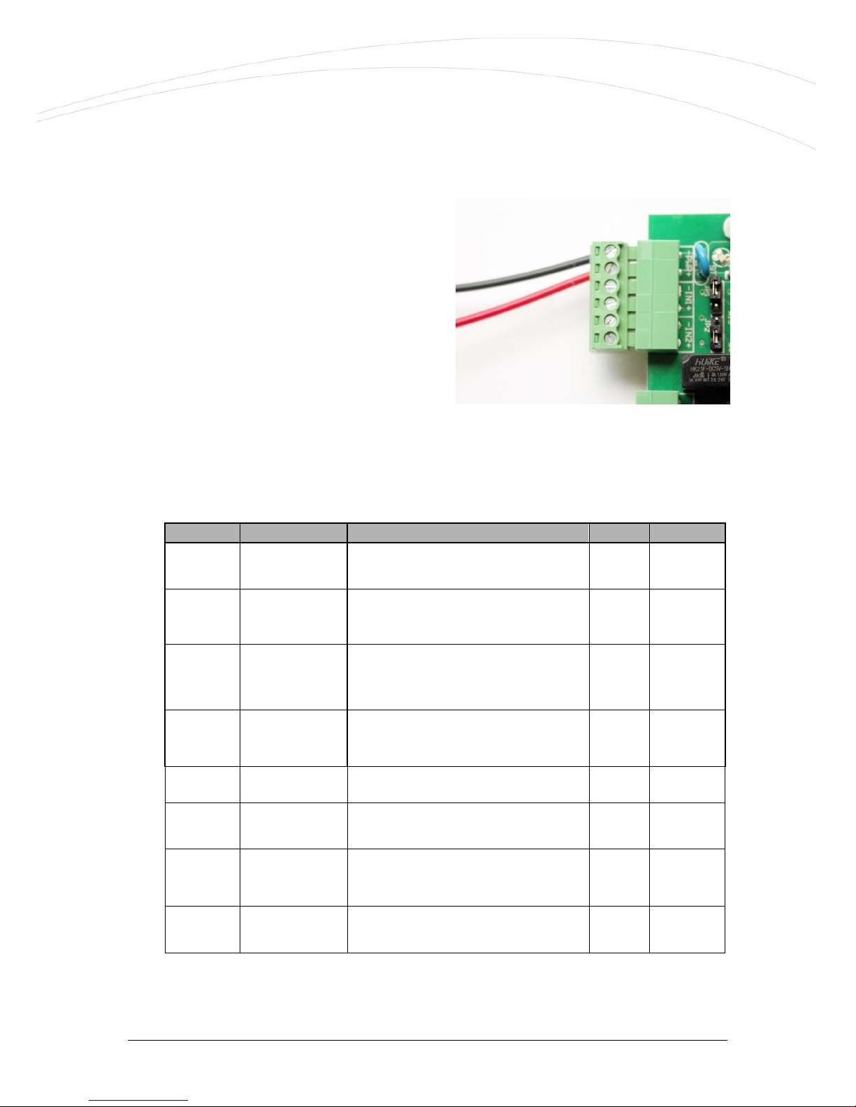
1.2 Wiring .................................................................................................................................6
1.3 LED signals......................................................................................................................... 10
1.4 Operation requirements....................................................................................................... 14
2. Installation of the device .............................................................................16
2.1 Installation on location site .................................................................................................. 16
2.2 Turning on the device ......................................................................................................... 17
3. Connecting the device to a computer ...........................................................19
3.1 Required software components ............................................................................................ 19
3.2 Connecting with a computer................................................................................................. 20
4. EasyTerm (configuration, software refresh) .................................................21
4.1 Introducing the EasyTerm tool ............................................................................................. 21
4.2 Connecting to the device ..................................................................................................... 22
4.3 Status and device data ........................................................................................................ 25
4.4 Terminal window, communication messages.......................................................................... 26
4.5 File handling....................................................................................................................... 26
4.6 Contact list for output control and gate opening..................................................................... 28
4.7 Firmware upload/refresh...................................................................................................... 30
4.8 Device restart ..................................................................................................................... 33
4.9 Factory default settings ....................................................................................................... 33
4.10 Manual arming.................................................................................................................. 34
4.11 Gate opening .................................................................................................................... 34
4.12 Disabling zones (Bypass mode) .......................................................................................... 35
5. Configuring the Easy 2 ................................................................................37
5.1 GSM transmitter settings...................................................................................................... 37
5.2 Transmitting to Enigma IP-receiver (Settings)........................................................................ 39
5.3 GPRS transmitting settings................................................................................................... 43
5.4 Standalone Alarm System mode settings ............................................................................... 50
5.5 Monitoring input lines and gate opening settings.................................................................... 60
5.6 Further safety settings......................................................................................................... 66
5.7 Firmware update/refresh from FTP server ............................................................................. 68

4
6. Further information about operation of the Easy 2 ......................................70
6.1 Primary and secondary communication channel ..................................................................... 70
6.2 Using the secondary channel................................................................................................ 70
6.3 Signalling by GSM call.......................................................................................................... 71
6.4 Receiving the signalling of events ......................................................................................... 71
6.5 Life signals ......................................................................................................................... 71
6.6 Voice call notification (ringing) ............................................................................................. 72
6.7 Gate opening...................................................................................................................... 72
7. Configuration by SMS messages ...................................................................73
7.1 Authentication command ..................................................................................................... 73
7.2 Query commands................................................................................................................ 75
7.3 Parametrizing by commands ................................................................................................ 75
7.4 Examples for SMS command parameters............................................................................... 77
8. CID code table .............................................................................................80
9. Troubleshooting ...........................................................................................82
9.1 A failure signed by the LED flashing ..................................................................................... 82
9.2 Signing the status and signal strength problems .................................................................... 83
10. Support availability .....................................................................................86
10.1 Support help..................................................................................................................... 86
10.2 Product support ................................................................................................................ 87
11. Legal notice ................................................................................................88

5
Chapter 1. Connecting the ports
4.12
Connecting/wiring possibilities
Input, output connections
1 –SIM-card holder (push-insert)
2 –SMA antenna connector (GSM/GPRS antenna, 50 Ohm)
3 –PWR +/-: Power supply connector (8-24VDC, min. 800mA)
4 –IN1, IN2: 2pcs connector for input lines (for sensors, sabotage)
5 –Jumpers for the input lines (IN1, IN2) to select the operation mode (voltage, contact
(cut or short))
6 –OUT: 1pc relay output (for switching a siren/bark)
7 –ALR: Alarm line (TIP RING input (for alarm center analogue phone line connection)
8 –PROG: RJ11 connector (for configuration, software upload) for RJ11-RS232 cable
9 –Expansion board connector (used in case of applying the
Easy 2 IO
expander)

6
1.2 Wiring
Preparation
Take the 4 spacer fixing tabs provided with the device, and place them into the PCB holes as
shown in the picture.
Prepare a screwdriver, the 2 terminal blocks
provided with the device, and the stripped
wire pair necessary for connection, with
appropriate distinctive colors (power
connector –e.g. black-red, input-output wire
pairs –e.g. black-blue, alarm input –e.g.
black-white).
Connecting the inputs
The device has 2 input lines (IN1, IN2),
where sensors can be connected by connecting its wire pairs, in accordance with the standard
connection method shown below, by fixing the cable wire pairs for each input.
In case of voltage inputs make attention to the order of polarity (+/-), the assembly must be
done according to the inputs line titles (on PCB board). Take care for the proper position of the
input line jumpers.
The device is able to detect wire cut on its input lines.
The inputs may also be used for anti-sabotage purposes –e.g detecting/monitoring the
opening of the alarm system cover (magnetic switch).

7
In voltage input operation mode, the input lines can be activated with 5-24V DC voltage, in
opposite way these are inactive.
The proper operation mode can be configured as well with the
EasyTerm
application.
These can be configured seperately to operate as a voltage or contact mode for the input.
These settings can be setup with the jumpers besides the terminal blocks of the input lines –
according to the input line nr. titles.
Choosable input line operation modes (with the jumpers):
Contact mode
oThe input line jumper pairs - approach from the connector side
oThe ground point of the input lines (-) are common
oThe wiring of input lines has independent polarity
Voltage mode
oThe input line jumper pairs –approach from the LED’s side
oGalvanically divided and independent input lines
oMake attention to the polarity when wiring!
INPUTS
(IN1, IN2)
OUTPUT
(OUT)
IN2
IN1

8
Signal levels:
Input high signal level: 5-24V
Input low signal level: 0-1V
Current in active status (for the Easy 2 inputs): 0.3-3mA
Current in active status (for the further Easy 2 IO inputs): 1-12mA
In case of using the
Easy 2 IO
-expander board, further 6 pcs of inputs are available (IN3..IN8),
which has the same operation and configuration possibility as listed here above.
When the input were activated (IN1, IN2) the IN1, IN2 titled LEDs are signing the active
(closed) status during the operation, with the proper light and colour. See LED signals part.
The device has 2 input lines (IN1, IN2). They can be configured seperately to operate as a
voltage or contact mode for the input. These settings can be setup with the jumpers besides
the IN1, IN2 input line’s terminal blocks.
Connecting the relay output
One switchable output device can be connected to the relay output (OUT) of the mainboard),
according to the next figure. Connect the cable wire pair to the OUT title output line’s terminal
block (by sliding the companion piece and inserting the stripped wire pair, then fixing the
screws).
Mode
Contact
Voltage
Not inverted
NO (Normal Open)
Inactive mode: contact
opened
Active mode: contact closed
High active
Inactive mode: 0…1V
Active mode: 5…24V
Inverted
NC (Normal Closed)
Inactive mode: contact closed
Active mode: contact opened
Low active
Inactive mode: 5…24V
Active mode: 0…1V

9
Through the relay output a 2A - 120VAC or
2A - 24VDC voltage can be switched. When
activating the output, the OUT LED –
beside the output - indicates the active
(closed) position with the appropriate
color/light - during the operation.
ATTENTION
Always switch off power supply before the
wiring!
Check that the metal parts of the connected wires are not touch to each other!
Connecting the alarm line ( ALARM line)
The alarm system can be connected to
the ALR input through a wire pair, thus it
will be able to forward its alarm signals –
in Contact ID format –to the remote
dispatcher centre.
Connect the cable wire pair to the ALR
title Alarm line’s terminal block (by sliding
the companion piece and inserting the
stripped wire pair, then fixing the screws).
When activating the output, the ALR LED
–beside the output - indicates the active (closed) position with the appropriate color/light -
during the operation.
Inserting the M2M Easy 2 IO board (optional)
The
M2M
Easy 2 Security Communicator®
firmware can handle the operation of the
IO-
expander
board
(extra 6 pcs of inputs, 3pcs of outputs), whereas further parameters are
available in the device software and in the
EasyTerm
configuration tool.

10
Connecting the power supply
The 8-24V power-supply voltage (typically 12V
power adapter, or 24V power supply) can be
connected to the PWR input through a wire
pair. When connecting the power, the device
will be immediately started to operating, when
the PWR LED will indicate it with the
appropriate color/light.
Attention! Do not forget to insert the
SIM-card previously –see Chapter nr. 2.
1.3 LED signals
The status LEDs are helping to understand the current operation of the device.
LED
Function
Description
LED
státusza
Behaviour
GSM
GSM receiving
signal strenght
Signing the available signal strenght –more
flashes = better signal strenght
red
flashing
STA
GPRS modem
status
In case of normal operation it signs the GPRS
communication status
See the detailed description ot STA LED part
yellow
flashing
/lights
IN1
Input #1 signal
Signs the status of the #1 input line (I1INV
or IDELAY parameters are applied)
lights if the input wires are closed (active)
green
lights
IN2
Input #2 signal
Signs the status of the #2 input line (I2INV
or IDELAY parameters are applied)
lights if the input wires are closed (active)
green
lights
OUT
Output relay
signal
Lights: relay closed, not lights: relay opened
yellow
lights
MDM RDY
Modem operation
Modem status. Flashes intermittently if the
modem operates and accessible.
red
flashing
ALR
Alarm center
signal
Status of the alarm center line (Tip-Ring),
signs: speaker on, not lights: speaker off or
no alarm center presented
green
flashing
PWR
Operation
Signs the presence of the processor power
supply (3,3V)
green
lights

11
GSM: GSM/GPRS status LED - red
The numbers of the GSM LED flashing sequence signs the curent RSSI signal strength og the
GSM module (more flashes are meaning a better signal reception).
There is 10 seconds between the flash signals. One flashing takes 50 msec, then half a second
breaking continues.
RSSI value
(AT+CSQ)
GSM receiving signal
strength
LED flashing (GSM)
99
unknown, faulty value
0
0..7
-113 dBm.. -99 dBm
1
8…11
-97… -91 dBm
2
12..15
-89… -83 dBm
3
16…19
-81… -75 dBm
4
20…23
-73… -67 dBm
5
24…27
-65… -59 dBm
6
28…31
-57… -51 dBm
7
STA: Status LED - yellow
The STA LED assures information about the current operation. It has 3 modes:
It twill be active only if the GPRS signal transmission permitted. In this case from the beginning
of the signal transmission the LED starts to flashing.
lights continuously: the last GPRS signalling was succesful
with 3 second of breaks * nr. of flashing (the light interval period is half a seconds),
failure code (see later)
Turned off: GSM operation mode, no error
Filure codes –for signing the device opreation troubles –in case of a failure, read the
Chapter nr. 9!
1 flash - Module failure
The serial connection is not operating properly between the module and the
Easy 2
board. After 1 minute, the device automatically tries to restart the module.

12
2 flashing - SIM card failure
Possible reasons:
othere is no SIM card inserted
oSIM card pinpad contact error
The device in this status will not continues its initialization, the receiving of serial port
commands is still active (for parametrizing). After 1 minute, the device automatically
tries to restart the module.
3 flashing - PIN authentication failure
Possible reasons:
owrong PIN code
oPUK code (security code) is necessary to give in
The device in this status will not continues its initialization, the receiving of serial port
commands is still active (for parametrizing). After 5 minutes, the device automatically
tries to restart the module.
4 flashing –The device cannot login to the GSM network
A hibajelzés a hálózati regisztráció alatt, vagy a GSM hálózatról való leszakadáskor
azonnal aktiválódik. Ha a hiba 5 percig folyamatosan fennáll, az eszköz automatikusan
újraindítja a modult.
5 flashing –the GPRS is allowed (GPRSEN=1), but the device cannot login to the
GPRS network
Possible reasons:
owrong APN settings
othe GPRS service is inactive for the SIM card
olow signal strength
othe RADIUS server is out of operation
omaintenance/service tasks by the M.O.

13
6 blinkings –the device is registered to the GPRS network, it has an IP address, but
cannot login to the server
Possible reason: the primary and the secondary server is not available/accessable
Visible sympthoms:
the opening of the TCP/UDP port was not succesful (e.g. wrong server
settings applied),
unsuccesful data sending
timeout when tries to receive data or wrong answer
The signal will be active, until the device will be succesfully signalling to a server.
IN1, IN2: Input #1, #2 is active - green
When the input is active (if the 2 pair wire closed; or in case of voltage the power voltage is 5-
24VDC) then the INx LED will light according to the related input.
OUT: Output is active –yellow
The output active indicator OUT LED shows the status of the primer-side of the relay. When
the output is active (the relay pair of wires are closed), then the output OUT LED will light.
MDM RDY: Modem stand-by –red
During the inicialization the MDM LED blinks quickly (approx. twice per seconds). When the
modem is already accessible and operating and has an active communication on the GSM
network, then it will blinking with less frequency.
Main important lights:
not lights: the module was turned off
longer periodic blinking: 600 msec filling in / 600 msec filling out: the module not
registered to the network (possible causes: no SIM card, PIN authorization failure,
network search is in progress, login is in progress, etc.)

14
periodic short blinking: 75 msec filling in / 3 sec filling out: normal operation,
connected to the GSM network
continuously lights: voice call active (e.g. during GSM signal transmitting)
ALR: Alarm center active - green
When the device connected to the alarm center it shows the status of the the alarm line (Tip-
Ring). Lights: speaker pulled on, not lights: speaker put down or alarm center not presented.
PWR: Power voltage active - green
Signs when the
Easy 2
is under power and voltage and operating. When it has no light, the
Easy2
is powered off and has no active power source.
1.4 Operation requirements
General conditions
8-24V power supply with adapter, or 12V DC (800mA) connected to 230V AC or
connected to the 12V/24V output of the alarm center.
In case of GPRS signal transmitting: Activated SIM card with public access and GPRS
data service assured by the Mobile Operator. If it is recommended with private APN
access.
There can be differences between the Mobile Operator conditions at APN service charges
and data traffic unit fees (depend on available rates). Ask for more Info at Your MO.
GSM/GPRS mobile network connection with noticable signal strength.
Configuration needs
RS232 (serial) - RJ11 data cable connection to connect the device to a computer
Optional: notebook USB port usage with USBRS232 converter, to connect the
device to Your computer

15
Computer with serial port (RS232) or USB port capabilities, and installed Microsoft
Windows XP/Vista/Win7 operation system and .Net 4.0 framework. Microsoft link:
https://www.microsoft.com/en-us/download/details.aspx?id=53344
Downloading the
EasyTerm
®
configurator application from our website, at the
Downloads / M2M Easy 2 Security Communicator product:
Win7/Win8/Win10 version:
http://www.m2mserver.com/m2m-downloads/EasyTerm_v1_3_1_EN.ZIP
WinXP version:
http://www.m2mserver.com/m2m-downloads/EasyTerm_v1_3_1_XP_EN.ZIP
M2M Easy 2 Security Communicator®
firmware R08 (system software –uploaded to the
device by factory default) –if it is needed the related .BIN extension firmware file
http://www.m2mserver.com/m2m-downloads/EASY2_V21R08E7.bin
Software installation and configuration options
Software and
parameter
upload options
Local software
refresh
with
EasyTerm
software
(RJ11 serial port)
Remote software
refresh
FTP server (
EasyTerm
)
Local configuration
with EasyTerm
software
(configuration file, parameter
values)
Remote configuration
with SMS text message
commands
with
EasyTerm
software (via
TCP/IP connection)

16
Chapter 2. Installation of the device
For the
Easy 2
installation follow the next steps.
When the device was already installed, jump to the Installation part and check the current
firmware version of the device (SWVER value in the
EasyTerm
application). When the version is
not V2.1 R08 or newer (e.g. R08) then IMMEDIATELY change it for the firmware!
2.1 Installation on location site
1. It is a logical step to place and install the device to a protected position - as usual
placed into a safety coverage or into the enclosed alarm system box. When cover
will not be applied, then it shall be located to a protected zone.
2. Take care that the communicator is not under power voltage, it is turned off and
the LEDs lights are not lighting or flashing before continue the following steps!
3. Mount the GPRS antenna (piece of the package) as it can be seen in the picture to
the copper SMA connector, until it sleeves. (In case of wired antenna find a place
to the magnetic antenna and connect it to the connector.)
4. The SIM card must be
inserted or removed
only in turned off
status of the Easy 2
device!
For inserting the SIM-card
slide the card (provided by
the Mobile Operator) into
the metal SIM card bay at
the direction when the
chip on the card looks
down, and the MO logo
looks upside, and the
card’s cutted corner looks
to the PCB board (as it is shown in the picture). Push the card until it seize - while
the a click noise will be heard (then it will be fixed).
(If it s needed You can remove the card with pushing it again –only if the device
was turned off!)
5. Wire the cables pairs to the input terminal blocks (which will be required to
monitoring) Use the IN1, IN2titled input lines. For the output, wire the cable pair
to the OUT titled connector terminal block.

17
For the sabotage protection feature it is suitable to monitoring the cover opening of
the safety devices (as alarm system or alarm center) with connecting the magnetic
switch of itt o the input line of the Easy2. You can connect a siren to the output of
the device.
6. If you would like to use the device as an alarm center signal transmitter (as
operates by default), then connect the alarm center to the alarm input line (ALR
titled).
7. You can setup the input lines with its jumper pairs behind the input lines (IN1,
IN2)The jumpers are used for interpreting the proper operation mode of the input
line - contact or voltage.
8. Connect the 12V/24V DC power - with the power chord of the alarm center (or by
a power adapter (12V 800mA) to the power plug’s terminal block (PWR titled).
Then the device will be under voltage, turned on and operating and its LEDs are
flashing according the proper operation –as listed in chapter 2.2.
If the device needs to be powered off:
When the power line will be removed or the power supply will be disconnected, the
device will be turned off.
2.2 Turning on the device
After starting the
Easy 2,
it is required ca. 40-60 seconds from the startup to the complete
operation (succesful GSM/GPRS communication, etc.), which will be signed by the status LEDs
according to the following sequence step-by-step.
When the power voltage added, the devices turns on. The green PWR LED continuously
lights.
If the input(s) are wired then the IN1, IN2 LEDs are continuously lights with green.
Then later the MDM RDY LED blinks a several times with red, that the GSM modem is
started.
Soon the STA LED will be lightning intermittently a few times (3-times in a second with
some breaking between the light-sequences). Then the Easy2 loads and initializes the
system firmware.
Then the GSM LED (red) blinks a few times intermittently, which means that the GSM
modem network registration has started.
The yellow light of the STA LED signs that the network registration was succesful.
Then the device is operating related to the configuration parameter settings and it sends
data through and life signals through the network periodically.
For the further LED status signals see the
LED signals
table.

18
When you will notice a different operation of the device, check the Problem
troubleshooting part of the Chapter nr. 9!
When your device was already installed, check the current firmware version of the
device (SWVER value in the
EasyTerm
application). When the version is not V2.1 R08
or newer (e.g. R08) then IMMEDIATELY change it for the firmware!

19
Chapter 3. Connecting the device to a computer
3.1 Required software components
The necessary softwares can be downloaded from our website –registration is required –at
the Support/Downloads menu: http://www.m2mserver.com/en/support
Download the following files (
Security alarm transmitters
part in the list), then
uncompress the files:
Easy 2 Security Communicator EasyTerm configuration application (v1.3.1)
File
:
EasyTerm_v1_3_1_EN.ZIP
Contains:
EasyTerm –for software updates, parameter configuration:
Terminal- and configurator tool, which can be used for firmware refresh and
programming the device.
Execute: EasyTerm.exe
The EasyTerm software requires the Microsoft .Net Framework 4.0. In it is
necessary, download and install the component!
Manufacturer website:
https://www.microsoft.com/en-us/download/details.aspx?id=53344
Configuration files
Pre-defined configuration file with default settings for the
Easy 2
.
Upload and modification with the
EasyTerm®
.
File: EASY2_V21R08D_CFG_EN_STANDARD_IO.cfg
Easy 2 Security Communicator Firmware V2.1 R08
Easy 2 system firmware (.BIN) –for firmware upload/refresh
The operation software of the device. Always check the website and download the latest
version and upload to the device with the
EasyTerm®
tool.
File: EASY2_V21R08E7.bin (firmware)
–or newer version
By optionally: UC232a RS232-USB driver
Windows driver for PC
Easy 2
cable connection for serial terminal port connection.
The driver must be installed on the computer!
Állomány: uc232a_win7_xp_vista_v1.0.075.zip

20
3.2 Connecting with a computer
a.) In case of using RS232 serial port
Due to the serial port cable connection, there is no need to install a driver into the Windows system.
In accordance with the serial port inputs available on the computer, the availability of the
ports can be checked under Control Panel / System / Device Manager / Ports. This can
be found under the name COM…. The proper port number must be used in the
EasyTerm
tool at the port settings.
b.) In case of using USB port
When using the converter cable (this is not included in the package), the download and
installation of the driver is necessary for accessing the
Easy 2
.
It is important that at this point neither the Easy 2 device, nor the USB connector
must NOT be connected to the computer!
On your computer, at the Control Panel / System / Device Manager check that the driver
has been installed properly.
This may be found in the Ports menu, where a COM port distribution for the product has to
be indicated.
Afterall, connect the serial RS232 connector of the
Easy 2
to the USB converter
and the computer!
Other manuals for Easy 2
1
Table of contents
Other M2M Cell Phone manuals

M2M
M2M MQ03-LTE-M-FIRE-AV User manual

M2M
M2M MQ03 Series Operating and maintenance instructions

M2M
M2M MN02-LTE-M Operating and maintenance instructions

M2M
M2M MN01-LTE-M Operating and maintenance instructions

M2M
M2M MQ03-LTE-M-FIRE-AV User manual

M2M
M2M MN01-LTE-M Operating and maintenance instructions

M2M
M2M MQ03-LTE-M-FIRE User manual

M2M
M2M MiNi01-4G Operating and maintenance instructions

M2M
M2M MN02-LTE-M Operating and maintenance instructions