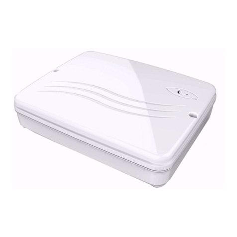
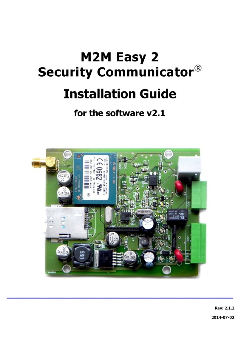
M2M RControl MQ03SD-RCALARM-RF User guide

M2M Services Ltd, 1 Kukush Str, building M8, Sofia 1309, Bulgaria, Web Site: www.m2mservices.com
M2M Services Ltd.
RControl Alarm
MQ03SD-RCALARM-RF
Installer’s Manual V 1.6
M2M Services Ltd, 1 Kukush Str, building M8, Sofia 1309, Bulgaria, Web Site: www.m2mservices.com

Content
Content .....................................................................................................................................................2
General Specifications.............................................................................................................................3
Wiring the RControl Alarm panel...........................................................................................................3
Wiring the power supply module.......................................................................................................3
Wiring a siren.......................................................................................................................................3
SMARTEnroll –self-learning zones........................................................................................................ 3
Wireless keyfobs......................................................................................................................................4
Supported functions............................................................................................................................4
Pairing a wireless keyfob....................................................................................................................4
Assigning a keyfob to different partition...........................................................................................4
Disabling a wireless keyfob ................................................................................................................5
Deleting all wireless keyfobs ..............................................................................................................5
Labelling the keyfobs ..........................................................................................................................5
Wired and wireless detectors................................................................................................................. 5
Adding wired detectors....................................................................................................................... 5
Pairing a wireless detector .................................................................................................................5
Pairing wireless panic button.............................................................................................................6
Disabling a wireless sensor.................................................................................................................7
Deleting all keyfobs and wireless detectors...................................................................................... 7
Keypads.................................................................................................................................................... 7
RControl Mobile Application ..................................................................................................................7
Remote Arming/Disarming via the RControl Application ...............................................................8
Changing the default keypad user code.............................................................................................8
Configuring the RControl Alarm.............................................................................................................8
General settings of RControl Alarm ...................................................................................................8
Configuring the partition ....................................................................................................................8
Configuring the zones..........................................................................................................................9
Zone types ............................................................................................................................................ 9
Configuring the panic button of the keyfob.....................................................................................10
Using multiple keypads for different Partitions..............................................................................10

General Specifications
•Built-in GPRS communicator
•Remote control via Smartphone
•2 Partitions
•8 Wired zones
•32 Wireless zones
•Supports up to 16 keyfobs with rolling code
•1 bell output and 1 programmable output (open collector 500mA)
•Short circuit protection of the AUX
Wiring the RControl Alarm panel
Wiring the power supply module
•The L and N terminals should be connected to the powerline (220V)
•The -V output should be connected to the (-) of the alarm panel
•The +V output should be connected to the (+) of the alarm panel
Wiring a siren
The siren should be connected to AUX(+) and BELL(-). The programmable output for the siren BELL(-) is
an open collector 500mA.
SMARTEnroll –self-learning zones
RControl Alarm panel supports SMARTEnroll feature –preconfigured settings and self-learning zones,
which in most cases eliminate the need of initial programming of the alarm panel. This simplifies the
installation process in the most commonly used scenario, when only instant zones with no entry/exit
times are needed.
By default, all wired zones of the alarm panel are initially set to “SMART Enroll” type. When a new wired
detector is connected to any zone (when the zone is closed), the zone is registered automatically and
the panel starts monitoring that zone. Zones Z1-Z7 are self-registered as instant zones and zone Z8 –as a
tamper zone (24h Tamper). When a new zone is being self-registered, the panel reports an event
“Added module, Zone N” with ContactID E-531.
By default, when a zone is not used it should not be short circuited to the AUX(-). However, if a zone is
already self-registered and will be no longer used, it should be short circuited to the AUX(-) or it should
be disabled, as described in section “Configuring the zones of RControl Alarm panel”.
When you pair a wireless zone it also automatically registers as instant zone.
If the default configurations are not suitable, the zones can be configured from the RControl Admin
Portal, as described in the section “Configuring the zones of RControl Alarm panel”.

Wireless keyfobs
Supported functions
The wireless keyfobs have 4 buttons - Full Arm, Home Arm, Disarm and Panic. By default, only the Full
Arm and Disarm buttons are active.
To enable the Home Arm button, you need to have at least one STAY zone. Please refer to the
“Configuring the zones” section.
To enable the Panic buttons of the keyfobs, please refer to the “Configuring the panic button” section.
Pairing a wireless keyfob
The RControl Alarm panel supports up to 16 wireless keyfobs. 2 keyfobs are included in the standard kit
and they are already paired.
To use additional keyfobs you should first pair them with the alarm panel.
Note: To be able to enter into learning mode, make sure that the panel is DISARMED!
To enter into learning mode, press the white button of the RF receiver of the panel. The red LED
indicator of the RF receiver will turn ON. After this LED indication, press any button of the wireless
keyfob (hold the button at least 1 sec). The siren will beep once, which indicates that the keyfob was
paired and the procedure was successfully completed.
Note: It’s recommended to pair the keyfob with Disarm button. That way you will not arm the panel by
mistake which will not allow you to pair the next keyfobs before you disarm the panel.
The learning mode lasts 10 seconds. If the receiver does not receive signal from the keyfob in the
timeframe of 10 seconds, the pairing procedure will be terminated. The siren will beep 4 times to
indicate an error.
When a new keyfob is paired, the panel reports an event “Access Granted, User N” with ContactID E-
422. Each keyfob reports with different user number.
You need to repeat the pairing procedure for each additional keyfob.
Note: To allow the panic button on the keyfob please refer to section “Configuring the panic button”
Assigning a keyfob to different partition
By default the keyfob controls the first partition after the pairing procedure. If there is a more than one
partition set you can set the keyfob to control a particular partition. To do that log in the RControl
Admin Portal, navigate to RControl Alarm menu, section Keyfobs and choose the desired Partition for
each keyfob.
Note: By default, each keyfob controls only one partition. If you want to control both partitions with a
single keyfob, choose Partition=All for that particular keyfob in the RControl Admin portal. The buttons
of the keyfob from the upper row will control Partition 1, the buttons from the lower row will control
Partition 2. You will not be able to use Home Arm and Panic features of that keyfob.

Disabling a wireless keyfob
If a paired keyfob is lost, you can disable it from the RControl Admin Portal. To do that you have to
navigate to RControl Alarm menu, section Keyfobs and set “Enable” property to NO for the keyfob that
you want to disable.
Deleting all wireless keyfobs
To delete all the paired keyfobs, hold the white button of the RF receiver for around 10 seconds. After
the LED indicator goes OFF and you hear a one-time confirmation sound from the siren, ALL the paired
keyfobs will be deleted from the receiver memory.
NOTE: This procedure will delete all paired keyfobs! To pair them again, you should repeat the pairing
procedure for each keyfob.
Labelling the keyfobs
Each keyfob reports with different user number in the range between 101-116. When pairing the
keyfobs they automatically receive labels “Keyfob 101 –Keyfob 116”. These labels appears in the
mobile application when arming/disarming with keyfob.
You can change the keyfob labelling anytime from the RControl Admin Portal by navigating to RControl
Alarm menu, section Keyfobs. The End User can also change the labeling from the mobile application by
navigating to Settings menu, section Labels if the End User is a Master User.
Wired and wireless detectors
Adding wired detectors
Detectors with normally closed relay contacts are used. The zones of the alarm panel are digital inputs
thus no EOL (end-of-line) resistors should be used. The detectors should be connected to the AUX(-) and
to a zone of the alarm panel. The tamper can be connected to a zone configured as 24h tamper.
Pairing a wireless detector
The RControl Alarm panel supports up to 32 wireless detectors.
NOTE: You cannot pair detectors while the system is armed. Before entering into learning mode first
make sure that the panel is DISARMED!

To enter into learning mode for the wireless detectors, press the white button of the RF receiver of the
panel. The red LED indicator of the RF receiver will turn ON. After this LED indication, activate twice the
wireless detector.
The siren will beep one time if the detector was successfully paired. The siren will beep four times if
there was an error during the pairing.
When a new detector is successfully paired, the panel reports an event “Added module, User N” with
ContactID E-531.
You need to repeat the pairing procedure for each additional detector.
NOTE: If after pressing the white pairing button the RF receiver does not receive any signal from the
wireless keyfob/detector within 10 seconds, the pairing procedure will be automatically canceled. The
siren will beep 4 times to indicate an error.
1. Pairing an M2M wireless magnetic detector
To pair the M2M magnetic detector, enter in learning mode, then open and close the magnet
two times. Wait 1-2 seconds after each opening/closing.
Do not use the tamper button of the magnetic detector to pair it.
2. Pairing an M2M wireless PIR detector
To pair the M2M wireless PIR detector, you have to activate it twice. Note that the PIR detector
should be in TEST mode.
- Open the sensor and switch the MODE jumper from position USE to position TEST.
- Close the sensor and wait till it initializes –wait for the LED to stop blinking.
- Enter in learning mode (press the white button on the RF receiver)
- Activate the sensor twice by moving in front of the sensor –activate the sensor once and wait
till the led stops blinking, then activate it second time. The sensor LED should blink on each
activation!
- Don’t forget to return the MODE jumper to position USE. If the jumper remains on position
TEST this will reduce battery life.
Do not use the tamper button of the PIR detector to pair it.
3. Pairing DSC wireless PIR detector
To pair the DSC wireless PIR detector, enter in learning mode (press the white button on the RF
receiver) and then press twice the Tamper button at the back of DSC PIR detector. The DSC PIR
does not support “Test Mode” (the sensor can’t send two events in the timeframe of 10
seconds) so you can’t pair the detector by moving in front of it.
4. Pairing DSC wireless fire detector
To pair the DSC fire detector, enter in learning mode (press the white button on the RF
receiver). Then press the Test/Reset button of the wireless fire detector twice - after the first
press of the button the wireless fire detector will make a clicking noise for around 5 seconds.
After this indication press the button again to pair the sensor.
Pairing wireless panic button
M2M wireless magnetic sensor supports “Panic button” feature. The panic button of the magnetic
sensor must be paired to a separate zone from the zone of the magnetic contact itself. Follow the
standard pairing procedure by pressing the panic button twice.

Disabling a wireless sensor
You can disable single wireless sensor from the RControl Admin portal. Go to the RControl Alarm menu,
RF Zones tab, and choose Enabled=No for that particular sensor.
Deleting all keyfobs and wireless detectors
Press and hold the white button of the RF receiver 3 times for around 10 seconds, until the LED indicator
goes OFF each time. This will delete ALL the paired keyfobs and wireless detectors from the memory.
NOTE: This procedure will delete all paired keyfobs and wireless detectors! To pair the keyfobs
and the wireless detectors again, you should repeat the pairing procedure for each keyfob and
detector.
NOTE: Before you start the deleting procedure make sure the panel is DISARMED.
NOTE: All the other settings will not be deleted, e.g. Entry/Exit Delay time, Partition configurations etc. If
you want to change those setting you must log in the RControl Admin Portal.
Keypads
The RControl-RF-KB version of the alarm panel supports 1404RKZ and 1555RKZ DSC keypads.
The keypad should be powered from AUX(+) and AUX(-).
Connect terminal R (RED) of the keypad to AUX(+) of the alarm panel.
Connect terminal B (BLK) of the keypad to AUX(-) of the alarm panel.
Connect terminal G (GRN) of the keypad to terminal A of the alarm panel.
Connect terminal Y (YEL) of the keypad to terminal B of the alarm panel.
The default keypad user code of the alarm panels is “1234”.
The user code can be changed by the end user via the RControl mobile application (refer to section
RControl Mobile Application)
RControl Mobile Application
The RControl mobile application is available for Android, iOS and Windows Phones.
With the RControl mobile application the end user can:
✓Monitor the status of the alarm panel
✓View events log up to one year back in time
✓Remotely Arm/Disarm the alarm system
The application can be download by scanning the following QR codes:
Initial end user login credentials for the app are provided with the alarm panel.
At the first login, it is strongly recommended that the end user changes the User name and Password and
provides an email for password recovery.

Remote Arming/Disarming via the RControl Application
To enable the remote control via the mobile application, go to Menu > Settings > Remote Arming/Disarming
and enable the Arming/Disarming feature.
Ask the end user to enter a Remote PIN code of their choice and Disarm (or Arm) from a keyfob or the
keypad within 2 minutes to complete the initial pairing procedure.
Changing the default keypad user code
The end user can change his keypad user code from the mobile application.
To change the code go to Menu > Settings > Remote Arming/Disarming > Change Remote PIN.
Configuring the RControl Alarm
In general, the alarm panels are preconfigured with a template according to the needs of each customer.
If any changes to the basic configurations are needed you can apply them from the RControl Admin
Portal https://www.m2mservices.com/admin by logging with your administrative credentials.
You can find the alarm panel by its serial number or by account number, IMEI, etc.
Select the RControl Alarm System, press the right button and choose “RControl Alarm” menu.
General settings of RControl Alarm
•Account Number –in the field “Account No” you must fill the number with which the panel will
report to the central monitoring station. The Account No. must be 4-digits long. By default the alarm
panel is configured to report with Account No. “0000”
•Periodical tests interval –in this field you can configure the interval for the periodical test messages
(in seconds), that the alarm panel will send.
•NOTE: This interval is different from the interval configured for the supervision of the GPRS
connection –the “heartbeat interval”. The connection is supervised on every 10 minutes by default
whereas the periodical tests are usually sent every couple of hours (e.g. 12 or 24 hours).
•Configuring a delay in case of mains power outage –in the field “Delay”, section “Main Power” you
can configure the delay (in seconds) after which the device will report the mains power outage.
•Configuring the Battery level thresholds - In section ”Battery”, field “Battery low” you can set a low
voltage threshold, under which the alarm panel will send “Low Battery” event. In the filed “Battery
Critical Low” you can set even lower voltage threshold and if the battery voltage goes under this
level, it will be considered as critically low.
In order to preserve the battery from permanent damage, you can configure the panel to shut down
automatically if the voltage of the battery drops under the critically low threshold. You can enable that
feature by checking the “Auto shutdown when battery critical low” checkbox.
Configuring the partition
The RControl RF Alarm panel supports 2 Partitions.
•You can configure different Partition settings from RControl Alarm menu, section “Partitions”:
•Partition name –the name which would be visible in the mobile application.
•Entry time (in seconds)

•Exit time (in seconds) –the time interval from the physical arming from a user and the arming of the
alarm panel. You can choose when the Exit time will be applied –when arming from a wireless
keyfob, in case of remote arming from the mobile application or both.
•Alarm cycle duration (in seconds) –the time interval when the siren will be active after an alarm
event
•Enable sound indication from the siren when the alarm panel is armed and disarmed
•Sound indication from the siren in case of tamper alarm
Configuring the zones
The RControl RF Alarm supports up to 8 wired and up to 32 wireless zones. If you need to change the
default self-learning behavior, you can configure the zones from the “RControl Alarm” menu, section
“Zones” for the wired zones or “RF Zones” for the wireless zones.
With a double click on the selected zone you can:
•Change the name of the zone –from section “Zone name”
•Enable or Disable the zone –from section “Enabled”
•Set the type of the zone –Instant, Entry/Exit, Follow, Tamper, Panic, Fire and etc. –from the menu
“Zone type”. Select “Disabled” if the zone will not be used
•If you have configured a zone as a “Keyswitch zone” you can choose if the alarm panel would be
Armed/Disarmed when this zone is activated. This can be configured from the menu “Keyswitch
action”
•Configure zone arming type = “Full arm” and “Stay arm” – from menu “Keyswitch arming”.
•Choose if the siren will be activated when the zone is violated –from section “Notification type”
•Can choose if every violation of the zone will be reported during the alarm cycle time. You can
configure this from section “Report All During Alarm Cycle”.
If this setting is disabled only the initial violation will be reported and all following activations will
not be reported until the alarm cycle time expires. When the alarm cycle time expires, the zone
restore event will be reported only when the zone is really restored. In addition, even when there
was a restore during the alarm cycle, this restore will not be reported until the expiration of the
alarm cycle time or until the partition is disarmed.
Zone types
•Smart Enroll –by default all zones are configured as “Smart Enroll”zones. This means that the
detectors added on these zones will be automatically registered (self-learned) as Instant zones. If
you want to configure different zone type you can do that from the RControl Admin portal > Device
Dashboard > RControl Alarm Settings.
•Entry/Exit zone –The Entry/Exit zones can be violated during the entry/exit time delay without
causing an alarm event.
If an Entry/Exit zone is violated while the system is armed, the alarm panel will start counting the
entry time. If the system is not disarmed during the entry time an alarm event is generated.
NOTE! If the entry/exit time is 0 sec, the Entry/Exit zone works as an Instant zone.
•Follow zone - This zone can be violated during the entry/exit delay time without generating an
alarm event. If the zone is violated while the panel is armed, the panel immediately generates an
alarm event (without counting entry time). It is called “Follow” zone because it depends on the
Entry/Exit zone. If the Follow zone is violated after an Entry/Exit zone has also been violated then
the alarm panel will wait until the entry time passes before generating an alarm event.

If the Follow zone was violated before any Entry/Exit zone was violated, then an alarm event will be
generated immediately.
NOTE! If the entry/exit time is 0sec, the Follow zone will work as an Instant zone.
•Instant zone - If this type of zone has been violated when the panel is armed, the panel will
immediately generate an alarm event. The arming of the alarm panel is not be possible if an Instant
zone is violated. In this case the alarm panel sends a ContactID event E-374 (Exit Error, in Zone N),
reporting the first of all the violated zones which prevent the panel from arming.
•Follow STAY zone - This is a Follow zone that is not monitored when the panel is partially armed
(STAY Arm)
•Instant STAY zone - This is an Instant zone that is not monitored when the panel is partially armed
(STAY Arm)
Configuring the panic button of the keyfob
Besides the option of configuring a 24h Panic zone of the panel, you can also use the built-in panic
button of the wireless keyfob. For firmware versions higher than 6.5.22 it is disabled by default. You
can enable the panic button of the keyfob from the RControl Admin Portal, Device Dashboard ->
RControl Alarm Settings, “Peripherals” section.
Using multiple keypads for different Partitions
If you have 2 Partitions you can assign a second keypad to the second Partition. You cannot control 2
Partitions from one keypad.
In order the system to differentiate the two keypads, each keypad must have unique address. By
default, all keypads come with address 1, so you will need to change the address of the second keypad.
To assign address 2 to the second keypad follow the steps below:
Press the white button of the RF receiver to enter in learn mode.
Press *22 on the keypad to assign the keypad to address 2.
Once you have different addresses to each keypad you need to assign them to a Partition from the
RControl Admin Portal > Device Dashboard > RControl Alarm Settings > Modules > Add Keypad.
Table of contents
Other M2M Security System manuals
Popular Security System manuals by other brands

Diamond
Diamond Ronin Sentinel user manual

3xLogic
3xLogic V250 Hybrid quick start guide

National Security Systems
National Security Systems Security System user guide

Rosslare
Rosslare HLX-40 Installation and programming manual

Hella
Hella KL Junior plus Mounting instructions

NAPCO
NAPCO MAGNUM ALERT 825 SYSTEM manual