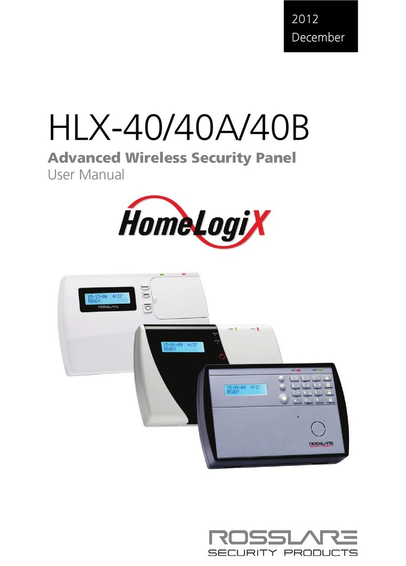
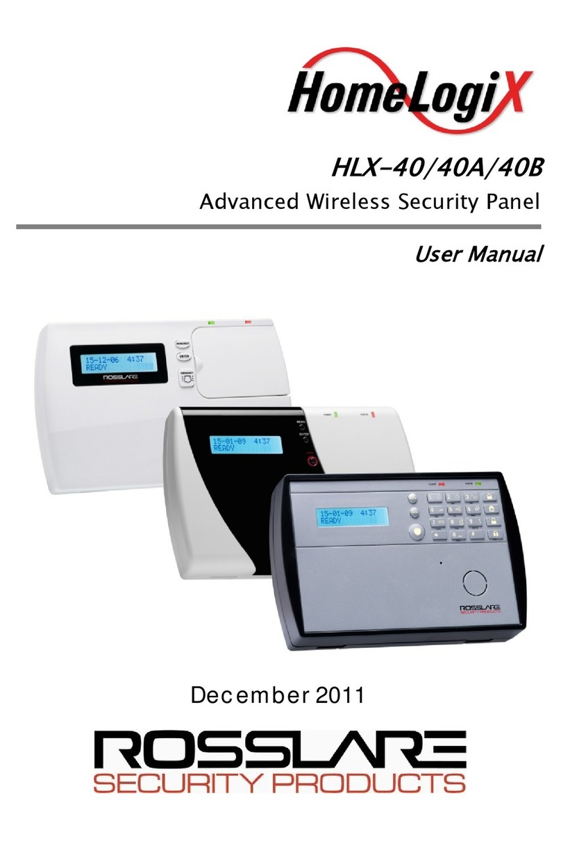
Rosslare HLX-40 Assembly instructions

2013
May
HLX-40/40A/40B
Advanced Wireless Security Panel
Hardware Installation and Programming Manual

Copyright © 2013 by Rosslare. All rights reserved.
This manual and the information contained herein are proprietary to REL, RSP Inc. and/or
their related companies and/or subsidiaries’ (hereafter:”ROSSLARE”). Only ROSSLARE
and its customers have the right to use the information.
No part of this manual may be re-produced or transmitted in any form or by any means,
electronic or mechanical, for any purpose, without the express written permission of
ROSSLARE.
ROSSLARE owns patents and patent applications, trademarks, copyrights, or other
intellectual property rights covering the subject matter in this manual.
TEXTS, IMAGES, AND ILLUSTRATIONS INCLUDING THEIR ARRANGEMENT IN THIS
DOCUMENT ARE SUBJECT TO THE PROTECTION OF COPYRIGHT LAWS AND OTHER
LEGAL RIGHTS WORLDWIDE. THEIR USE, REPRODUCTION, AND TRANSMITTAL TO THIRD
PARTIES WITHOUT EXPRESS WRITTEN PERMISSION MAY RESULT IN LEGAL
PROCEEDINGS.
The furnishing of this manual to any party does not give that party or any third party any
license to these patents, trademarks, copyrights or other intellectual property rights,
except as expressly provided in any written agreement of ROSSLARE.
ROSSLARE reserves the right to revise and change this document at any time, without
being obliged to announce such revisions or changes beforehand or after the fact.

Table of Contents
HLX-40 Hardware Installation and Programming Manual iii
Table of Contents
1. Introduction..................................................................... 10
1.1 General ............................................................................................ 10
1.2 Special Features ................................................................................ 11
2. HLX-40 Quick Reference.................................................. 12
2.1 The Panel.......................................................................................... 12
2.2 The Keypad ...................................................................................... 13
2.2.1 Keypad Operated Functions ....................................................................... 14
2.3 Sound Indicators............................................................................... 15
2.4 LED Indicators................................................................................... 15
3. Specifications .................................................................. 16
3.1 RF Data............................................................................................. 16
3.2 Environmental Data .......................................................................... 16
3.3 Electrical Data................................................................................... 17
3.4 Communication................................................................................ 18
4. Installation ...................................................................... 19
4.1 Unpacking the Equipment................................................................. 19
4.1.1 HLX-40 Package Content........................................................................... 19
4.2 Supply Power to the Unit .................................................................. 19
4.3 Planning & Programming .................................................................. 19
4.4 Wiring the System ............................................................................ 19
4.4.1 Wiring the HLX-40..................................................................................... 20
4.4.2 Resistors.................................................................................................... 21
4.4.3 Siren Relay Output – Wiring to External Siren.............................................. 22
4.4.4 Wiring Auxiliary Outputs 1 and 2 ............................................................... 22
4.4.5 Wiring the Zone 40 Wired Input................................................................. 23
4.4.6 Wiring the Wired Tamper Input.................................................................. 23
4.4.7 Wiring the HLX-40 Telephone Connectors.................................................. 23
4.5 Connecting the MD-CC101 GSM Stick.............................................. 23

Table of Contents
iv HLX-40 Hardware Installation and Programming Manual
4.6 Connect the AC Transformer ............................................................ 24
4.7 Connecting to a PC .......................................................................... 25
4.8 Mounting the Back Plate................................................................... 25
4.8.1 General..................................................................................................... 25
4.8.2 Required Space ......................................................................................... 26
4.9 Dismounting the Control Panel ......................................................... 26
4.10 Replacing the Backup Battery............................................................ 26
5. Programming the HLX-40 ............................................... 28
5.1 Overview .......................................................................................... 28
5.2 Enrolling Wireless Devices and Remote Controls................................ 28
6. Installer Menu ................................................................. 29
6.1 Change Code ................................................................................... 30
6.2 Zones ............................................................................................... 30
6.3 Enrolling........................................................................................... 32
6.3.1 Detectors .................................................................................................. 33
6.3.2 Remote Controls (KE-30 RFID Function) ...................................................... 33
6.3.3 RF Siren..................................................................................................... 34
6.3.4 Keypads.................................................................................................... 35
6.3.5 Repeaters.................................................................................................. 35
6.4 Security ............................................................................................ 35
6.4.1 Exit Delay .................................................................................................. 36
6.4.2 Exit Restart................................................................................................ 37
6.4.3 Entry Delay................................................................................................ 37
6.4.4 Auto Arming ............................................................................................. 38
6.4.5 Siren Time................................................................................................. 38
6.4.6 Siren Mode ............................................................................................... 38
6.4.7 Relay Polarity............................................................................................. 38
6.4.8 Local Siren ................................................................................................ 39
6.4.9 Wired Siren ............................................................................................... 39
6.4.10 Supervision Time ....................................................................................... 39
6.4.11 Jamming ................................................................................................... 39
6.4.12 No Activity Time ........................................................................................ 39
6.4.13 Trouble Beeps ........................................................................................... 40

Table of Contents
HLX-40 Hardware Installation and Programming Manual v
6.4.14 Bypass Option ........................................................................................... 40
6.4.15 Quick Arm ................................................................................................ 41
6.4.16 Arm Instant ............................................................................................... 41
6.4.17 Panic Button.............................................................................................. 41
6.4.18 Duress Code.............................................................................................. 42
6.4.19 Alarm Cancel ............................................................................................ 42
6.4.20 Alarm Abort Time...................................................................................... 42
6.4.21 Backlight Time........................................................................................... 43
6.4.22 Hide Display .............................................................................................. 43
6.4.23 Key Beeps ................................................................................................. 43
6.4.24 Select Language ........................................................................................ 43
6.4.25 EN-CENELEC ............................................................................................. 44
6.4.26 CP-01 ....................................................................................................... 45
6.5 Communications .............................................................................. 47
6.5.1 System Telephone ..................................................................................... 47
6.5.2 GPRS Setup ............................................................................................... 47
6.5.3 Private Report............................................................................................ 48
6.5.4 CS Report Setup........................................................................................ 49
6.5.5 Line Test ................................................................................................... 51
6.5.6 AC Fail Report ........................................................................................... 51
6.5.7 Fax Defeat................................................................................................. 52
6.5.8 2-Way Voice Behavior................................................................................ 52
6.5.9 Number of Rings ....................................................................................... 52
6.5.10 Select Region/Country ............................................................................... 53
6.6 Automation ...................................................................................... 53
6.6.1 Keypad Manual ......................................................................................... 53
6.6.2 Set Triggers............................................................................................... 53
6.7 Messages.......................................................................................... 54
6.7.1 Keypad Mute ............................................................................................ 55
6.7.2 Voice Mute ............................................................................................... 55
6.7.3 House Name ............................................................................................. 55
6.7.4 Custom Zones ........................................................................................... 55
6.8 Maintenance .................................................................................... 56
6.8.1 Factory Defaults......................................................................................... 56
6.8.2 RF Test ...................................................................................................... 57
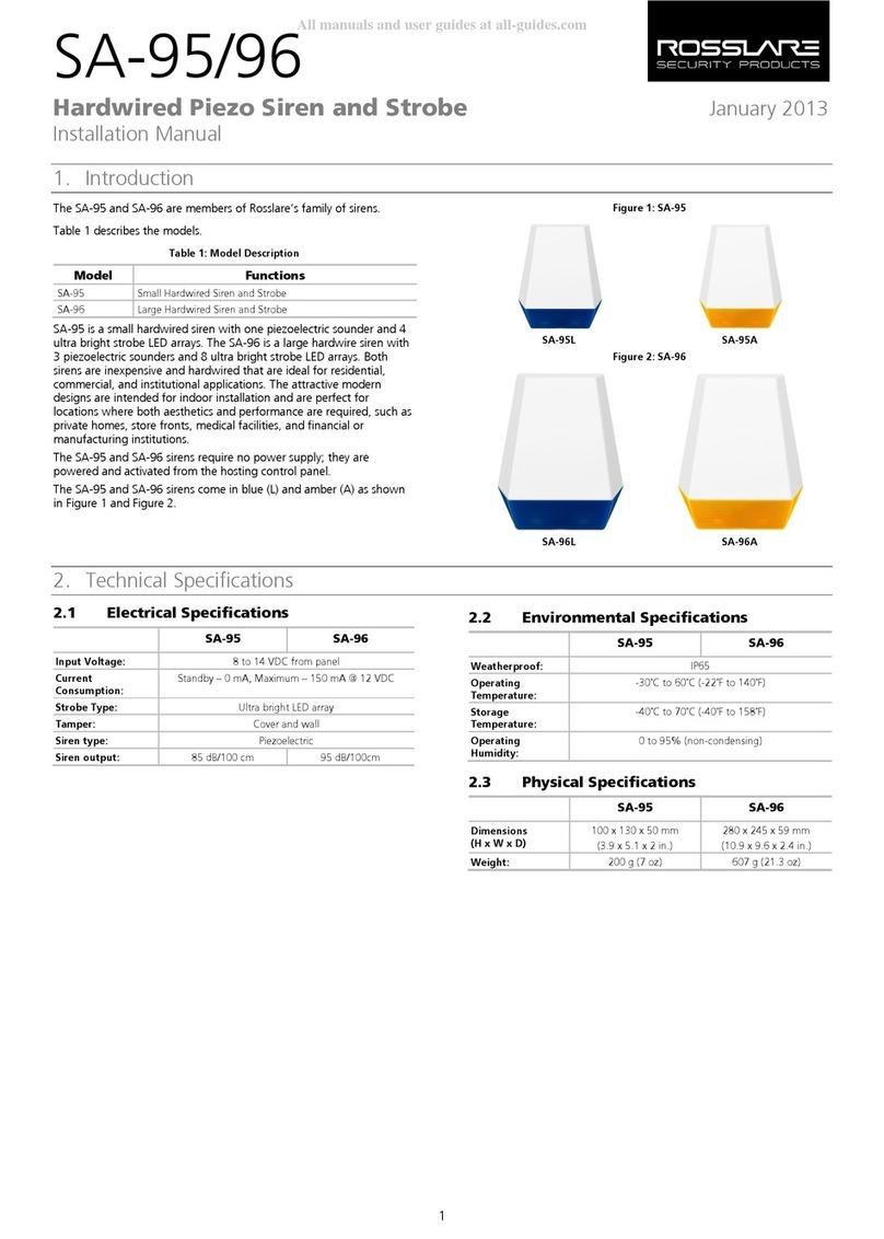
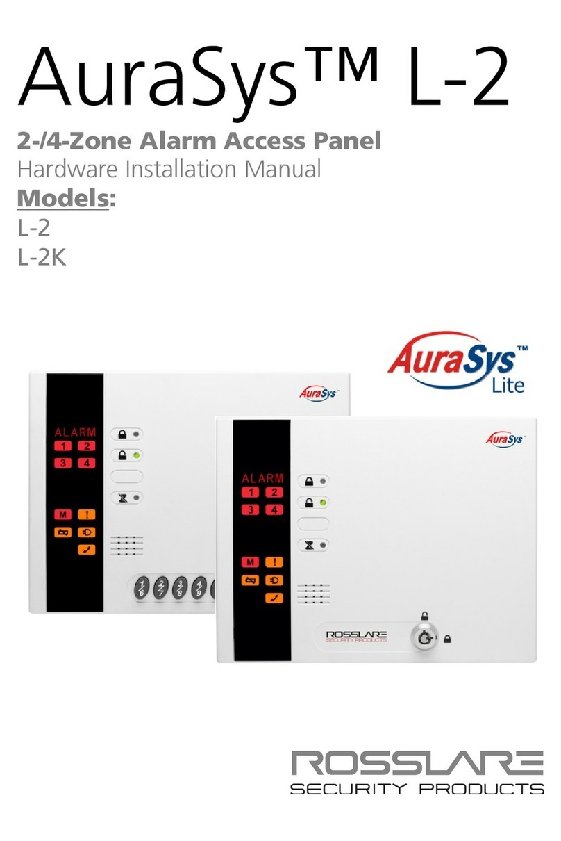
Table of Contents
vi HLX-40 Hardware Installation and Programming Manual
6.8.3 Test Indicators ........................................................................................... 57
6.8.4 Sirens Test................................................................................................. 58
6.8.5 Test Devices .............................................................................................. 58
7. User Menu Structure....................................................... 59
8. Reading the Event Log ................................................... 61
A. Quick Reference to Installer Menu................................ 62
B. Quick Reference to User Menu ...................................... 64
C. Sensor Placement and Helpful Reference Tables ........ 65
C.1 Default Zone Descriptions ................................................................. 65
C.2 Custom Zone Descriptions ................................................................ 66
C.3 Detector Deployment Plan ................................................................ 66
C.4 Remote Control ................................................................................ 68
D. Reporting Codes.............................................................. 69
E. GSM Stick Errors.............................................................. 71
F. Settings Requirements for CENELEC............................. 72
G. Default Parameter Values.............................................. 73
H. Labeling Instructions ...................................................... 78
I. Declaration of Conformity............................................. 79
J. Limited Warranty ............................................................ 80

List of Figures
HLX-40 Hardware Installation and Programming Manual vii
List of Figures
Figure 1: HLX-40 .......................................................................................... 10
Figure 2: HLX-40A........................................................................................ 11
Figure 3: HLX-40B ........................................................................................ 11
Figure 4: HLX-40 Panel ................................................................................. 12
Figure 5: HLX-40 Keypad.............................................................................. 13
Figure 6: Panel Wiring .................................................................................. 20
Figure 7: Resistors ........................................................................................ 21
Figure 8: Wiring to External Siren ................................................................. 22
Figure 9: Wiring to Aux Outputs................................................................... 22
Figure 10: Wiring to Zone 40 Input............................................................... 23
Figure 11: Wiring to Tamper Input................................................................ 23
Figure 12: Wiring to Telephone .................................................................... 23
Figure 13: GSM Assembly............................................................................. 24
Figure 14: Back Plate Wiring......................................................................... 25
Figure 15: Back Plate Mounting Holes........................................................... 25
Figure 16: Mounting .................................................................................... 26
Figure 17: Backup Battery............................................................................. 27

List of Tables
viii HLX-40 Hardware Installation and Programming Manual
List of Tables
Table 1: Control Panel Functions .................................................................. 12
Table 2: Keypad Functions............................................................................ 13
Table 3: Keypad Operated Functions............................................................. 14
Table 4: Sound Indicators ............................................................................. 15
Table 5: LED Indicators ................................................................................. 15
Table 6: Resistor Color Scheme..................................................................... 21
Table 7: Resistors Provided ........................................................................... 21
Table 8: CP01 Menu..................................................................................... 45
Table 9: Trigger Type and Parameters ........................................................... 54
Table 10: User Menu Structure ..................................................................... 59
Table 11: Installer Menu ............................................................................... 62
Table 12: User Menu .................................................................................... 64
Table 13: List of CID Codes .......................................................................... 69
Table 14: GSM Stick Errors ........................................................................... 71

Notice and Disclaimer
HLX-40 Hardware Installation and Programming Manual ix
Notice and Disclaimer
This manual’s sole purpose is to assist installers and/or users in the safe and
efficient installation and usage of the system and/or product, and/or software
described herein.
BEFORE ATTEMPTING TO INSTALL AND/OR USE THE SYSTEM,THE INSTALLER AND
THE USER MUST READ THIS MANUAL AND BECOME FAMILIAR WITH ALL SAFETY
REQUIREMENTS AND OPERATING PROCEDURES.
The system must not be used for purposes other than those for which it
was designed.
The use of the software associated with the system and/or product, if
applicable, is subject to the terms of the license provided as part of the
purchase documents.
ROSSLARE exclusive warranty and liability is limited to the warranty and
liability statement provided in an appendix at the end of this document.
This manual describes the maximum configuration of the system with the
maximum number of functions, including future options. Therefore, not
all functions described in this manual may be available in the specific
system and/or product configuration you purchased.
Incorrect operation or installation, or failure of the user to effectively
maintain the system, relieves the manufacturer (and seller) from all or any
responsibility for consequent noncompliance, damage, or injury.
The text, images and graphics contained in the manual are for the
purpose of illustration and reference only.
All data contained herein is subject to change without prior notice.
In no event shall manufacturer be liable for any special, direct, indirect,
incidental, consequential, exemplary or punitive damages (including,
without limitation, any and all damages from business interruption, loss of
profits or revenue, cost of capital or loss of use of any property or capital
or injury).
All graphics in this manual are for reference only, some deviation between
the image(s) and the actual product may occur.
All wiring diagrams are intended for reference only, the photograph or
graphic of the PCB(s) are intended for clearer illustration and
understanding of the product and may differ from the actual PCB(s).

Introduction
10 HLX-40 Hardware Installation and Programming Manual
1. Introduction
1.1 General
The HLX-40 panel by Rosslare is the perfect wireless security system for
intrusion protection of the home, or small office providing security monitoring
and VIP Voice messaging.
Users receive the latest RF technology in a wide selection of advanced wireless
sensors and remotes, and benefit from smooth and easy operation of a large
number of security and communication options.
The HLX-40 panel is easy to install and set up via local programming and via
direct or modem connection to a PC running the HLX-40 PC Software.
The panel has two full split reporting features for communicating to central
station for Contact ID and 2-way voice enabled event reporting and vocal
communications.
VIP features include Voice Assist, where the panel uses voice to prompt the
user, Private Messaging to three destinations, with an optional 2-way voice
session for every message.
The HLX-40 comes in three attractive designs:
HLX-40
HLX-40A
HLX-40B
Figure 1: HLX-40

Introduction
HLX-40 Hardware Installation and Programming Manual 11
Figure 2: HLX-40A
Figure 3: HLX-40B
1.2 Special Features
40 zones – 39 wireless zones, 1 wired zone – and tamper
Supports 8 remote controls, 4 wireless sirens, 4 wireless keypads, and 4
repeaters
Programmable remote control buttons
Interactive telephone voice menu (voice interactive)
Flexible PGM automation features
Five custom textual and recordable zone descriptions
Advanced testing and diagnostics options
Remote (telephone) two-way voice and listen-in
Lockout feature upon wrong code entry
Programmable No Activity timer (Version 2.0 and up)

HLX-40 Quick Reference
12 HLX-40 Hardware Installation and Programming Manual
2. HLX-40 Quick Reference
This chapter describes the control panel and the keypad, as well as the chimes
emitted when the buttons on the keypad are pressed.
2.1 The Panel
Figure 4 presents the components of the wireless panel.
Figure 4: HLX-40 Panel
Table 1: Control Panel Functions
Menu Use to navigate between menus
Power Indicator Power LED: green
FLASHING when there is an AC power failure and during
Walk Test
Status Indicator Status LED: green On: system armed
Off: system disarmed
Flash: entry and exit delay (according to beep rate)
FLASHING without beeps during Walk Test
Keypad Door Open to access the keypad buttons
Local Sounder System speaker
Microphone Enables the recording of voice messages
Local Emergency Button Keep pressed for 3 seconds to sound a standard panic
alarm
Display LCD display
Enter Accept an entry or selection
Display Enter
Menu
Local Emergency
Button
Microphone
Local Sounder
Power Indicator
Status Indicator
Keypad Door
(HLX-40 and
HLX-40A)

HLX-40 Quick Reference
HLX-40 Hardware Installation and Programming Manual 13
2.2 The Keypad
Figure 5: HLX-40 Keypad
Table 2 describes the keypad functions:
Table 2: Keypad Functions
Key Icon Press to
Menu
Navigate between User and Installer
menus, and Normal mode
Navigate to the next menu or the next
option within a menu
Enter
Accept an entry or selection
Local Emergency
When pressed for 3 seconds a standard
panic alarm sounds
Keys 0 – 9 Enter alphanumeric entries
Press 0to enter a space
Away
Arm all sensors and detectors for use
when there is no one at home/office
Home
Arm all perimeter sensors and detectors as
defined by the installer (for use when
home/office is occupied)
Disarm
Disarm all armed sensors and detectors
Esc
Ignore an entry or move one level up in a
menu

HLX-40 Quick Reference
14 HLX-40 Hardware Installation and Programming Manual
2.2.1 Keypad Operated Functions
When the system is idle, the alphanumeric keys initiate the commands shown
in Table 3.
Table 3: Keypad Operated Functions
Press To
0 Memory Display
Press once to display the alarms caused during the last arming period per
zone. The first line of the displays shows the alarm memory, and the second
line shows the zone description, event and time. The display toggles between
zone description and the date by pressing Enter.
Press Menu to display the next alarmed zone.
Press Esc to exit.
Note: When EN-CENELEC standard is enabled, only the master user
can access the memory display.
1 PGM ON
Press once to enter PGM activation mode, the PGM status is indicated on the
right. Press 1 to activate PGM 1 and/or 2 to activate PGM 2.
2 PGM OFF
Press once to enter PGM deactivation mode, the PGM status is indicated on
the right. Press 1 to deactivate PGM 1 and/or 2 to deactivate PGM 2.
3 Chime ON/OFF
Manually toggle the chime on and off
4 Volume
Manually toggle the beep volume level
5 Sound ON/OFF
Manually toggle voice messages, keypad tone, and other sounds on and off
6 Bypass
Enter the User menu Bypass option
7 Record User Message
Record a voice message of up to 15 seconds. Press and hold key 7 for 3
seconds to erase a message.
8 Event Log Display
Press once to display the event log. The first line of the display shows the
event log and the second line shows the zone description (or system, if a
system event is displayed), event date and time. The display toggles between
zone description and the date by pressing Enter.
Press again or press Menu to display the next event.
Press Esc to exit the menu.
Note that a master code is required to access this function.
9 Play User Message
Listen to voice messages

HLX-40 Quick Reference
HLX-40 Hardware Installation and Programming Manual 15
2.3 Sound Indicators
Table 4 presents the sounds emitted by the system and push buttons if
enabled during programming.
Table 4: Sound Indicators
Sound Sounded when
Single beep A key is pressed
Long Beep There is an illegal key entry
Three short beeps An entry is successfully accepted.
Four short beeps a
minute
If enabled, on trouble condition.
Short beep every
second
An exit/entry delay is activated (beep sounded every 0.5
seconds during last 10 seconds of delay)
Chime 1 & 2 Two (2) various chime sounds, when feature is activated
Chime 3 Vocal announcement of “Zone Name” + Open
Aside from the indication sounds, the system also has a voice confirmation of
various events.
This table does not include actual alarm sounds.
Note that the audible indication of a fire zone differs from that of a normal
intrusion zone.
2.4 LED Indicators
Table 5 describes the LED indicators of the power and status indicators
Table 5: LED Indicators
Power LED
(Red)
Status LED
(Green)
Behavior
ON OFF Panel disarm
ON ON Panel Arm
ON FLASHES every 1 second
Exit/Entry mode when AC is ON
ON FLASHES every 0.5
seconds
Last 10 seconds of Exit/Entry
mode
Exit/Entry mode when AC is ON
FLASHES every 1 second FLASHES every 1 second Walk Test mode
FLASHES every 0.5
seconds
OFF AC Failure

Specifications
16 HLX-40 Hardware Installation and Programming Manual
3. Specifications
This chapter provides the various specifications in regard to all three HLX-40
control panels.
3.1 RF Data
RF Unit Type Integrated RF transceiver (two-way) shielded super heterodyne,
fixed frequency
Antenna Type Printed PCB type antenna
Operating
Frequencies
G series – 433.92 MHz
H series – 868.35 MHz
Receiver
Sensitivity
Up to -68 dBm (without GSM Stick)
Transmitter
Power
Up to +10 dBm, less based on country requirements
Range
(open field)
Up to 250 m in open space for detectors, and 110 m for hand-
held remote controls (without GSM Stick)
RF Device ID
Coding
Three-bytes non-replicated per sensor type, or multiples of 16
million possible codes, make it almost impossible to have two like
coded transmitters
The HLX-40 system has optimum range if installed according to the
manufacturer’s recommendations, though this range may be affected by radio
noise from high-power nearby sources, or interference with the signal
(blocking) by large metal surfaces, or multiple concrete walls.
3.2 Environmental Data
HLX-40 HLX-40A HLX-40B
Operation
Temperature
Range
0ºC to 60ºC (32ºF to 140ºF)
Storage
Temperature
Range
-25ºC to 70ºC (-13ºF to 158ºF)
Relative
Humidity 85% at 30ºC (non-condensing)
Dimensions
(L x W x D)
217 x 144 x 48 mm
(8.5 x 5.7 x 1.9 in.)
217 x 144 x 50 mm
(8.5 x 5.7 x 2.0 in.)
217 x 144 x 48 mm
(8.5 x 5.7 x 1.9 in.)
Weight 520 g
(1.1 lb)
548 g
(1.2 lb)
530 g
(1.2 lb)

Specifications
HLX-40 Hardware Installation and Programming Manual 17
3.3 Electrical Data
Two lines of 16 characters, backlit LCD display
Two fully programmable PGM open collector outputs, 200 mA, PTC
protected
External hardwired siren output
Case tamper protection
On-board, supervised wired zone and wired tamper inputs
Local, 80 dBA siren
220 VAC/50 Hz, 110 VAC/60 Hz (15 VDC, 800 mA) external power supply
Complies with the following standards:
CE, FCC, EN 50131-3, EN 50131-6, EN 50130-5, EN 50130-4, EN
60950-1, EN 50131-5-3, Security Grade 2, Environmental II
Current consumption:
without GSM: 90 mA (standby) 500 mA (max)
with GSM: 120 mA (standby) 1000 mA (max)
Auxiliary power output: 13.8 VDC, 500 mA max
Output voltage range max. 13.8 VDC, minimum 9 VDC
Maximum output pick-to-pick ripple 0.6 Vptp
Maximum auxiliary current output 200 mA – EN50131-6 standard
Battery
Internal backup battery: 800 mAh for 6 hours standby – not
EN50131-6 standard
Internal backup battery: 2000 mAh for 14 hours standby
Low battery detection under 10 V
Maximum battery (2000 mAh) recharge time 72 hours
Zone Input Specifications
Maximum loop current (shorted loop): 0.33 mA
Maximum loop voltage (open loop): 3.3 VDC
Loop shorted: 0 V – 0.5 V (0 to 1000K total loop resistance)
Loop normal: 1 V – 2.2 V (4340 to 16150K)
Loop open: 2.8 V – 3.3 V (31250K to infinite)

Specifications
18 HLX-40 Hardware Installation and Programming Manual
3.4 Communication
Frequencies: 433.92 MHz (G) and 868.35 MHz (H)
RF jamming detection (UL/EN selectable)
Proprietary anti-collision RF protocol
Programmable no-activity timer 1–30 minutes, per zone
Two central station numbers and accounts, backup and secondary modes
Reporting protocols: Contact ID
Three private telephone numbers for voice reporting, and two way voice
communications
Local connection (with MD-62) port for local upload/download, and
remote programming by PC software
Built-in telephone dialer and 2400 Baud rate modem

Installation
HLX-40 Hardware Installation and Programming Manual 19
4. Installation
4.1 Unpacking the Equipment
The contents of your package are listed below. First, make sure that all the
items in the kit have been included. If you find that any item is missing, contact
your dealer immediately.
4.1.1 HLX-40 Package Content
HLX-40/40A/40B unit
Wall Adaptor
Telephone cable
Installation screw set
4.2 Supply Power to the Unit
It is easier to enroll the ID codes of the transmitting devices to the system
before installation. Power the HLX-40 system using the external power
transformer or from the backup battery.
Please note that in order to initiate battery power, connect the battery, connect
external power (transformer), and then disconnect the power to initiate battery
power operation.
4.3 Planning & Programming
Register the location of each detector in the tables provided in Appendix C and
D. Mark the transmitters and detectors accordingly.
To program the system, refer to Chapter 5.
To mount the HLX-40 unit, refer to Section 4.8.
4.4 Wiring the System
The HLX-40 wiring plan is shown in Figure 6.
Release the screw on each terminal block and connect accordingly.

Installation
20 HLX-40 Hardware Installation and Programming Manual
4.4.1 Wiring the HLX-40
Figure 6: Panel Wiring
Input Description
Siren Relay output for external siren or strobe. Normally open
or normally closed for external siren contacts.
AUX 1 Programmable AUX outputs 1 and 2, 200 mA Sink
Current 12VDC open collector outputs Active Low.
AUX 2
GND Ground
ZONE Wired Zone (zone 40) Alarm input.
GND Ground
TAMPER Wired Zone (zone 40) Tamper input.
+15VDC VIN Input voltage from AC/DC adaptor VIN = 13.8–15
GND
+13.8VDC
(-) AUX (OUT)
Auxiliary Power output (to power external devices) +13.8
VDC 500 mA load current max. current limited.
LINE IN Telephone line in (from the wall to the system).
HOME TEL Telephone line out (from system to telephone device).
MD-62 Connection Socket
Connection socket for 10-pin plug connecting panel to
PC with MD-62.
+BAT- Battery connector
Wall Tamper Switch The tamper switch is pressed when the panel is mounted
on the wall.
Other manuals for HLX-40
6
This manual suits for next models
2
Table of contents
Other Rosslare Security System manuals

Rosslare
Rosslare HLX-40 User manual

Rosslare
Rosslare AYC-Q65 Assembly instructions

Rosslare
Rosslare HOME LOGIX HLX-24 Assembly instructions

Rosslare
Rosslare SA-95 User manual

Rosslare
Rosslare AuraSys L-2 Assembly instructions

Rosslare
Rosslare HLX-40 User manual

Rosslare
Rosslare HLX-40 User manual

Rosslare
Rosslare HLX-40 User manual

Rosslare
Rosslare AuraSys L-4 User manual

Rosslare
Rosslare HLX-40 User manual