M7 SPEED 60-4M7601 User manual

Rev 02-21-2018 Page 1 of 6
www.m7speed.com
Ultimate MINI Performance
M7 Speed
149 Byers Creek Rd., Unit 103
Mooresville, NC 28117
888-438-5767
R60 Carbon Fiber & Tegris Splitter
(Model years 2011-2016)
PN 60-4M7601
Installation Guide
M7 Speed engineers and manufactures the highest quality and best fitting Mini Cooper
accessories and performance parts available anywhere on Planet Earth! Please inspect
your parts when you receive them to verify everything is included and no damage has
happened during shipment. Read these instructions completely BEFORE attempting to
install this product. If you are not confident you can do the work described or do not
have the tools or skills necessary please contact a local M7 dealer (listed on or website
www.m7tuning.com) or a local automotive accessory installation center to perform this
work. We acknowledge not everything is perfect but we work very hard every day to
improve our products and make installations easier. If you have any comments please
contact M7 Customer Service directly at 704-663-0094. We encourage and welcome all
criticism Good or Bad. Thank you.
CONTENTS: Hardware Kit 90-1070
Qty
M7 P/N
Description
1
Splitter (Carbon Fiber or Tegris)
14
#12 Truss Head Self Tapping Screw (1 extra)
14
95-4001
Expanding Retainer-Black Plastic (1 extra)
1
95-9005
AVK Insert Tool #10-32
3
95-5002
#10-32 Expanding NutSert
2
95-9012
APR Strut Rod
4
95-3004-SS
#10-32 x 5/8" SHCS SS (Pre installed in strut rods)
6
95-7001-SS
#10 x 3/4" OD Flat fender washer
2
95-8019
#10-32 Half Height Nyloc Nut
TOOLS NEEDED:
•#2 Phillips screw driver
(power nut driver
recommended)
•Electric drill
•1/8” drill bit
•¼” drill bit
•3/8” drill bit
•3/8” open end wrench
•Plastic body clip removal tool
•7mm open end wrench
•8mm open end wrench
•5/32” Allen wrench
•Red Loctite (Thread locker)
•Tape measure
•Masking tape
•Silver Sharpie
•A friend to help

Rev 02-21-2018 Page 2 of 6
www.m7speed.com
Ultimate MINI Performance
M7 Speed
149 Byers Creek Rd., Unit 103
Mooresville, NC 28117
888-438-5767
CAUTION:
WHEN WORKING UNDER YOUR CAR ALWAYS USE THE RIGHT
EQUIPMENT FOR THE JOB. DON’T BE TEMPTED TO TAKE SHORT CUTS
OR USE INAPPROPRIATE SUPPORTS SUCH AS CONCRETE BLOCKS,
BRICKS OR WOOD. NEVER WORK UNDERNEATH A VEHICLE THAT IS
ONLY SUPPORTED BY A JACK. ONLY USE AXLE APPROVED STANDS OR
CAR RAMPS THAT ARE IN GOOD CONDITION AND PROPERLY RATED
FOR YOUR VEHICLE’S WEIGHT.
INSTALLATION:
1. Raise your car onto axle-stands or ramps that so you can easily work
under the front bumper of your vehicle.
2. Remove the plastic push rivet retainers and the two outer mud guard lips
from the bottom side of the factory bumper lip.
3. Clean the underside of the bumper to remove any loose dirt or damaged
hanging plastic bits caused by run-ins with parking lot curbs or ?. A
smooth surface is desired.
4. Place a piece of masking tape on your bumper nose at the point it wraps
and goes underneath and approximately on centerline. Determine the
centerline of the bumper by measuring the full width the grill opening and
dividing by 2. (Grill width/2) Mark this point on the masking tape.
5. Place a piece of masking tape in the approximate center on the splitter.
Draw a line at the centerline of the splitter using the center of the two
middle holes as the center of the splitter.
6. Place the splitter up to the bottom side of your bumper, aligning the back
edge of the splitter with the rear edge profile of the bumper lip and the
centerline marks on the bumper and splitter. Position the splitter so there
is no gap between the splitter and the back edge on the underside of your
bumper. (A friend is very helpful at this point) Verify the splitter is centered
and the overhang is equal left and right.
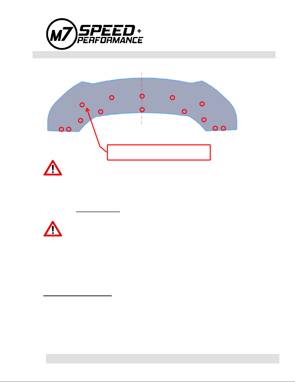
7. Using a ¼” drill bit or a Silver Sharpie® and the splitter as a template
guide, mark the bottom of your bumper cover at the fourteen (14)
locations indicated by the RED circles shown in Figure #1.
Check three (3) times that the marks and the splitter are aligned
correctly before drilling!

Rev 02-21-2018 Page 3 of 6
www.m7speed.com
Ultimate MINI Performance
M7 Speed
149 Byers Creek Rd., Unit 103
Mooresville, NC 28117
888-438-5767
Figure 1
CAUTION: STOP AS SOON AS THE DRILL BREAKS THROUGH.
THERE IS LIMITED CLEARANCE ABOVE THE BUMPER COVER.
8. Remove the splitter and set it to the side.
9. Pilot drill the fourteen (14) marked holes with a 1/8” drill first. Final drill the
holes to 3/8” diameter. Do not make the holes any larger than 3/8”. Clean
away any remaining burrs.
CAUTION: STOP AS SOON AS THE DRILL BREAKS THROUGH.
THERE IS LIMITED CLEARANCE ABOVE THE BUMPER COVER.
10.Insert the fourteen (14) plastic retainers into the 3/8” diameter holes. Push
the retainers into the holes until they snap in and are flush with the bottom
side of the bumper. It is a tight fit by design so some force will be
necessary. Do not make the holes any larger than 3/8”.
ATTACH THE SPLITTER:
11.Remove the masking tape from the splitter and bumper. Place the splitter
to the underside of you bumper. Align all the holes and thread in the
supplied Bright Zinc plated Truss Head screws through the splitter and
into the fourteen (14) plastic retaining clips.
12.Tighten all the fasteners once you are satisfied with the splitter position.
USE THESE 14 HOLES AS A GUILD TO
DRILL FOR RETAINER CLIPS

Rev 02-21-2018 Page 4 of 6
www.m7speed.com
Ultimate MINI Performance
M7 Speed
149 Byers Creek Rd., Unit 103
Mooresville, NC 28117
888-438-5767
CAUTION: DO NOT OVER TIGHTEN. USE A HAND SCREW DRIVER
TO FINAL TIGHTEN. REMEMBER-----YOUR ARE WORKING WITH PLASTIC
MATERIALS!
CAUTION: STRUT ROD INSTALLATION IS REQUIRED. THE
SPLITTER CREATES A LOT OF DOWNFORCE AND THE STRUT RODS ARE
REQUIRED TO STABILIZE AND ELIMINATE SPLITTER FLUTTER AT
SPEED. SPLITTER FLUTTER WILL SELF DISTRUCT YOUR SPLITTER AND
FRONT BUMPER. NOT INSTALLING THE STRUT ROADS WILL VOID ALL
WARRANTIES.
STRUT ROD INSTALLATION:
13.Loosely attach the strut rods to the splitter. Lengthen or shorten the strut
rods to a length that reaches the point where you want to attach them to
the bumper cover. Once you have located a suitable spot apply masking
tape in that general area and then mark the exact point where to drill.
General placement is approximately 1” either side of the lower grill, 4 ¾”
up from the splitter.
Figure 2
Approx. 1”
4 3/4”

Rev 02-21-2018 Page 5 of 6
www.m7speed.com
Ultimate MINI Performance
M7 Speed
149 Byers Creek Rd., Unit 103
Mooresville, NC 28117
888-438-5767
Before drilling any holes mock up the rod to make sure you have enough
available strut rod length. The strut rod uses left and right and threads so
turning the center shaft one direction lengthens the assembly and turning
it in the opposite direction shortens it. Verify the clevis is screwed into
each end of the rod equally and at least 1/2” is threaded inside the center
shaft so you have adjustment available when completed. Once everything
is as you want it final mark the LS and RS hole locations. Keep the RS
and LS hole locations symmetrical. REMEMBER…MEASURE THREE
TIMES…..DRILL ONCE
14.Using a ¼” drill bit, drill one single hole at each of the 2 spots you marked
on the bumper in the prior step. Do not make the holes any larger than
1/4”.
CAUTION: STOP AS SOON AS THE DRILL BREAKS THROUGH.
THERE IS LIMITED CLEARANCE BEHIND THE BUMPER COVER.
15.Install one metal expanding threaded insert into each of the ¼” holes flush
with the bumper cover. Follow the instructions included with the tool and
tighten to seat the insert in each LS & RS hole. DO NOT OVER TIGHTEN.
16.Disassemble the strut rods to remove the u-brackets from the rods. Bolt
one u-bracket to the splitter. On the splitter end of the strut rod sandwich
the splitter with one (1) flat washer on top and one (1) flat washer on the
bottom and then the supplied lock nut. Bolt one u-bracket to the bumper
cover. On the bumper end use one (1) stainless steel flat washer between
the strut rod u-bracket and the threaded insert you installed in the bumper.
Insert the strut rod to connect the two u-brackets aligning the u-brackets
so the M4 screws can be freely (no binding) installed through the center
rod. Once everything is aligned, again remove the center rod. Tighten the
screws holding the u-brackets to the bumper and splitter to 15 in-lbs.
(1.5Nm) MAX while maintaining the angular alignment of the u-brackets.
Install the center strut rod between the brackets, insert the M4 screws and
tighten.

Rev 02-21-2018 Page 6 of 6
www.m7speed.com
Ultimate MINI Performance
M7 Speed
149 Byers Creek Rd., Unit 103
Mooresville, NC 28117
888-438-5767
17. It is advised Blue Loctite be applied to the four 4mm screws on the
rotating joint nuts. If you Loctite any other nuts you will lose the ability to
adjust or remove the strut rods in the future. See Figure #3
Figure 3
18.Final align the splitter by shortening or lengthening the strut rods so that it
sits horizontal with the ground when your car is on a flat level surface and
no free play is noticeable. Once everything is aligned tighten the jam nuts
on the adjuster rods.
19.Final safety check all hardware for tightness and you are Done!
Enjoy the Ride and stay M7 Tuned………………….
Thank you
Team M7
Loctite these screws only
Table of contents
Other M7 SPEED Automobile Accessories manuals