M7 SPEED 70-530200 User manual

September 16, 2020 Page 1 of 12
Installation Guide
Gen 3 Countryman/Clubman Lift Kit
Part # 70-530200 (2.5” Lift)
M7 Speed engineers and manufactures the highest quality and best fitting MINI Cooper accessories and performance parts available
anywhere on Planet Earth! Please inspect your parts when you receive them to verify everything is included and no damage has
happened during shipment. Read these instructions completely BEFORE attempting to install this product. If you are not confident you
can do the work described or do not have the tools or skills necessary please contact a local M7 dealer (listed on our website
www.m7speed.com) or a local MINI repair shop or automotive accessory installation center to perform this work. We acknowledge not
everything is perfect but we work very hard every day to improve our products and make installations easier. If you have any
comments please contact M7 Customer Service directly at 704-663-0094. We encourage and welcome any and all criticism, comments
or product reviews. Thank you.
NOTE:
THE INSTALLATION OF THIS GEN 3 MINI COOPER LIFT KIT REQUIRES ADVANCED MECHANICAL SKILLS AND
TOOLS NOT TYPICALLY FOUND IN A D.I.Y. TOOL KIT. WE STRONGLY RECOMMEND THAT AN EXPERIENCED
MECHANIC OR INSTALLATION SHOP PERFORM THE INSTALLATION OF THIS KIT.
NOTE:
THIS GUIDE ONLY OUTLINES THE MAJOR STEPS REQUIRED TO PERFORM THE INSTALLATION. STANDARD
INDUSTRY PRACTICES AND GENERAL KNOWLEDGE OF VEHICLE ASSEMBLY AND DISASSEMBLY ARE NOT
DETAILED IN THIS GUIDE. THE INSTALLER ASSUMES ALL RESPONSIBILITY AND LIABILITY FOR ANY
DAMAGE ENCOUNTERED WHILE INSTALLING THESE PARTS. IN ADDITION THE INSTALLER ASSUMES ALL
RESPONSIBILITY AND LIABILITY FOR ANY DAMAGES OR INJURY THAT ARE A DIRECT OR INDIRECT RESULT
OF IMPROPER INSTALLATION AND/OR POOR WORKMANSHIP.

September 16, 2020 Page 2 of 12
CAUTION:
WHEN WORKING UNDER YOUR CAR ALWAYS USE THE RIGHT EQUIPMENT FOR THE JOB. DON’T BE TEMPTED
TO TAKE SHORT CUTS OR USE INAPPROPRIATE ITEMS. NEVER WORK UNDERNEATH A VEHICLE THAT IS
ONLY SUPPORTED BY A JACK. THIS MAY CAUSE SEVERE INJURY AND EVEN DEATH.
CAUTION:
SUPPORT YOUR CAR BY USING STABLE AND QUALITY AXLE STANDS THAT ARE IN GOOD CONDITION AND
PROPERLY RATED FOR YOUR VEHICLE’S WEIGHT. THIS INSTALLATION IS BEST ACCOMPLISHED USING AN
AUTOMOTIVE SERVICE LIFT.
KIT INCLUDES:
•2 x Front Riser Blocks + Hardware Kit
•2 x Rear Spring Riser Blocks + Hardware Kit
•2 x Rear Shock extensions + Hardware Kit
•2 x Front Sway Bar Links + Hardware Kit
•2 x Rear Sway Bar Links + Hardware Kit
Rear Suspension
DIS-ASSEMBLY:
1. Remove the plastic shields mounted to the bottom of the rear swing arms [8mm Socket]
2. Unsnap the wheel sensor and brake sensor wires from their retaining clips, located in each wheel well, so they
do not get damaged during the installation. This will give extra slack in the wires.
Figure 1: Rear Spring Riser Block-TOP
THESE TWO HOLES QRE REQUIRED TO FACE
TOWARDS THE FRONT OF THE CAR WHEN
THE RISER BLOCK IS CLAMPED TO THE
LOWER SWING ARM

September 16, 2020 Page 3 of 12
3. Remove the rear sway bar links completely from the rear suspension swing arm and the rear sway bar on both
sides of the vehicle. [E12 Socket, T30 socket, 14mm wrench]. These will not be reused.
4. Remove the rear shock lower bolts from both sides of the vehicle. [E20 Socket]
5. Remove the rear shock upper mount from the body by removing
the three M8 bolts. [E12 Socket]. Do not remove shocks from the
OE upper mount.
6. Remove the upper outer camber link bolt from the swing arm
assy. This provides extra droop travel helping with installing the
spring back into position in the next section.
7. Pull down on the swing arm and remove the rear coil springs.
Keep the rubber isolators for reinstallation.
a. NOTE: Before removing the rear coil springs mark them
for Right & Left, Top & Bottom locations.
RE-ASSEMBLY
INSTALL THE REAR SPRINGS
1. Place the rear spring riser blocks onto the rear swing arm with the
two isolator index holes facing forward. See Figure #1
2. From the bottom, feed the M7 supplied retaining bar through the
2” hole in the bottom of the swing arm. Insert the bolt and lock
washer through the retaining bar and into the riser block. Tighten
to 30 lb-ft [40 Nm]. Verify the two isolator index holes are facing
to the front of the car. See Figure #1 & #2
3. Place the lower spring rubber isolators onto the riser blocks indexing them
with the two locating holes.
4. Place the upper rubber spring isolators onto their location on the vehicle underbody.
5. If necessary use a coil spring compressor tool, compress the coil springs approximately 2” until they can be
reinstalled between the riser block on the swing arm and the body. Verify the spring orientation and the lower
spring pigtail is indexed correctly into the lower spring isolator before releasing tension. Release and remove the
coil spring compressor tools.
6. Reinstall the upper outer camber link bolt on the swing arm assy. Torque to 74 lb-ft [100Nm]
Figure 2: Rear Riser Block Assembly

September 16, 2020 Page 4 of 12
INSTALL THE REAR SHOCKS
FOR VDC Equipped Vehicles SEE Supplemental Information at the end
of this document
1. Bolt the M7 Speed upper rear shock extension block to the top of
the OE shock mount. Note the mount only fits flush one way. If
the extension block does not sit flush onto the OE mount, flip it
upside down so that it sits flush with no rocking. Bolt the extension
to the OE mount using the supplied M8 bolts and lock nuts. Torque
to 25 lb-ft [34 Nm].
2. Install the rear shocks onto the vehicle. Bolt the M7 extension
block, shock mount and shock assembly to the vehicle body using
the M7 supplied M8 bolts. Torque to 25 lb-ft [34 Nm]
NOTE: On VDC equipped vehicles use the OE bolts with the M7 supplied locknuts to bolt the M7 extension
to the shock top/VDC sensor and the M7 supplied bolts to bolt the M7 extension to the body.
3. Install the lower shock bolts on each side. Torque to 115 lb-ft [155 Nm].
Figure 3: Rear Shock Extension Block with VDC sensor.
Figure 4: Rear Shock Extension Block
with
VDC sensor.
Figure 4: Rear Shock Extension Block with VDC sensor. Installed in car.

September 16, 2020 Page 5 of 12
INSTALL THE M7 REAR SWAY BAR LINKS
1. Set both links to the same center to center length.
2. Lock the Jam Nut on the tie rod end.
3. Pre grease the bushings prior to installation through the Zerk fitting.
4. Insert the ball joint stud into the rear sway bar hole.
a. Place one thick washer on each stud.
b. Install the M10 castle nuts.
c. Torque to 30 lb-ft [40Nm]
d. Install the cotter pins.
5. Install the lower pivot point using the supplied M8 bolt and large
diameter washers and thread it into the lower swing arm in the OE
location.
6. Torque the lower pivot bolt to 25 lb-ft [34Nm].
7. Reinstall all the sensor wires into their mounting brackets.
8. Reinstall the plastic guards onto the bottom of the Rear Swing Arms.
NOTE:
When both sides of the rear suspension is completed safety check all components for
proper and complete installation and correct hardware tightness.
Figure 5: Rear Spring Spacer installed

September 16, 2020 Page 6 of 12
Front Suspension
The Front Strut Riser Block installs between the top of the factory OE strut mounting plate and the body mounting
location. It is designed to index with and fit flush on top of the OE plate. The Right and Left side use the same riser
block. The best way to install the riser block is to remove the entire strut, upright and hub from the vehicle as one
complete assembly. See Figure #6.
FOR VDC Equipped Vehicles SEE Supplemental Information at the end of this document
The following procedure addresses one side of the vehicle unless noted otherwise.
DIS-ASSEMBLY
UNDERHOOD
1. Remove the rear seal that runs
between the RH & LH strut towers.
Simply pull it up and off the
locating strip.
2. Remove the plastic tray located
between the seal (removed in step
1 above) and the windshield.
There are no clips or fasteners.
Simply pull it up and out of the
rear locating groove. Watch for
connected small hoses clipped to
the underside of this tray.
3. Remove the round black plastic
cap on top of each strut top.
4. Remove the chassis tie bar bolt on
top of each strut top. One per
side [15mm wrench]
5. Remove the plastic cover on top of each strut tower.
6. Remove three (3) of the five (5) strut top mounting bolts. Loosen the two (2) remaining bolts but keep the
threads fully engaged to hold the top of the strut from falling out. [13mm wrench]
UNDERCAR
1. Remove the underside protective cover [8mm socket - 14 screws]
2. Remove the OE sway bar link from the Front Sway Bar and the strut mounting tab. This will not be reused.
3. Remove the drive axle bolt from the center of the hub. [17mm Allen Hex Socket]
4. Remove the wheel speed sensor from the upright (hub carrier).
Figure 6: Underhood Seal

September 16, 2020 Page 7 of 12
5. Loosen the strut cartridge-to-upright clamp bolt and remove the bracket holding the brake lines and sensor
wires. Retighten the clamp bolt.
6. Unbolt the brake caliper assembly from the upright. Do not remove the caliper from the brake hose. Hang the
caliper assembly from the front of the car using wire or zip ties. Do not let it hang or place excessive stress on
the brake hose and sensor wires.
7. RIGHT SIDE ONLY: Remove the self-leveling headlight sensor arm bracket from the lower swing arm [10 mm
wrench] to prevent it from being damaged.
8. Remove the outer steering tie-rod nut and slide the steering tie rod pin out of the steering arm. It is a straight
pin and will disassemble without any force. [22mm hex wrench]
9. Remove the lower ball joint locking cross bolt & nut and slide the ball joint out of the upright. It is a straight pin
and will disassemble without any force. [16mm wrench & E14 socket]
10. Loosen and remove the center swing arm pivot bolt from the car. [E14 socket] See Figure #5
Figure 7: Center Pivot Bolt Right Side shown looking rearward

September 16, 2020 Page 8 of 12
REMOVE THE STRUT ASSEMBLY.
NOTE: THIS ASSEMBLY IS VERY HEAVY AND AWKWARD. At minimum, two (2) people are needed to remove and
reinstall the strut assembly.
Figure 8: Front Strut Assembly
11. With one person holding the strut assembly the second person removes the two (2) remaining bolts on top of
the strut tower. Remove the OE Strut assembly from the vehicle. Retain all the OE hardware for re-installation.
12. Clean the top of the OE plate if necessary.
13. Install the M7 Speed Riser Block on top of the OE plate and rotate it until it indexes and sits flush. Bolt the M7
Riser Block to the top of the OE Strut top using
the factory OE M8-1.25 bolts removed in
steps above. Torque to 25 lb-ft [34Nm] See
Figure #7:
Figure 9: Front Riser Block Assembly
Chassis Tie Bar Bolt
M10-1.25 x 80 mm long
M8-1.25 OE Factory Bolts (5)
places
M8 flange head locking
nuts (5) places

September 16, 2020 Page 9 of 12
RE-ASSEMBLY-FRONT SUSPENSION
1. Slide the swing arm center pivot bushing and swing arm out from its location in the front sub-frame allowing the
swing arm to drop down. A pry bar may be needed.
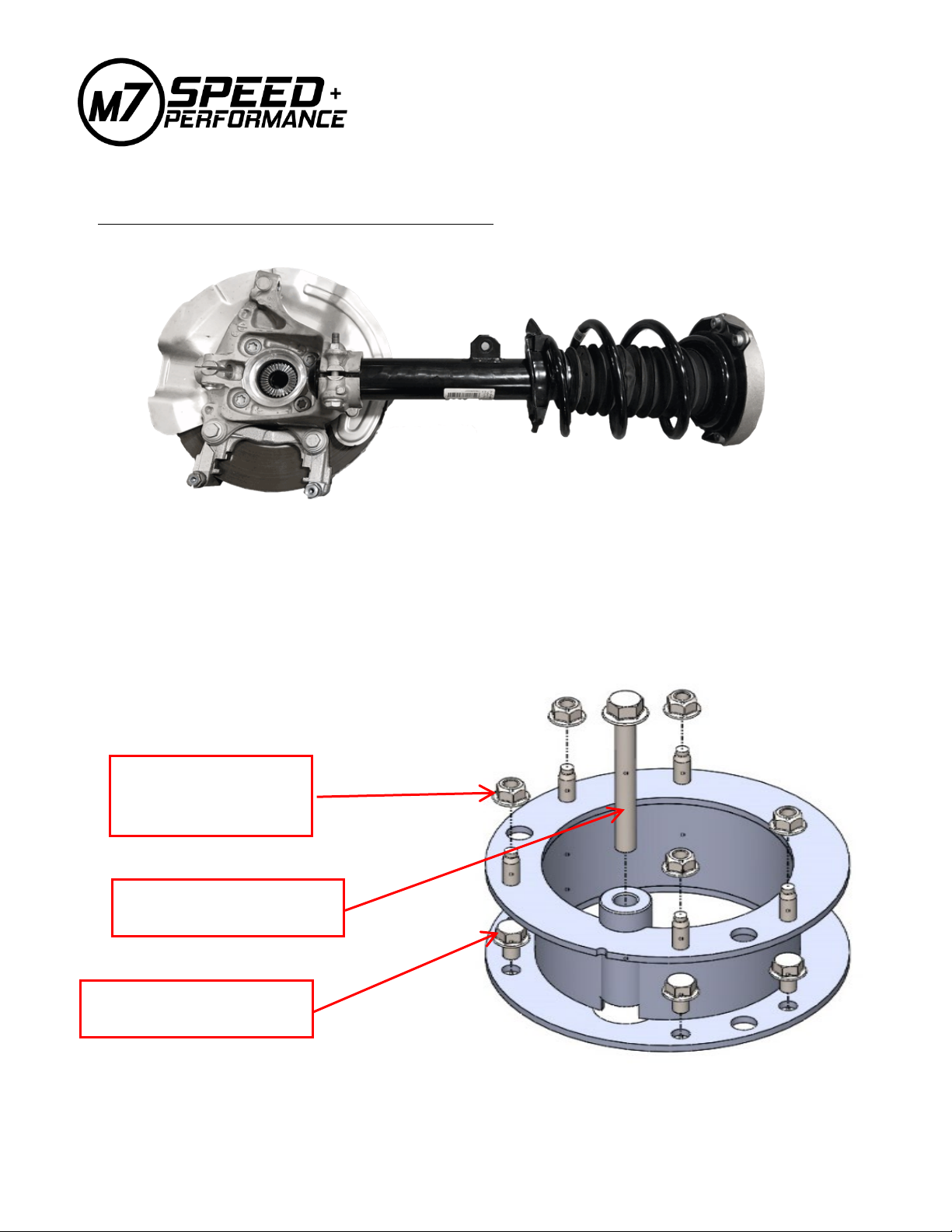
2. Install the strut assembly with the installed riser block into its location on the vehicle. Index the top using the M8
studs on the riser block to help with alignment.
3. Install the five M8 flanged lock nuts. Hand tighten only.
4. With the strut assembly hanging in the car and the lower swing arm free from the center pivot location insert
the steering tie rod pin and ball joint pin into the upright. Loosely install the OE fasteners. At the same time you
are doing this, pre-align the outer CV joint to the drive face and centerline of the hub.
5. Once the lower ball joint and steering tie rod pin are in place and secured, final align the outer CV joint with the
hub. Start threading in the CV drive bolt into the CV joint. Rotate the CV joint as you thread in the bolt to ensure
the drive teeth on the CV joint are aligned with the drive teeth on the hub. Snug up the bolt to remove all free
play.
6. Reposition and slide the lower swing arm pivot back into its OE mounting bracket. If it will not go back into
place easily chances are the drive axle slipped out of the inner CV joint. Slide the axle back into the inner CV
joint and finish aligning the pivot hole with the bolt hole. Excessive force should not be required. If it still will
not reassemble easily something is out of place or not assembled correctly. Double check all components to
verify correct assembly and alignment.
7. Once correctly aligned install the pivot bolt. Torque the OE pivot bolt to 75 lb-ft [100Nm] + 90 degrees rotation
(torque to yield)
8. Torque the outer steering tie rod end to 75 lb-ft [100Nm]
9. Torque the lower Ball Joint cross bolt to 45 lb-ft (60Nm)
10. Torque the CV drive bolt to 155 lb-ft [210 Nm] + 90 degrees rotation (torque to yield)
11. Reinstall the brake caliper, brake line bracket, headlight sensor bracket and wheel speed sensor. Verify
everything is tight and correctly torqued to OE specifications.
12. Install the MAXX-G Front sway bar links.
a. Set both links to the same length and lock the jam nuts.
b. Install one end into the front sway bar hole and the other end into the strut mounting bracket.
c. Place one thick washer on each stud.
d. Install the M10 castle nut. Torque to 30 lb-ft [40Nm]
e. Install the cotter pin.
13. Torque the five strut tower top nuts to 22 lb-ft [30Nm]. “DO NOT USE AN IMPACT GUN!”
14. Place the OE plastic strut top cover (if equipped) into its location sliding it over the chassis tie-bar.
15. Install the M7 supplied M10-1.25 x 80mm long Flange Head bolt through the chassis tie-bar and the M7 riser
block. Thread it into the OE strut plate. Torque to 40 lb-ft [55 Nm].
16. Repeat the complete front procedure for the other side of the vehicle.
NOTE: When both sides of the front suspension is completed safety check all
components for proper and complete installation and correct hardware tightness.

September 16, 2020 Page 10 of 12
17. Re-install the underside protective cover [8mm socket - 14 screws]
18. Install the plastic drip tray back into its location.
19. Install the under hood seal.
FINAL NOTES
AFTER INSTALLATION OF THIS KIT AND YOUR FINAL TIRES & WHEELS ARE INSTALLED A
COMPLETE 4 WHEEL ALIGNMENT IS REQUIRED TO SET THE TOE AND CAMBER TO FACTORY
SPRECIFICATIONS. IN ADDDITION AN A.D.A.S. (Advanced Driver Assistance Systems) ALIGNMENT IS
REQUIRED TO RECALIBRATE THE SYSEMS TO THE INCREASED VEHICLE HEIGHT.
YOUR MINI COUNTRYMAN IS NOW 2.5” HIGHER THAN THE FACTORY RIDE HEIGHT. THIS GIVES YOU
ADDED CLEARANCE WHEN USING YOUR CAR FOR ON AND OFF-HIGHWAY AND ALL-TERRAIN
ADVENTURE MOTORING SITUATIONS. IT ALSO MEANS YOUR MINI’S CENTER OF GRAVITY IS 2.5”
HIGHER. CORNERING AND HANDLING WILL BE ADVERSELY AFFECTED AND ROLL-OVER
SITUATIONS MAY OCCUR. FAILURE TO DRIVE THIS VEHICLE SAFELY MAY RESULT IN SERIOUS
INJURY OR DEATH. DO NOT DRIVE THIS VEHICLE UNLESS YOU ARE FAMILIAR WITH ITS UNIQUE
HANDLING CHARACTERISTICS AND ARE CONFIDENT OF YOUR ABILITY TO MAINTAIN CONTROL
UNDER ALL DRIVING CONDITIONS. SLOWLY GET RE-ACCUSTOMED WITH YOUR CAR’S HANDLING
AND ROAD BEHAVIOR CHARACTERISTICS BEFORE ATTEMPTING ANY AGGRESSIVE DRIVING.
WARNING: After installing this product the suspension of this vehicle will be
modified. As a result, the vehicle may handle differently than that of factory equipped
vehicles. As with any vehicle EXTREME CARE must be used to prevent loss of control or
roll overs during sharp turns or abrupt maneuvers. Always wear seat belts and drive
safely, recognizing that reduced speeds and specialized driving techniques may be
required with this vehicle. Failure to drive this vehicle safely may result in serious injury
or death. Do not drive this vehicle unless you are familiar with its unique handling
characteristics and are confident of your ability to maintain control under all driving
conditions. You are responsible for the safety and control of your vehicle at all times.

September 16, 2020 Page 11 of 12
SUPPLIMENTAL INFORMATION
FOR VDC (ELECTRONIC DAMPENING)
EQUIPPED VEHICLES
REAR SHOCK EXTENSION PLACEMENT
Insert M7 Rear Shock Spacer between the body and the
VDC Sensor (#3) / upper shock Mount (#5). Sensor wire
(#4) remains in OE position.
Use the factory OE bolts and supplied M8 Lock nuts
here. (Spacer to Shock Mount/VDC Sensor)
Use the new supplied M8
Flange bolts here. (Spacer to
Body)

September 16, 2020 Page 12 of 12
FRONT SPRING EXTENSION PLACEMENT
2
3
4
Insert the M7 Front spacer (#4) between the upper
spring mount (#2) and the strut tower mounting
points on chassis. Mount the VDC Sensor (#3) onto
strut per OE requirements. Route the VDC Sensor
wire (#5) through the center of M7 front spacer (#4)
and connect it to the vehicle loom. NOTE: If
additional wire length is needed to connect to the OE
loom reroute the chassis loom as required to gain
the needed length.
5
Table of contents
Other M7 SPEED Automobile Accessories manuals
Popular Automobile Accessories manuals by other brands

Fiamma
Fiamma CARRY-BIKE CARAVAN UNIVERSAL Installation and use instructions

Whispbar
Whispbar K390W Fitting instructions

Lippert Components
Lippert Components Sway Command Install manual

AUTOACCESS
AUTOACCESS Sport Cover SC-Z Mounting instructions

Cruz
Cruz E30-158 Assembly instructions

Rear view safety
Rear view safety RVS-776718-PS instruction manual