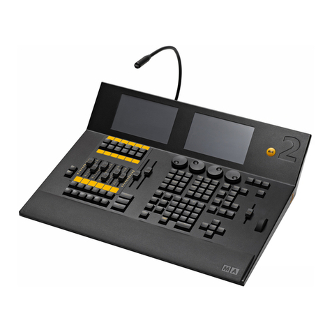
MA lighting MA Switch Setup guide

Grand MA
1
Repair Instructions grand MA

Grand MA
2
Repair Instructions grand MA
The following tasks may be performed by qualified personnel only! By disregarding the
instructions or the prescribed sequence of tasks the unit can be severely damaged. These
instructions are intended as a guide for qualified personnel.
Pull the mains plug before opening the unit. Disconnect the battery after opening the unit.
1. Replacing the hard disk drive / the DMX board
1.1. Pull the mains plug.
1.2. Remove the 10 connecting screws between lid and bottom section all around the unit
from below.
1.3. Remove the fastening screws on the back panel of the unit (see fig. 1).
1.4. Carefully tilt the lid upwards and support it with the red rod.
Warning: Do not tilt the lid beyond 90°! This could damage the plugs in the
unit's back panel.
1.5. Disconnect the battery.
1.6. Disconnect the ribbon cable of the PCB.
1.7. Remove the fastening screws of the PCB (see fig. 2).
1.8. Tilt the DMX board upwards and remove the 4 HDD screws. When installing the new
HDD, take care to reconnect the ribbon cable correctly. (please double-check!)
1.9. In case the DMX board has to be replaced, the remaining PCB cables have to be
disconnected, too.

Grand MA
3
1.10. The assembly is to be carried out – except the fastening screws – in the reverse
order. Carefully tighten the screws on the back panel first, and only then those on the
inner side of the unit.
2. Replacing the PC ATX board
2.1. Pull the mains plug.
2.2. Remove the 10 connecting screws between lid and bottom section all around the unit
from below.
2.3. Remove the fastening screws on the back panel of the unit and pull the plugs of the
keyboard and mouse cables (see fig. 3).
2.4. Carefully tilt the lid upwards, support it with the red rod and disconnect the battery.
Warning: Do not tilt the lid beyond 90°! This could damage the plugs in the
unit's back panel.
2.5. Disconnect all connecting cables – except those of the display adapters.
2.6. Remove the nut from the network adapter and pull out the adapter together with the
connecting board.
2.7. Remove the fastening screws of the PCB.
2.8. Now you can remove the PCB and pull out the graphic adapters. Since the graphic
adapters have different settings, they may not be interchanged. (pay attention
to the correct sequence!)
Warning! The display adapters may only be pulled out, if the PC ATX board had
been removed before!
2.9. The assembly is to be carried out – except the fastening screws – in the reverse
order. Carefully tighten the screws on the back panel first, and only then those on the
inner side of the unit. Take care not to over-tighten the nut of the network adapter!
3. Replacing a display adapter
Warning! The display adapters may only be pulled out, if the PC ATX board has
been removed beforehand!
Assemble the PCB as described above. (see also: 2nd replacement of the PC
ATX board!)
When replacing the display adapters, pay attention to the correct jumper settings, as
these are different for each adapter. Before removing the cable of the display adapter,
the plug has to be unlocked by pushing forward the 2 small clips by 1 mm.
4. Replacing the network adapter
4.1. Pull the mains plug.
4.2. Remove the 10 connecting screws between lid and bottom section all around the unit
from below.
4.3. Carefully tilt the lid upwards, support it with the red rod and disconnect the battery.
Warning: Do not tilt the lid beyond 90°! This could damage the plugs in the
unit's back panel.

Grand MA
4
4.4. Remove the nut from the network adapter on the back panel of the unit.
4.5. Remove the network adapter.
4.6. The assembly is to be carried out in the reverse order. Take care not to over-tighten
the nut of the network adapter!
5. Replacing a TFT display including touch screen
5.1. Pull the mains plug.
5.2. Remove the 10 connecting screws between lid and bottom section all around the unit
from below.
5.3. Carefully tilt the lid upwards, support it with the red rod and disconnect the battery.
Warning: Do not tilt the lid beyond 90°! This could damage the plugs in the
unit's back panel.
5.4. Lower the lid onto the bottom section and close it!
5.5. Tilt the display panel to the max. using the yellow ball knob.
5.6. Remove the screws on the back panel using a 2.5 mm Allen key. The lower screws
have to be unscrewed by only 2 turns. (see fig. 4)
5.7. Disconnect the electric cables of the defective display and remove the fastening
screws. Remove the knob and the fastening nut of the encoder on the front panel.
(see fig. 5)
5.8. Carefully remove the alloy tape.
5.9. In case the PCB has to be replaced, remove the 2 screws with the lock nuts. (see fig.
6)
5.10. Observe the following when assembling the touch screen to the display:
nThe components must be clean
nThe gluing points must be degreased
nPay attention to the correct position of the touch screen. In the front view, the
touch screen has to flush with the display on the right hand and bottom side
nCarefully apply new tape where needed
5.11. The assembly is to be carried out in the reverse order.
6. Replacing the pneumatic spring including hydraulic trigger
6.1. Pull the mains plug.
6.2. Remove the 10 connecting screws between lid and bottom section all around the unit
from below.
6.3. Carefully tilt the lid upwards, support it with the red rod and disconnect the battery.
Warning: Do not tilt the lid beyond 90°! This could damage the plugs in the
unit's back panel.
6.4. Remove the screws on the back panel using an Allen key. The lower screws have to
be unscrewed by only 2 turns. (see fig. 4)
6.5. Tilt display panel backwards completely. (standard position) For the following
assembly, remember or draw a sketch of how the tube is routed. Then, using a knife,
carefully cut the black shrinkdown tube open and remove it.
6.6. Remove the locking pin on the pneumatic spring and unhook the pneumatic spring.
Then, remove the hydraulic trigger using a 17 mm wrench.

Grand MA
5
6.7. If only the pneumatic spring is defective, replace it now by a new one. In this case,
the next step (6.8) can be omitted.
6.8. If the hydraulic trigger is defective, proceed as follows:
nRemove the yellow trigger knob. Holding the pin with pointed pliers, remove the
knob
nClose the lid and tilt the display panel upwards to max. 105° (see fig. 7)
Warning! Tilting the display panel over 105° may damage the electric cables in
the cable duct!
nRemove the 2 fastening screws of the trigger and replace the complete hydraulic
trigger for a new one Tighten the 2 fastening screws again
nCarefully tilt the display panel upwards. Make sure that the electric cable duct
does not jam on the underside!
Then, tilt the lid upwards again and support it with the red rod.
6.9. Now, screw the pneumatic spring into the seat of the hydraulic trigger. In order to
adjust the travel correctly, proceed as follows:
nWith one hand, screw the pneumatic spring into the trigger, and with the other
gently press on the trigger pin on the display panel. Screw-in the pneumatic spring
until the trigger pin has extended completely. Thereafter, turn back the pneumatic
spring for about ¼ turn. Tighten the pneumatic spring in this position, using a 17
mm nut.
nRotate the yellow ball knob on the display panel until a travel of 10 mm is reached
6.10. Slide a new shrinkdown tube over the pneumatic spring and the tube.
6.11. As a trial, hang up the pneumatic spring and check the settings by moving the display
panel. With proper settings, the shrinkdown tube can be warmed up. Excessive heat,
however, can damage the tube.
Pay attention to the correct position of the hydraulic tube!
Then, check the pneumatic spring again by moving it forward and backward.
6.12. Secure the pneumatic spring at the fastening points using the cotterpins.
6.13. The rest of the assembly is to be carried out in the reverse order.
7. Replacing the power supply
7.1. Pull the mains plug.
7.2. Remove the 10 connecting screws between lid and bottom section all around the unit
from below.
7.3. Remove the 4 fastening screws of the power supply on the bottom side of the
housing.
7.4. Carefully tilt the lid upwards, support it with the red rod and disconnect the battery.
Warning: Do not tilt the lid beyond 90°! This could damage the plugs in the
unit's back panel.
7.5. Disconnect the electrical cables on the power supply.
7.6. Remove the heat sinks from the old power supply and mount it to the new one.
7.7. Reinstall the new power supply.

Grand MA
6
7.8. Warning! When connecting and setting the voltage values, proceed as follows:
nFirst, plug in the mains voltage plug
nThen, only connect the resistor for the base load to the screw clips SK3 and switch
on the unit
nUsing setting screw 1 on the screw clips SK3, set the voltage value now to +5.35V
(see fig. 8)
nUsing setting screw 2 on pin 8 (SK2), set the value to +14,6V (see fig.8)
nReconnect the remaining plugs and cables
nCheck the voltage at the screw clips SK3 again and readjust the value if needed

Grand MA
7

Grand MA
8

Grand MA
9

Grand MA
10
Other manuals for MA Switch
1
Other MA lighting Dj Equipment manuals
MA lighting
MA lighting grandMA3 User manual

MA lighting
MA lighting grandMA3 User manual
MA lighting
MA lighting dot2 XL-F Installation guide

MA lighting
MA lighting grandMA3 User manual
MA lighting
MA lighting Dot 2 User manual

MA lighting
MA lighting grandMA3 User manual
MA lighting
MA lighting grandMA2 Series Manual

MA lighting
MA lighting Dot 2 User manual
MA lighting
MA lighting RJ-45 User manual
MA lighting
MA lighting dot2 XL-B Installation guide
