Mac Medical MDC-24 Manual

INSTRUC TIO N MA NUA L
Re a d a nd und e rsta nd a ll o f the instruc tio ns a nd sa fe ty
info rma tio n in this ma nua l b e fo re o p e ra ting this p ro d uc t.
MAN-086 Re v B 04/ 2019
© 2019 MAC Me d ic a l, Inc .
O PERATING RO O M C ABINETS
Insta lla tio n a nd Ma inte na nc e

Instruc tio n Ma nua l
MAN-086 2www .ma c me d ic a l.c o m
KEEP THIS MANUAL
DESC RIPTIO N O F PRO DUC T
This pro d uc ts c o ve re d in this ma nua l a re :
All typ e s a nd mo d e ls o f the sta inle ss ste e l O p e ra ting
Ro o m C a b ine ts.
Ta b le o f C o nte nts
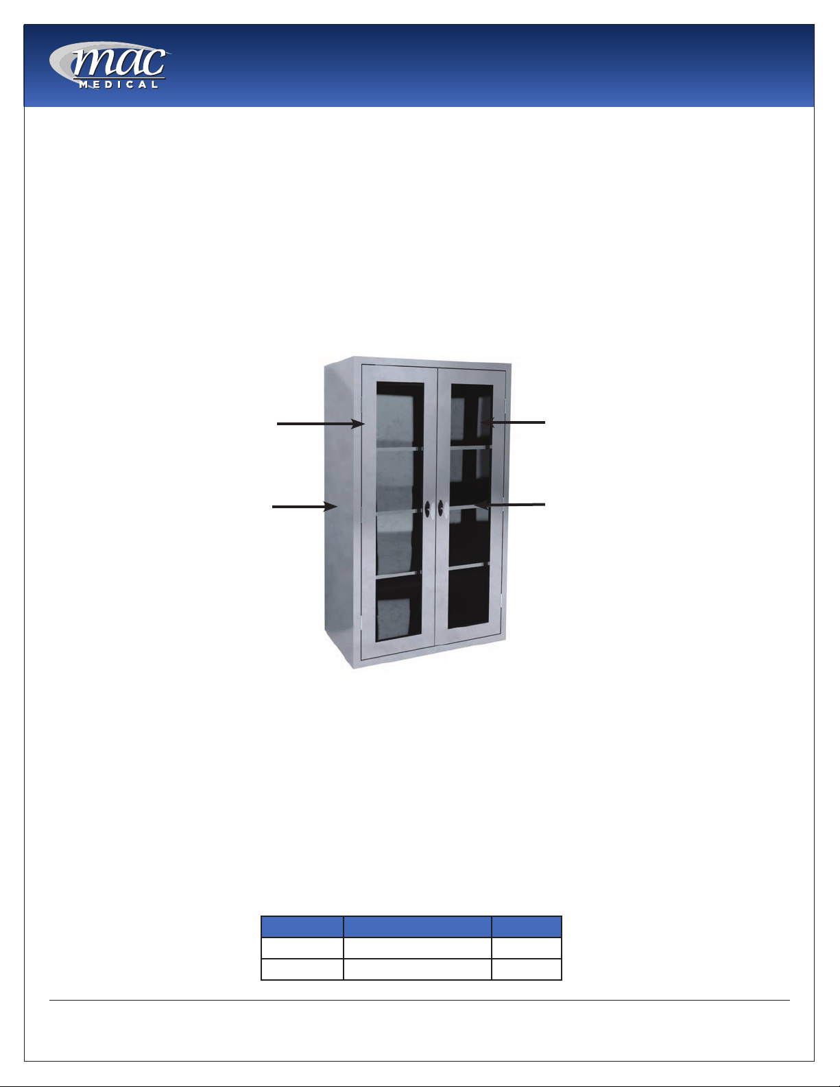
STA NDARD FEA TURES - MISC ELLA NEO US SUPPLY C A BINETS 3
Mo de l Num be rs a nd O ve ra ll Dim e nsions - Misc e lla ne ous Supply C a b ine ts 3
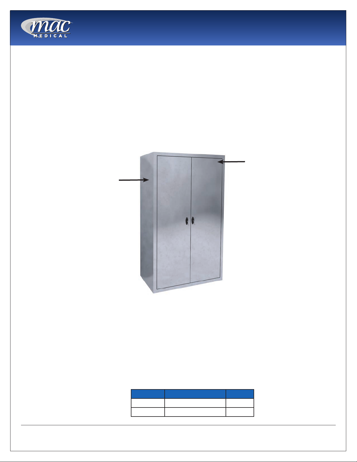
STA NDARD FEA TURES - EQ UIPMENT SUPPLY C ABINETS 4
Mo de l Num be rs a nd O ve ra ll Dim e nsions - Eq uipme nt Supply C a bine ts 4
STA NDARD FEA TURES - DESK C ABINETS 5
Mo de l Num be r a nd O ve ra ll Dim e nsions - De sk C a b ine ts 5
STA NDARD FEA TURES - TA BLE A C C ESSO RY C A BINETS 6
Mo de l Num be rs a nd O ve ra ll Dim e nsions - Ta ble Ac c e sso ry C a b ine ts 6
UNPA C KING A ND INSPEC TIO N INSTRUC TIO NS 8
INSTALLA TIO N REQ UIREMENTS 9
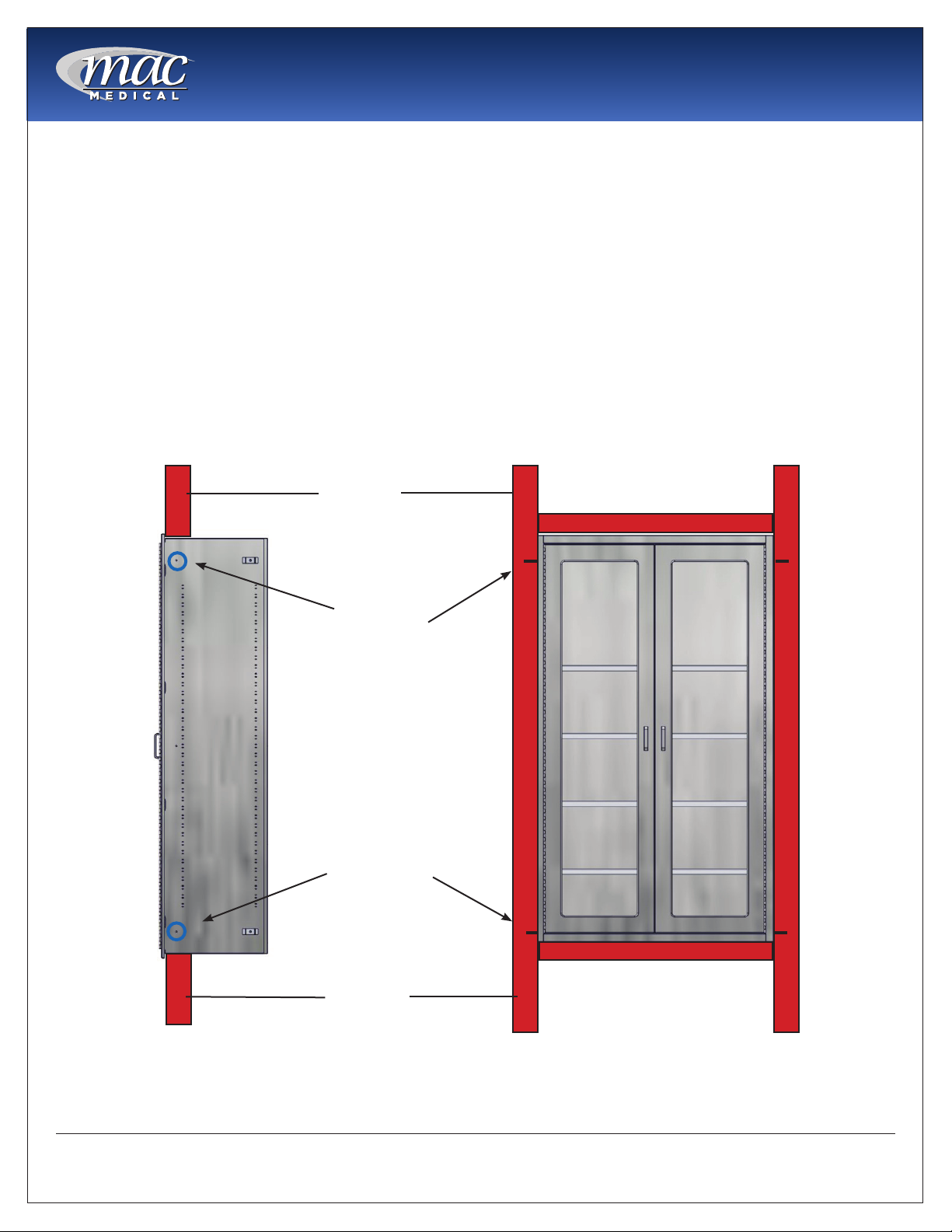
INSTA LLA TIO N INSTRUC TIO NS - REC ESSED C ABINETS 10
INSTA LLA TIO N INSTRUC TIO NS - BA NKED C ABINETS 11
INSTALLING O PTIO NAL SLO PED TO P - Wa ll Mo unte d C a b ine ts 13
INSTALLATIO N INSTRUCTIO NS - O ptio na l Wa ll Mo unte d O pe ra ting Ro om C a bine ts with se pa ra te Ba se s 14
INSTALLATIO N INSTRUCTIO NS - O ptio na l Wa ll Mo unte d O pe ra ting Ro om C a bine ts with pre - a sse mb le d b a se s 16
SHELF INSTALLA TIO N 18
ADJUSTING SHELVES 19
DO O R HING E ADJUSTMENT 20
O PTIO NA LELEC TRO NIC KEYPAD DO O R LO C K - PRO G RA MMING A ND O PERATIO N 21
Ba sic Info rm a tio n 21
Func tio ns 22
C o de s a nd C o de Le ve ls 22
Pro g ra m m ing 23
Ba tte ry Life a nd Ma inte na nc e 25
Lo st C o de p ro c e d ure 26
C LEA NING AND MA INTENA NC E 27
Lim ite d Life tim e Wa rra nty 28
PURPO SE O F THIS MA NUAL
This ma nua l p ro vid e s the use r with instruc tio ns o n the insta lla tio n a nd
ma inte na nc e o f b o th the Re c e sse d a nd Wa ll Mo unte d m o d e ls o f the the
va rio us sta inle ss ste e l Op e ra ting Ro o m C a b ine ts.
This ma nua l a lso c o nta ins the d e sc rip tio n o f the sta nd a rd fe a ture s a nd
general specications of the various models of Operating Room Cabinets.

Instruc tio n Ma nua l
MAN-086 3www .ma c me d ic a l.c o m
STA NDARD FEA TURES - MISC ELLA NEO US SUPPLY C A BINETS
Misc e llane o us Sup ply C ab ine ts c o m e standard with:
• Re c e sse d
• Sing le g la ss d o o r with 3/ 16” te mp e re d g la ss
• 3 a d justa b le sta inle ss ste e l she lve s
• Te e ha nd le
• Ma g ne tic d o o r c a tc he s with q uie t c lo se
• Se a mle ss fro nt fa c e
• Fully we ld e d c o nstruc tio n
• Typ e 300 se rie s sta inle ss ste e l
O p tio nal Fe ature s fo r Misc e llane o us Supply C ab ine ts:
• So lid sta inle ss ste e l d o o r
• Te e ha nd le with ke y lo c k
• Ele c tro nic ke yp a d d o o r lo c k with 4” sta nd a rd p ull ha nd le s
• Rig ht o r le ft hing e
• 12” hig h b a se (fo r wa ll mo unte d mo d e ls)
• Slo p ing to p (fo r wa ll mo unte d mo d e ls)
Mo de l Num be rs a nd O ve ra ll Dim e nsions - Misc e lla ne ous Supply C a b ine ts
Mo d e l # O ve ra ll Dime nsio ns She lve s
MMS-24 18” D x 24” W x 60” H 3
3/ 16” te mp e re d g la ss
Ad justa b le sta inle ss
ste e l she lve s
Fully w e ld e d
c o nstruc tio n

Instruc tio n Ma nua l
MAN-086 4www .ma c me d ic a l.c o m
STA NDARD FEA TURES - EQ UIPMENT SUPPLY C A BINETS
O p tio nal Fe ature s fo r Eq uipm e nt Supply C ab ine ts
• So lid sta inle ss ste e l d o o rs
• Te e ha nd le s with ke y lo c k
• Ele c tro nic ke yp a d d o o r lo c k with sta nd a rd ha nd le s
• 12” hig h b a se (fo r wa ll mo unte d mo d e ls)
• Slo p ing to p (fo r wa ll mo unte d mo d e ls)
Eq uip m e nt Sup ply C ab ine ts c o m e stand ard w ith:
• Re c e sse d
• Dua l g la ss d o o rs with 3/ 16” te mp e re d g la ss
• 3 a d justa b le sta inle ss ste e l she lve s
• Te e ha nd le
• Ma g ne tic d o o r c a tc he s with q uie t c lo se
• Se a mle ss fro nt fa c e
• Fully we ld e d c o nstruc tio n
• Typ e 300 se rie s sta inle ss ste e l
Mo de l Num be rs a nd O ve ra ll Dim e nsions - Eq uipme nt Supply C a bine ts
Mo d e l # O ve ra ll Dime nsio ns She lve s
MES-36 18” D x 36” W x 60” H 3
MES-48 18” D x 48” W x 60’ H 3
3/ 16’ te mp e re d g la ss
Ad justa b le sta inle ss
ste e l she lve s
Dua l g la ss d o o rs
Fully w e ld e d
c o nstruc tio n

Instruc tio n Ma nua l
MAN-086 5www .ma c me d ic a l.c o m
STA NDARD FEA TURES - DESK C ABINETS
O p tio nal Fe ature s fo r De sk C ab ine ts
• 12” hig h b a se (fo r wa ll mo unte d mo d e ls)
• Slo p ing to p (fo r wa ll mo unte d mo d e ls)
• C uVe rro ® Ba c te ric id a l C o p p e r 4” Pull Ha nd le s
De sk C ab ine ts c o m e standard with;
• Re c e sse d
• Slo p e d writing surfa c e
• Dry e ra se b o a rd
• 4 Dra we rs
• 4’ sta nd a rd p ull ha nd le s
• Se a mle ss fro nt fa c e
• Fully we ld e d c o nstruc tio n
• Typ e 300 se rie s sta inle ss ste e l
Mo de l Num be r a nd O ve ra ll Dim e nsions - De sk C a b ine ts
Mo d e l # O ve ra ll Dime nsio ns She lve s
MDC -24 18” D x 24” W x 60” H 0
Dry e ra se b o a rd
Slo p e d writing surfa c e
Fully w e ld e d
c o nstruc tio n

Instruc tio n Ma nua l
MAN-086 6www .ma c me d ic a l.c o m
STA NDARD FEA TURES - TA BLE A C C ESSO RY C A BINETS
O p tio nal Fe ature s fo r Tab le A c c e sso ry C ab ine ts
• G la ss d o o rs
• Te e ha nd le s with ke y lo c k
• Ele c tro nic ke yp a d d o o r lo c k with sta nd a rd ha nd le s
• 12” hig h b a se (fo r wa ll mo unte d mo d e ls)
• Slo p ing to p (fo r wa ll mo unte d mo d e ls)
Tab le Ac c e so ry C ab ine ts c o me standard with:
• Re c e sse d
• Dua l so lid d o o rs
• Pe g b o a rd b a c k a nd sid e s (1/ 4” d ia me te r ho le s)
• Te e ha nd le s
• Ma g ne tic d o o r c a tc he s with q uie t c lo se
• Se a mle ss fro nt fa c e
• Fully we ld e d c o nstruc tio n
• Typ e 300 se rie s sta inle ss ste e l
Mo de l Num be rs a nd O ve ra ll Dim e nsions - Ta ble Ac c e sso ry C a b ine ts
Mo d e l # O ve ra ll Dime nsio ns She lve s
MTA-36 18’ D x 36”W x 60’ H 0
MTA-48 18’ D x 48” W x 60” H 0
Dua l so lid d o o rs
Fully w e ld e d
c o nstruc tio n

Instruc tio n Ma nua l
MAN-086 7www .ma c me d ic a l.c o m
° This p ro d uc t is m a d e fro m a c o p p e r surfa c e tha t c o ntinuo usly kills b a c te ria * le ft b e hind b y d irty
ha nd s, killing mo re tha n 99.9% o f b a c te ria * within 2 ho urs.
La b o ra to ry te sting ha s sho wn tha t whe n c le a ne d re g ula rly this surfa c e :
° Kills mo re tha n 99.9% o f b a c te ria * within 2 ho urs, a nd c o ntinue s to kill 99% o f b a c te ria * e ve n a fte r
re p e a te d c o nta mina tio n.
° De live rs c o ntinuo us a nd o ng o ing a ntib a c te ria l* a c tio n, re ma ining e ffe c tive in killing g re a te r tha n
99.9% o f b a c te ria * within 2 ho urs.
° He lp s inhib it b uild up a nd g ro wth o f b a c te ria * within 2 ho urs o f e xp o sure b e twe e n ro utine c le a ning
a nd sa nitizing ste p s.
° Kills g re a te r tha n 99.9% o f G ra m -ne g a tive a nd G ra m-p o sitive b a c te ria * within 2 ho urs o f e xp o sure .
° C o ntinuo usly re d uc e s b a c te ria l* c o nta mina tio n, a c hie ving 99.9% re d uc tin within 2 ho urs o f e xp o sure .
* La b o ra to ry te sting sho ws tha t, whe n c le a ne d re g ula ry, C uVe rro surfa c e s kill g re a te r tha n 99.9% o f the fo llo wing b a c te ria
within 2 ho urs o f e xp o sure : Me thic illin-Re sista nt Sta p hylo c o c c us a ure us, Sta phylo c o c c us a ure us, Ente ro b a c te r a e ro g e ne s,
Pse ud o mo na s a e rug ino sa , E. c o li O 157:H7, a nd Va nc o myc in-Re sista nt Ente ro c o c c us fae c a lis (VRE).
The use o f C uVe rro ® b a c te ric id a l c o p p e r p ro d uc ts is a sup p le me nt to a nd no t a sub stitute fo r sta nd a rd infe c tio n c o ntro l
p ra c tic e s; use rs must c o ntinue to fo llo w a ll c urre nt infe c tio n c o ntro l p ra c tic e s, inc lud ing tho se p ra c tic e s re la te d to c le a ning
a nd d isinfe c tio n o f e nviro nme nta l surfa c e s. This surfa c e ha s b e e n sho w n to re d uc e mic ro b ia l c o nta mina tio n, b ut it d o e s no t
ne c e ssa rily p re ve nt c ro ss c o nta mina tio n.
C uVe rro ® is a re g iste re d tra d e ma rk o f G BC Me ta ls, LLC a nd is use d with p e rmissio n.
De sk C a b ine ts ma y b e o rd e re d with o p tio na l 4” Pull Ha nd le s ma d e with C uVe rro ® Ba c te ric id a l C o p p e r.
EPA C o mp a ny No . 92702-IL-1 EPA Re g istra tio n No . 92701

Instruc tio n Ma nua l
MAN-086 8www .ma c me d ic a l.c o m
UNPA C KING A ND INSPEC TIO N INSTRUC TIO NS
C AUTIO N: The O p e ra ting Ro o m C a b ine ts a re he a vy a nd it is re c o m m e nd e d tha t a t le a st
two p e o p le a ssist w ith the unp a c king .
Inspe c tio n
1. Re c e iving a re a must m e e t a ll Sta te a nd Lo c a l re g ula tio ns p rio r to unp a c king .
2. C usto me r must insp e c t skid a nd c a b ine ts b o th b e fo re a nd a fte r unp a c king to d e te rmine if a ny ite ms we re
d a ma g e d d uring ship p ing . If the skid o r c a b ine ts a p p e a r d a ma g e d in a ny wa y, c o nta c t the ship p ing
c o mp a ny imme d ia tly. Sa ve a ll d a ma g e d p a c king ma te ria l.
3. All d a ma g e d ite m s must b e liste d o n the Bill o f La d ing .
4. C usto me r is re sp o nsib le fo r the p ro p e r d isp o sa l o f a ll p a c king m a te ria ls. The d isp o sa l o f the se ite ms m ust
me e t a ll Sta te a nd Lo c a l re g ula tio ns.
Unp ac king O pe rating Ro o m C ab ine ts
Sta inle ss ste e l O p e ra ting Ro o m C a b ine ts a re ship p e d o n we ll-c o nstruc te d wo o d e n skid s. Ste e l b a nd s se c ure
the c a b ine ts to the skid . The sta inle ss ste e l surfa c e s o f the p a rt a re p ro te c te d b y la ye rs o f p la stc wra p p ing ,
a nd the c o rne rs a re p ro te c te d b y he a vy c a rd b o a rd .
IMPO RTANT: We a r g lo ve s a nd e ye we a r d uring the unp a c king o p e ra tio n.
1. Use tin snip s to c ut the me ta l b a nd s ho ld ing the b o x to the wo o d e n skid .
2. Re mo ve the c a rd b o a rd c o rne r p ro te c to rs.
3. Re mo ve the p la stic p ro te c tive w ra p p ing .
C a re fully insp e c t the O p e ra ting Ro o m C a b ine ts while unp a c king . If the y a p p e a r d a ma g e d o r d e fe c tive in a ny
wa y, c a ll yo ur MAC Me d ic a l re p re se nta tive .
Re ta in a ll ship p ing m a te ria ls until the c a b ine t is c o mp le te ly unp a c ke d a nd insp e c te d fo r d a ma g e .
C a utio n! Do no t use a b o x c utte r o r a ny o the r c utting ute nsil to re mo ve the p la stic wra p p ing
a ro und the c a b ine t. The se ite ms c a n sc ra tc h the p ro te c tive c o a ting o n the sta inle ss ste e l a llo wing
the surfa c e to rust.

Instruc tio n Ma nua l
MAN-086 9www .ma c me d ic a l.c o m
INSTALLA TIO N REQ UIREMENTS
The fo llo w ing instruc tio ns sho uld b e fo llo we d d uring the insta lla tio n o f a ny o f the O p e ra ting Ro o m
C a b ine ts:
• C he c k a ll lo c a l b uild ing c o d e s p rio r to insta lla tio n o f a ny o f the O p e ra ting Ro o m C a b ine ts.
• Do not lift the cabinets by their handles or by the anges in order to avoid damaging the
c a b ine ts.
• To p re ve nt c a b ine t d a ma g e , d o no t o ve rtig hte n the mo unting ha rd wa re .
• C a b ine ts must b e insta lle d sq ua re to insure p ro p e r d o o r fuc tio na lity.
• Install the Cabinets in their nal position. The Cabinets are difcult to move after assembly is
c o mp le te .
• O nly tra nsp o rt the C a b ine ts whe n the y a re e mp ty. Pro p e rly se c ure while b e ing tra nsp o rte d .
C a utio n! The va rio us C a b ine ts a nd the ir c o mp o ne nts a re he a vy. it is re c o mme nd e d tha t a t
le a st two p e o p le a ssist in the insta lla tio n o f the unit(s).
C a utio n! The Wa ll Mo unte d ve rsio ns o f the O p e ra ting Ro o m C a b ine ts c a n b e tip p ing
ha za rd s. It is re c o mme nd e d tha t the c a b ine ts b e a nc ho re d a g a inst the wa ll. Ho le s c a n b e
d rille d in the b a c k o f the c a b ine ts whe re ne e d e d a nd insta lle r p ro vid e d mo uting ha rd wa re
use d to se c ure the c a b ine ts a g a inst a wa ll.

Instruc tio n Ma nua l
MAN-086 10 www.m a c me d ic a l.c o m
INSTA LLA TIO N INSTRUC TIO NS - REC ESSED C A BINETS
The fo llo w ing a re b a sic instruc tio ns fo r the insta lla tio n o f Re c e sse d O p e ra ting Ro o m C a b ine ts.
1. Ve rify wa ll o p e ning size . Wid th a nd He ig ht o p e ning sho uld b e wid th o f the c a b ine ts m inus 1” . Fo r multip le
c a b ine t insta lla tio ns the wid th o f the o p e ning sho uld b e the to ta l fa c e wid th o f the c a b ine ts m inus 1” .
Exa mp le - C a b ine t He ig ht 80” = 79” o p e ning he ig ht.
C a b ine t Wid th - 36” = 35” o p e ning wid th
2. Shim o r b lo c k wa ll o p e ning a s re q uire d a nd inse rt the c a b ine t into the wa ll o p e ning .
3. For multiple banked cabinet installation, insert the cabinets in the wall opening in their desired conguration
a nd a sse mb le the m a s p e r the Ba nke d C a b ine t a sse mb ly instruc tio ns o n p a g e 11-12.
4. Se c ure c a b ine t with mo unting ha rd wa re thro ug h the p re p unc he d mo unting ho le s.
INSTALLER
PRO VIDED
MO UNTING
HARDWARE
PRE-PUNC HED
1/ 4” DIA.
MO UNTING
HO LES
Sid e Vie w Fro nt Vie w
Wa ll Stud s
Wa ll Stud s

Instruc tio n Ma nua l
MAN-086 11 www.m a c me d ic a l.c o m
INSTA LLA TIO N INSTRUC TIO NS - BA NKED C A BINETS
The se instruc tio ns a p p ly to b o th Wa ll Mo unte d a nd Re c e sse d
ve rsio ns o f the O p e ra ting Ro o m C a b ine ts.
C a b ine ts inte nd e d to b e Ba nke d will ship witho ut sid e p a ne ls
o n the sid e s whe re the y a re to b e jo ine d .
NO TE: Two Hig h C a b ine ts a re use d to illustra te this p ro c e d ure
(Fig . 1).
1. Ma ke sure tha t the c a b ine t is e m p ty a nd she lve s
re m o ve d b e fo re insta lling the b a nke d c a b ine ts. Re mo ve
the d o o rs p rio r to this o p e ra tio n (se e Fig . 5, p a g e 13).
2. If the C a b ine ts c o me with d e ta c he d Ba se s, a tta c h the
Ba se s to the C a b ine ts p e r the instruc tio ns o n p a g e s 14-15.
3. Place the rst cabinet in its desired location.
4. Lo c a te the 5 c o nne c tio n p o ints o n the sid e s o f e a c h
c a b ine t. Thre e c o nne c tio ns to wa rd the fro nt, a nd two
in the re a r (Fig . 2).
5. Pla c e 2 C o nne c tio n Sp a c e rs o n the c o nne c tio n p o ints
a t the re a r o f the c a b ine t, o ne o n the to p a nd o ne o n
the b o tto m (Fig . 3).
6. Place the next cabinet beside the rst cabinet, and align
the c a b ine t fa c e s.
7. Fro m the insid e o f o ne o f the c a b ine ts, inse rt the 1/ 4”
b o lt a nd o ne wa she r thru o ne o f the to p re a r c o nne c tio n
ho le s until it p ro trud e s fro m the o the r c a b ine t. Se c ure
with the wa she r a nd a c o rn nut. Re p e a t with the b o tto m
re a r c o nne c tio n ho le (Fig . 3).
Ac o rn nut a nd Wa she r
C o nne c tio n Sp a c e r
Bo lt a nd Wa she r
Fig . 1: Tw o c a b ine ts to b e b a nke d
Re a r c o nne c tio n p o ints
Fro nt c o nne c tio n p o ints
Fig . 2: C o nne c tio n Po ints
Fig . 3: Re a r Ba nk C a b ine t C o nne c tio n

Instruc tio n Ma nua l
MAN-086 12 www.m a c me d ic a l.c o m
8. Inse rt a 1/ 4” b o lt a nd o ne wa she r thro ug h o ne o f the
to p fro nt c o nne c tio n ho le s until it p ro trud e s fro m the
o the r c a b ine t. Se c ure with the w a she r a nd a c o rn nut.
Re p e a t with the c e nte r fro nt a nd b o tto m fro nt
c o nne c tio n ho le s (Fig . 4).
9. If the c a b ine ts a re Fre e Sta nd ing , a nc ho r the c a b ine ts
a g a inst the wa ll b y d rilling ho le s in the b a c k o f the
c a b ine ts whe re ne e d e d . Use insta lle r-p ro vid e d
ha rd wa re to se c ure the C a b ine ts a g a inst the w a ll.
10. Insta ll a ny she lve s a nd re p la c e the d o o rs.
INSTALLATIO N INSTRUC TIO NS - BANKED C ABINETS (c o nt.)
Ac o rn nut a nd Wa she r
Bo lt a nd Wa she r
Fig . 4: Atta c hing Ba nke d
C a b ine ts/ Fro nt C o nne c tio ns

Instruc tio n Ma nua l
MAN-086 13 www.m a c me d ic a l.c o m
Fig . 5: Lift d o o r fro m hing e s
INSTALLING O PTIO NAL SLO PED TO P - Wa ll Mo unte d C a b ine ts
If the c a b ine t is p urc ha se d with the o p tio na l Slo p e d To p , it will b e ne c e ssa ry to a tta c h the slo p e d to p to the
c a b ine t b e fo re m o unting the c a b ine t in its c ho se n lo c a tio n.
1. If the c a b ine t is e q uip e d with d o o rs, the y ma y
b e re mo ve d fo r e a se o f insta lla tio n. To re mo ve the
d o o rs, o p e n the d o o rs fully a nd lift the m o ff the ir
hing e s. The p in o n the hing e o f the d o o r will slid e o ut
o f the b a rre l o f the hing e o n the c a b ine t. (Fig . 5).
2. With the Do o rs a nd She lve s re mo ve d , c a re fully lo we r
the slo p e d to p o nto the to p o f the c a b ine t (Fig . 6).
3. Fro m within the c a b ine t, a tta c h the c a b ine t a nd
slo p e d to p using the fo ur 1/ 4” b o lts a nd wa she rs
(p ro vid e d ). Pla c e the wa she rs o ve r the b o lts a nd
inse rt the m into the fo ur ho le s in the to p o f the
c a b ine t a nd sc re w the m into the slo p e d to p (Fig . 7).
Fig . 6: Lo we r Slo p e d To p o nto C a b ine t Fig . 7: Atta c h Slo p e d To p to C a b ine t

Instruc tio n Ma nua l
MAN-086 14 www.m a c me d ic a l.c o m
INSTALLATIO N INSTRUCTIO NS - O ptio na l Wa ll Mo unte d O pe ra ting Ro om Ca b ine ts with se p a ra te Ba se s
1. If the O p e ra ting Ro o m C a b ine t is e q uip e d with
d o o rs, the y m a y b e re mo ve d fo r e a se o f insta lla tio n.
To re mo ve the d o o rs, o p e n the d o o rs fully a nd lift
the m o ff the ir hing e s. The p in o n the hing e o f the
d o o r will slid e o ut o f the b a rre l o f the hing e o n the
c a b ine t. (Fig . 8).
2. If the c a b ine t ship s with a se p a ra te b a se , p la c e the
b a se a t the d e sire d lo c a tio n fo r the c a b ine t. If Le g
Le ve le rs a re p ro vid e d w ith the b a se , use a le ve l a nd
the p ro vid e d wre nc h (Pa rt# IC 07-01) to a d just the
fo ur le g le ve le rs in the c a b ine t b a se until the b a se is
le ve l (Fig . 9)
3. It is re c o mme nd e d tha t the c a b ine t c a n b e furthe r
stabilized by attaching the base to the oor via holes
in the b o tto m o f the c a b ine t b a se (Ha rd wa re no t
p ro vid e d ) (Fig . 10).
4. Re mo ve c a b ine t b o tto m p a ne l -
C a b ine ts with Do o rs - re mo ve the two fro nt
fa c ing sc re ws ne a r the sid e s o f the c a b ine t.
Slid e the b o tto m p a ne l fo rwa rd a b o ut a n
inc h a nd re m o ve the p a ne l (Fig . 11).
O p e n-Fa c e d a nd Slid ing Do o r c a b ine ts -
Re mo ve the fo ur sc re ws fro m the to p o f the
b o tto m p a ne l (Fig . 12).
Lift the p a ne l up a nd o ut o f the c a b ine t.
(No te : Yo ur C a b ine t a nd / o r Ba se ma y va ry in a p p e a ra nc e
fro m the e xa mp le s sho wn in the se illustra tio ns).
Fig . 11: Re mo ve fro nt sc re ws Fig 12: Re mo ve 4 to p sc re ws
Fig. 10: Secure base to oor
Fig . 9: Ad just Le g Le ve le rs
Le g Le ve le rs
Wre nc h
Fig . 8: Lift d o o r fro m hing e s

Instruc tio n Ma nua l
MAN-086 15 www.m a c me d ic a l.c o m
INSTALLATIO N INSTRUC TIO NS - O p tio na l Wa ll Mo unte d O p e ra ting Ro o m C a b ine ts with se p a ra te Ba se s (c o nt.)
5. Pla c e the c a b ine t c a re fully o n the b a se (Fig . 13).
6. Se c ure the c a b ine t to the b a se using the Lo c king
He x Bo lts a nd Fla ng e d He x Nuts (p ro vid e d ) in the six
ho le s o n the sid e s o f the b a se a nd c a b ine t (Fig . 14).
7. Re p la c e b o tto m p a ne l o f the c a b ine t.
8. To furthe r se c ure the c a b ine t, ho le s ma y b e d rille d in the
b a c k o f the c a b ine t a nd insta lle r-p ro vid e d ha rd wa re use d
to se c ure the c a b ine t to the wa ll.
9. If the c a b ine t is e q uip e d with she lving p ro c e e d to the
She lf Insta lla tio n Instruc tio ns o n p a g e 18.
10. If the d o o rs ha ve b e e n re mo ve d , re p la c e the d o o rs b y
a lig ning the hing e s a nd g e ntly lo we ring the d o o r into the
hing e s. The p in o n the hing e o f the d o o r will inse rt into
the b a rre l o f the hing e o n the c a b ine t.
Fig . 14: Atta c h b a se a nd c a b ine t
Fig . 13: Mo unt C a b ine t to Ba se

Instruc tio n Ma nua l
MAN-086 16 www.m a c me d ic a l.c o m
INSTALLATIO N INSTRUCTIO NS - O ptio na l Wa ll Mo unte d O pe ra ting Ro om C a b ine ts with pre - a sse m b le d b a se s
Wa ll Mo unte d O p e ra ting Ro o m C a b ine ts c a n b e
e q uip p e d w ith Ad justa b le Le ve ling Fe e t. O nc e the
C a b ine t is p o sitio ne d whe re d e sire d , the Le ve ling Fe e t
ma y b e a d juste d a s fo llo ws:
C a b ine ts with Do o rs
1. For Cabinets with doors, it will be necessary to rst
re mo ve the d o o rs. O p e n the d o o rs fully a nd lift it
o ff its hing e s. The p in o n the hing e o f the d o o r will
slid e o ut o f the b a rre l o f the hing e o n the c a b ine t
(Fig . 15).
2. Afte r the d o o rs a re re mo ve d , re mo ve the two
fro nt fa c ing sc re ws ne a r the sid e s o f the c a b ine t
(Fig . 16)
3. Slid e the b o tto m p a ne l fo rwa rd a b o ut a n inc h
a nd re mo ve the p a ne l (Fig . 17).
4. Ad just the le ve ling fe e t w ith the Wre nc h p ro vid e d
(Pa rt # IC 07-01) (Fig . 18).
5. It is re c o mme nd e d tha t the c a b ine t b e furthe r
stabilized by attaching the base to the oor via holes
in the fro nt a nd b a c k o f the c a b ine t b a se (Ha rd wa re
no t p ro vid e d ).
6. Re p a c e the b o tto m p a ne l o f the c a b ine t.
Fig . 16: Re mo ve two fro nt sc re w s
Fig . 17: Re mo ve b o tto m p a ne l
Le g Le ve le r Wre nc h
Fig . 18: Ad just Le g Le ve le rs
Fig . 15: Lift d o o r fro m hing e s
7. If the d o o rs ha ve b e e n re mo ve d , re p la c e the d o o rs b y
a lig ning the hing e s a nd g e ntly lo we ring the d o o r into the
hing e s. The p in o n the hing e o f the d o o r will inse rt into the
b a rre l o f the hing e o n the c a b ine t.

Instruc tio n Ma nua l
MAN-086 17 www.m a c me d ic a l.c o m
O p e n Fa c e d C a b ine ts
8. Re mo ve the fo ur sc re ws fro m the to p o f the Bo tto m
Pa ne l (Fig . 19). Slid e the b o tto m p a ne l fo rw a rd
a b o ut a n inc h a nd re mo ve the p a ne l.
9. Ad just the le ve ling fe e t w ith the Wre nc h p ro vid e d
(Fig . 18).
10. It is re c o m me nd e d tha t the c a b ine t b e furthe r
stabilized by attaching the base to the oor via
ho le s in the fro nt a nd b a c k o f the c a b ine t b a se
(Ha rd wa re no t p ro vid e d ).
11. O nc e the c a b ine t is p ro p e rly le ve le d , re p la c e the
b o tto m p a ne l.
Fig . 19: Re mo ve 4 to p sc re ws
12. To furthe r se c ure the c a b ine t, ho le s ma y b e d rille d in the
b a c k o f the c a b ine t a nd insta lle r-p ro vid e d ha rd wa re use d
to se c ure the c a b ine t to the wa ll.
INSTALLATIO N INSTRUC TIO NS - O p tio na l Wa ll Mo unte d O p e ra ting Ro o m C a b ine ts with p re -a sse m b le d b a se s
(c o nt.)

Instruc tio n Ma nua l
MAN-086 18 www.m a c me d ic a l.c o m
SHELF INSTALLA TIO N
1. Insta ll the she lve s b y a tta c hing the She lf Sup p o rt
C lip s (4 p e r she lf; Fig . 20) into the ir d e sire d lo c a tio ns
b y inse rting the to p ta b into the up p e r wa ll slo t o f
tha t p o sitio n. Push up slig htly o n the inse rte d to p ta
a nd p ush the b o tto m ha lf o f the c lip in until the
b o tto m ta b sna p s into the lo we r slo t (Fig . 21).
2. C o unt the mo unting lo c a tio ns a t e a c h c o rne r o f
the c ha mb e r to b e sure tha t the she lf w ill b e le ve l
a nd insta ll the re m a ing sup p o rt c lip s.
3. Insta ll the she lf with the no tc he s o n the b o tto m o f
the she lf a lig ne d with the she lf sup p o rts (Fig . 22).
4. Pull o utwa rd o n the she lf to e nsure it is lo c ke d
p ro p e rly o n the sup p o rts.
5. If the d o o rs ha ve b e e n re mo ve d , re p la c e the d o o rs
b y a lig ning the hing e s a nd g e ntly lo we ring the d o o r
into the hing e s. The p in o n the hing e o f the d o o r will
inse rt into the b a rre l o f the hing e o n the c a b ine t.
Fig . 20: She lf Sup p o rt Ta b
Fig . 21: Atta c h 4 sup p o rt c lip s Fig . 22: Pla c e she lf o n Sup p o rt Ta b s

Instruc tio n Ma nua l
MAN-086 19 www.m a c me d ic a l.c o m
ADJUSTING SHELVES
1. Re mo ve the c a b ine t d o o rs if d e sire d fo r e a se
o f a d justme nt. O p e n the d o o rs fully a nd lift
the m o ff o f the ir hing e s. The p in o n the hing e o f
the d o o r will slid e o ut o f the b a rre l o f the hing e
o n the c a b ine t
2. Re mo ve the she lf a nd d e te rmine its ne w
p o sitio n (Fig . 23).
3. Re mo ve the fo ur (4 p e r she lf) she lf sup p o rts
c lip s b y tilting the c lip up wa rd s a nd lifting o ut
(Fig . 24).
4. Insta ll the she lf sup po rt into the ne w lo c a tio n b y
inse rting the to p ta b into the up p e r slo t o f the
ne w p o sitio n. Push up slig htly o n the inse rte d
to p ta b a nd p ush the b o tto m ha lf o f the c lip in
until the b o tto m ta b sna p s into the lo we r slo t.
5. C o unt the m o unting lo c a tio ns a t e a c h c o rne r
o f the c ha mb e r to b e sure tha t the she lf will b e
le ve l a nd insta ll the re ma ining sup p o rts.
6. Re -insta ll the she lf with the no tc he s o n the
b o tto m o f the she lf a lig ne d with the she lf
sup p o rts.
7. Pull o utwa rd o n the she lf to insure it is lo c ke d
p ro p e rly o n the sup p o rts.
8. If the d o o rs we re re m o ve d p rio r to she lf
a d justme nt, the y ma y no w b e re -insta lle d b y
a lig ning the hing e s a nd g e ntly lo we ring the
d o o r into the hing e s. The p in o f the hing e o n
the d o o r will inse rt into the b rre l o f the hing e o n
the c a b ine t.
Fig . 23: Re mo ve she lf fro m sup p o rt ta b s
Fig 24: Re mo ve 4 Sup p o rt Ta b s a nd re lo c a te

Instruc tio n Ma nua l
MAN-086 20 www.m a c me d ic a l.c o m
If the d o o r fra me s a p p e a r misa lig ne d , it will b e ne c e ssa ry to a d just the d o o r hing e s to e nsure tha t the d o o r
fra me s a lig n c o rre c tly.
1. O p e n o ne d o o r fully a nd lo o se n the sc re ws o n the hing e s tha t a tta c h to the sid e s o f the c a b ine t (2 sc re w s
p e r hing e ) (Fig . 25)
2. Mo ve the d o o r up o r d o wn (up to 1/ 4” in e ithe r d ire c tio n) to a lig n o ne d o o r fra me with the o the r (Fig . 26).
Use a le ve l to e nsure the d o o r fra me s a lig n p ro p e rly.
3. Tig hte n the hing e sc re ws whe n d e sire d a lig nme nt is a c hie ve d .
DO O R HING E ADJUSTMENT
Up p e r Hing e a tta c he d
to Do o r
Lo o se n sc re ws o n Lo w e r
Hing e a tta c he d to c a b ine t
Fig . 25: Lo o se n Hing e Sc re ws
Ad just d o o r fra m e up o r d o wn
Fig . 26: Ad just d o o r up o r d o wn
This manual suits for next models
5
Table of contents
Other Mac Medical Indoor Furnishing manuals
Popular Indoor Furnishing manuals by other brands

Seville Classics
Seville Classics airLIFT OFF65927 manual

all33
all33 BackStrong C1 Assembly instructions

Triarch
Triarch 31132 Assembly instructions

Tavolo
Tavolo 411/78.1100.22E Assembly instructions

Onespace
Onespace 50-JN15L05 Assembly instructions

Birlea
Birlea CORONA 2+2 DRAWER CHEST Assembly instructions

Rev-A-Shelf
Rev-A-Shelf 486-30VSBSC-BM-1 quick start guide

Leggett & Platt
Leggett & Platt LPConnect user guide

Moduspace
Moduspace MAX150 Assembly guide

Kring
Kring AZIK221 Assembling Instruction

Living & Co
Living & Co WHISTLER 4 DRAWER TALLBOY Assembly instructions

Lightolier
Lightolier Calculite R7029 specification