Mac Medical WT0004 User manual

INSTRUCTION MANUAL
Read and understand all of the instructions and safety
information in this manual before operating this product.
MAN-070 REV A 03/2018
© 2017 MAC Medical, Inc.
WORK TABLES
(Manual and Electric Height Adjust)

Instruction Manual
MAN-070 2www.macmedical.com
KEEP THIS MANUAL
DESCRIPTION OF PRODUCT
This manual covers MAC Medical Work Tables wth
Manual or Electronic Height Adjust Options.
PURPOSE OF THIS MANUAL
This manual covers the operation and
maintenance of the Mac Medical Work
Tables with the Manual or Electronic
Height Adjust Options.
Table of Contents
STANDARD FEATURES - WORK TABLES 3
Optional Features of the Work Tables: 3
Model Numbers and Overall Dimensions 3
GENERAL SPECIFICATIONS 4
Table Installation 4
UNPACKING INSTRUCTIONS 5
MINIMUM/ MAXIMUM ADJUSTABLE HEIGHTS FOR A WORK TABLE 6
HEIGHT ADJUSTMENT - MANUAL HYDRAULIC PUMP WITH HANDCRANK 7
HEIGHT ADJUSTMENT - MOTORIZED ADJUSTABLE HYDRAULICS 8
Work Tables with Electroic Adjustable Height Option - Control Panel Technical Data 8
Work Tables with Electronic Adjustable Height Option - Control Panel Setup and Operation 9
Replacing the Memory Control Pad 11
Installing the Replacement Memory Control Pad 12
Programming the Replacement Memory Control Pad 13
Instructions for Cleaning Stainless Steel Tables 14
Replacement Parts - General 15
Limited Lifetime Warranty 16

Instruction Manual
MAN-070 3www.macmedical.com
STANDARD FEATURES - WORK TABLES
MAC Medical Work Tables come Standard with:
• Fully welded construction
• Reinforced stainless steel top (16 gauge type
300 series)
• Stainless steel under shelf (18 gauge type 300
series)
• 2” square legs
• Added supports
• 5” Casters (2 Swivel & 2 Locking)
Optional Features of the Work Tables:
• Ergonomically friendly adjustable heights, adjustable manually or electronically.
• Manual adjustable height range: 36” - 55”
• Electronic adjustable height range: 36” - 43”
• H or U brace instead of Under Shelf
• Full base unit underneath
• Drawers under all sizes
• Stainless steel guard rails
• Multiple under shelves
Model Numbers and Overall Dimensions
Model Number Overall Dimensions
Depth Width Height
WT0003 36 24 36
WT0004 48 24 36
WT0005 60 24 36
WT0054 72 30 36
WT0055 72 36 36
WT0059 60 30 36
5” Casters
Manual height
Adjust (Optional)
Reinforced stainless steel top
H brace
(optional)

Instruction Manual
MAN-070 4www.macmedical.com
GENERAL SPECIFICATIONS
Power Requirements:
120 Volt, 60 Hz, single phase, 15 amp GFCI protected electrical outlet, installed per local building codes, and
provides protective grounding.
UL Approved:
All individual electronic components are UL approved and/or recognized.
Table Installation
Work Tables with the Electronic Height Adjustment Option require a power source to operate the hydraulics
system.
1. Place the table so that its left side(where its power unit is located) is near a 120 VAC GFI power outlet.
2. Plug in the table cord.
3. On the initial start-up, set the maximum and minimum heights on the control pad as shown on page 9
and 10.
4. After the initial start-up and control pad setting, thereafter simply use the up or down arrow buttons on the
control pad to raise or lower the height of the table.

Instruction Manual
MAN-070 5www.macmedical.com
UNPACKING INSTRUCTIONS
Inspection
1. Receiving area must meet all State and Local
regulations prior to unpacking.
2. Customer must inspect skid and Table both before
and after unpacking to determine if any items
were damaged during shipping.
3. All damaged items must be listed on the Bill of
Lading.
4. Customer is responsible for the proper disposal of
all packing materials. The disposal of these items
must meet all State and Local regulations.
Unpacking the Work Table
Work Tables are shipped on well-constructed wooden
skids. Two steel bands secure the Table to the skid.
The stainless steel surfaces of the part are protected
by heavy carbboard end-caps, and by layers of
plastic wrapping.
Care must be taken while unpacking the table to
avoid damage. Do not drop tools on the table or
scratch the surfaces with sharp edges.
IMPORTANT: Wear gloves and eyewear during the
unpacking operation.
Retain all shipping materials until the table is
completely unpacked and inspected for damage.
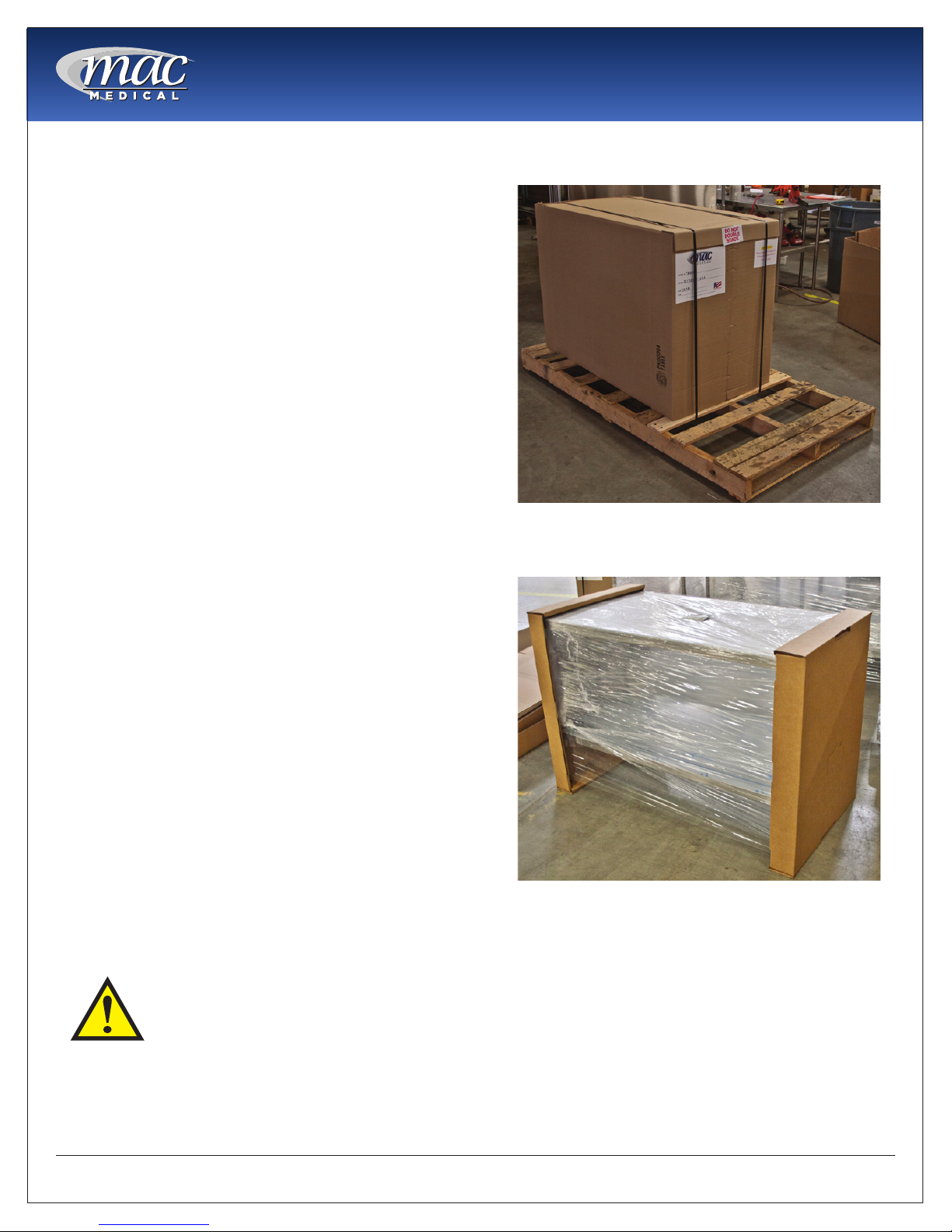
5. Use tin snips to cut the metal bands holding the
box to the wooden skid (Fig1).
6. Remove metal staples holding one end of the
packing carton together.
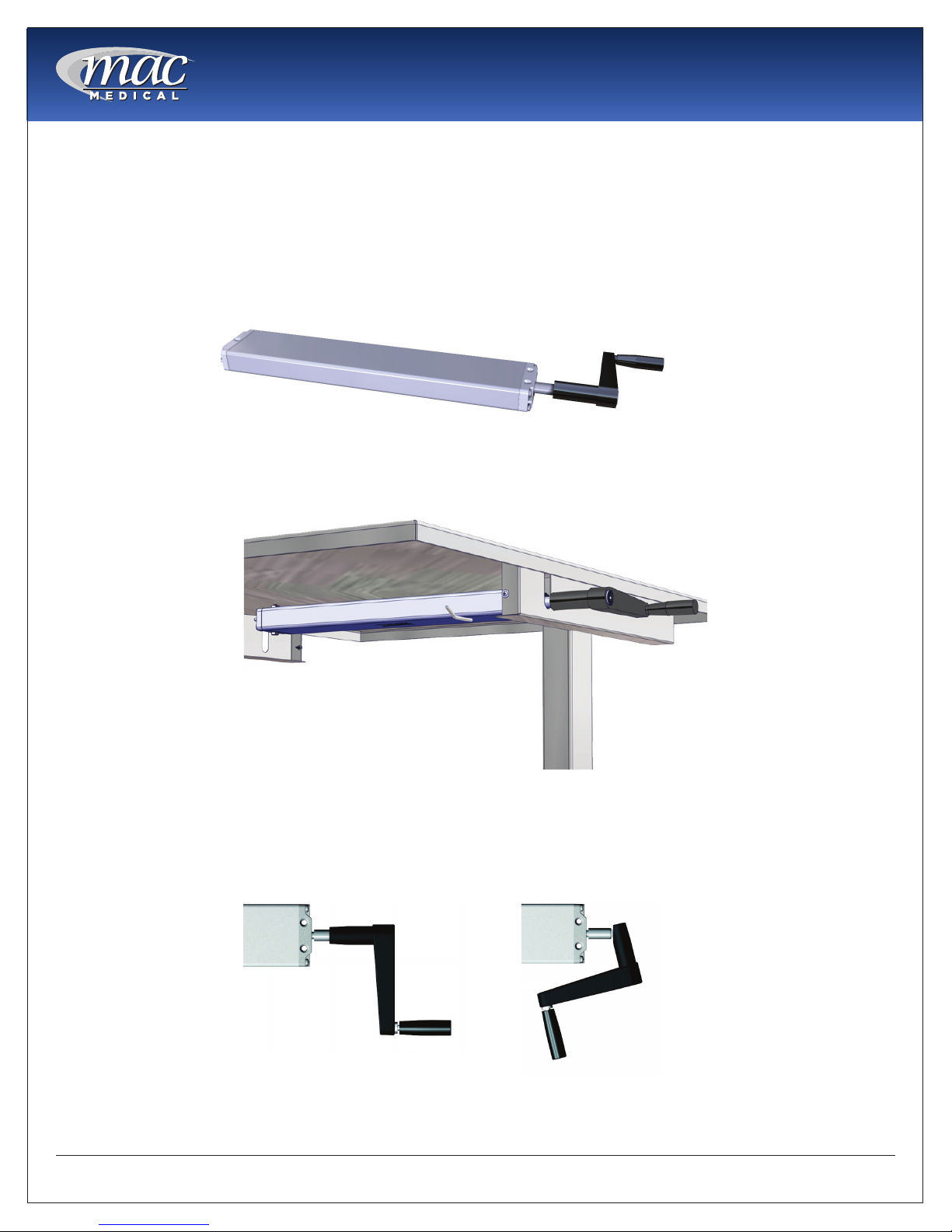
7. Slide out table from side of packing carton with
two attached cardboard end caps (Fig 2).
8. Remove 2 cardboard end caps.
9. Remove the plastic protective wrapping.
Caution! Do not use a box cutter or
any other cutting utensil to remove
the plastic wrapping around the table.
These items can scratch the protective
coating on the stainless steel allowing
the surface to rust.
10. The Work Table is now ready for use.
11. Discard shipping and packing materials in
compliance with state and local regulations.
12. When not in use, tables must not be double
stacked while in storage. While still in their
shipping cartons, tables must not be double
stacked when not in use.
Fig. 1: Boxed Table
Fig. 2: Wrapped table with end caps.

Instruction Manual
MAN-070 6www.macmedical.com
MINIMUM/ MAXIMUM ADJUSTABLE HEIGHTS FOR A WORK TABLE
Minimum/ Maximum Adjustable Height, Manual Height Adjustment
TheMinimumheightofaManualHeightAdjustWorkTableis36”(fromoortotabletop).
TheMaxumimheightofaManualHeightAdjustWorkTableis55”(fromoortotabletop).
Minimum/ Maximum Adjustable Height, Electronic Height Adjustment
TheMinimumheightofanElectronicAdjustWorkTableis36”(fromoortotabletop)
TheMaximumheightofanElectronicHeightAdjustWorkTableis43”(fromoortotabletop).
55”
Fig. 3: Manual height adjust minimum/ maximum heights.
Fig 4: Electronic height adjust minimum/ maximum heights.

Instruction Manual
MAN-070 7www.macmedical.com
HEIGHT ADJUSTMENT - MANUAL HYDRAULIC PUMP WITH HANDCRANK
For Space Saver Tables equipped with the Optional Manual Hydraulic Pump with Handcrank (Fig. 5-6), the
Handcrank can be folded to disappear under the table.
1. Crank the table to the desired height
2. Pull the Crank outwards, then rotate downward to fold the handle under the table (Fig. 7).
Fig. 5: Manual Hydraulic Pump with Handcrank
Fig. 7: Hydraulid Pump Handcrank unfolded and folded.
Fig. 6: Hydraulic Pump and Handcrank Location.

Instruction Manual
MAN-070 8www.macmedical.com
Work Tables with Electroic Adjustable Height Option - Control Panel Technical Data
The Control Panel feature is available for a Work Table with the Electronc Adjust Option to operate its
hydraulics.
Features ElectricalSpecications
4 Memory Positions Primary Voltage 120V, 10A
Digital Display of the height Engine Voltage 24 VDC
Overload Protection Nominal Rating Approximately 340 VA
Thermal Protection Standby Power <0.6W
Nominal Speed 180 min-1
Protection Type IP 20
HEIGHT ADJUSTMENT - MOTORIZED ADJUSTABLE HYDRAULICS
Electric Motor with
Hydraulic Pump
Memory Control Pad
Power Supply
Fig 8: Memory Control Pad, Power Unit, Electric Motor and Hydraulic Pump

Instruction Manual
MAN-070 9www.macmedical.com
Work Tables with Electronic Adjustable Height Option - Control Panel Setup and Operation
Attherstpower-on,followthesesteps:
Note: US customers will see the values in the display in terms of US inches. European customers will see display
values in terms of EU Centimeters.
1. First start up
a. Thedisplaywillinitiallyash“027”(US)or“068”(EU).
b. Pressthe“Down”arrowbutton(seeillustrationabove)untilthelowerUS:36”/EU:91cmendpositionis
reached, checking with a tape measure
c. The table moves down with half speed. Moving up is not possible.
d. AdjustthereadoutinUSinches/EUcentimeterstoreecttheactualheightwiththe“1”button(plus)
andthe“2”button(minus).
e. Moving up or down is not possible.
f. Pressthe“S”(greenbutton)toconrm.
g. AftertheconrmationthedisplaywillashUS:”036”/EU:”091”.
h. Usethe“Up”arrowbuttontomovetotheupperus:43”/EU:109cmupperlimit,checkingwithatape
measure.
i. The table will move at half speed and half power.
j. AdjustthereadoutinUSinches/EUcentimeterstoreecttheupperpositionwiththe“1”button(plus)
andthe“2”button(minus).
k. Conrmwiththe“S”button.
l. Afterconrmationthedisplaywillash“109”.
m. AftertheconrmationtheheightisshownandtheControlBoxisreadyfornormaloperation.
2. Operation up / down
a. Pressthe“Down”arrowbuttonorthe“Up”arrowbuttonuntilthedesiredheightofthetablehasbeen
reached.
b. The display always shows the actual height in US inches or EU centimeters
c. The table moves as long as the key is pressed, or until the end position is reached.
Fig. 9: Memory Control Keypad

Instruction Manual
MAN-070 10 www.macmedical.com
3. Saving of a position
a. This function allows the user to save a particular operating height on one of the four preset buttons.
b. Pressthe“S”button(Display:“5–“).
c. Pressoneofthefollowingbuttons:“1”,“2”,“3”,or“4”.
d. Afterhavingpressedoneofthepositionbuttonslistedabove,an“S”andoneofthepositionbuttonsis
readonthedisplay(i.e.“S3”).
e. Attheendofthememoryprocedure,adouble“Click”isheardandafter2secondstheactualheightis
readonthedisplay(i.e.“073”).
f. If there is a power failure or the unit is unplugged, the programmed pre-sets are retained (up to 24
hours).
4. Reset of the Control Unit
a. Pressandhold“1”,“2”,andthe“Up”arrowatthesametimeuntilitashes“S5”.Thecontrolisnowin
the adjustment mode.
• Release“1”,“2”,andthe“Up”arrow.PresstheUparrowuntilthedisplayshows“S7”.Thenpress“S”
to set.
b. Then press the down arrow. The table will now move down. Checking with a tape measure, lower the
table down to US:36’’/EU: 91cm.
c. Thenhold“2”untilitreads“000”.
• Thenpress“S”toset.Itwillthendisplay“036”.
d. Hold the Up arrow to US:43’’/EU:109cm (check the height with the tape measure).
• Thenpress“1”untilitreads“109”.Thenpress“S”toset.
5. Setting of Indicated Height
a. Pressthe“S”button.Displaywillread“5–“.
b. If the key is not pressed within 5 seconds, the control returns to standard mode again.
c. Pressthe“Down”arrowbuttonnowforabout5secondsuntilthedisplaystartsashing.(Example:
displayashes:“073”).
d. Theheightcanalsobesetwiththe“Up”(plus)orwiththe“Down”(minus)arrowbuttons.Duringthis
procedure the table does not move.
e. Ifthepositioniscorrectlyset,thenewheightcanbesavedbypressingthe“S”button.
• Thepositionissavedandthedisplaystopsashing.
• Thenewheightisalsosaved,ifnobuttonispressedwithin5secondsthedisplaystopsashing
automatically.
Work Tables with Electronic Adjustable Height Option - Control Panel Setup and Operation (continued)

Instruction Manual
MAN-070 11 www.macmedical.com
Replacing the Memory Control Pad
Removing the Existing Memory Control Pad
IftheMemoryControlPadmustbereplaced(duetodamage),rstremovetheexistingMemoryControlPad:
1. UNPLUG THE TABLE FROM ITS POWER SOUCE.
2. Remove four 1/4” screws attaching the Controller to the table mounting plate (Fig. 10).
3. Unplug the old Memory Control Pad cord from the Power Supply Unit.
4. Remove the old Memory Control Pad.
Fig. 10: Remove old Memory Control Pad

Instruction Manual
MAN-070 12 www.macmedical.com
Installing the Replacement Memory Control Pad
1. Position the replacement Memory Control Pad on the mounting plate under the front edge of the table.
Align the four holes in the control panel with holes in table mounting plate.
2. Insert four 1/4” screws into the holes of the Memory Control Pad, attaching the Memory Control Pad to the
table mounting plate. (Fig. 11)
3. Plug the control pad cable into the round
receptacle of the table Power Supply Unit ( 12-
13).
4. Plug the table cord back into its power source.
5. Program the Replacement Memory Control Pad
as shown on page 13.
Item # Part # Description QTY
1 H0090-PBD-110 Memory Control
Pad 1 with power
cord
1
2 H0203 4-40 X 1/4”” Screw
With Internal Tooth-
Lock Washer
4
Fig. 12: Plug in Memory Control Pad cord to Power unit
Fig. 13: Power Unit receptacle (viewed from back of table)
Fig. 11: Attach new Memory Control Pad

Instruction Manual
MAN-070 13 www.macmedical.com
Programming the Replacement Memory Control Pad
After the new Memory Control Pad has been installed, it must be programmed.
1. PressandholdButtons“1”,“2”,andthe“UP”Arrowatthesame
time. The Memory Control Pad is now in the adjustment mode.
2. ReleaseButtons“1”,“2”,andthe“UP”arrow.Pressthe“UP”arrow
untilthedisplayreads“S7”.
3. Next,pressthe“S”button.
4. Pressthe“DOWN”Arrow.Thetablewillnowmovedown.Verify
height of table is US:36”/EU:91cm with a tape measure.
5. Pressandhold“2”buttonuntil“000”isdisplayed.PressGREEN
(SET)Button.Displaywillnowread“036”.
6. Pressandhold“UP”ArrowuntilthetableraisestoUS:43”/EU:91cm.
Verify height of table is 43” with a tape measure.
7. Pressandhold“1”buttonuntilthedisplayreads“109”.Next,press
the“S”button.
8. The Memory Control Pad is NOW ready for use.
HOLD AT THE
SAME TIME
RELEASE
BUTTONS
PRESS UP ARROW
PRESS SET BUTTON
PRESS SET (GREEN) BUTTON
HOLD BUTTON #2 DISPLAY READS 000
PRESS SET (GREEN) BUTTON
PRESS #2 BUTTON
HOLD UP ARROW
HOLD BUTTON #1
PRESS SET BUTTON

Instruction Manual
MAN-070 14 www.macmedical.com
Instructions for Cleaning Stainless Steel Tables
Stainless Steel tables must be cleaned on a regular basis to prevent any unnecessary damage to the stainless
steel surfaces.
When cleaning stainless steel tables, make sure to use the proper approved cleaning agents and cleaning
materials.
CAUTION
DO NOT USE these Cleaning Materials
CAUTION
DO NOT USE these Cleaning Agents
Abrasive Pads Hard Water (water with a pH reading above 7.0).
Scrapers Hydrochloric Acid
Steel Wool Steam or high pressure water
Wire Brushes Bleach or any compounds containing chlorine or Soldium
hypochlorate, or ammonium chloride salts.
Approved cleaning materials and agents
• Soft, clean lint-free cloth
• Non-abrasive cleaning pads
• Soft bristle brush
• Mild detergents
• Sodium Bicarbonate (baking soda)
• Distilled water (pH rating 7) alone or with a mild detergent
• White vinegar (in a spray bottle)
• Isopropyl Alcohol
• Hospital-grade non-bleach disinfectants
• Cleaners approved for use on stainless steel
Cleaning Stainless Steel Surfaces
1. Using a damp, lint-free cloth and approved cleaner, wipe down the entire exterior surface of the stainless
steel table. Using a damp, lint-free cloth with distilled water and a mild detergent, wipe down the entire
exterior surface of the stainless steel table.
2. Let the cleaned table air dry.
Cleaning Decals or Printed Labels
• Use only distilled water and a mild detergent applied with a clean, dry lint-free cloth to clean decals or
printed labels.
• Cleaning agents can remove or smear any printing from decals and print labels.
• Cleaning agents can damage plastic materials used in manufacturing covers for electronic items such as
touch-screen pads.

Instruction Manual
MAN-070 15 www.macmedical.com
Replacement Parts - General
Item ID Part Number Description QTY. Models
1 H0135-5-SS 5” Swivel Caster 2 All
1 H0135-5-LSS 5” Swivel Caster w/Brake 2 All
2 H0090-03 Hydraulic Pump with crank 1 All
1
2
2
TheWorkTablereplacementpartslistedonthispagehavebeenidentiedbyMACMedicalasserviceable
byfacilitypersonnelandareavailableforpurchase.ToobtainMACMedicalcertiedpartsandauthorized
services, contact your MAC Medical representative.

Corporate Ofce
325 West Main Street
Belleville, IL 62220
Manufacturing Plant
820 South Mulberry Street
Millstadt, IL 62260
Phone: 618-476-3550 • Toll Free: 877-828-9975 • www.macmedical.com
MAC Medical, Inc.
Printed in USA
Publication No. MAN-070 Rev A
March 2018
Information regarding this product is
subject to change without prior notice.
Customer needs are our rst priority.
To place an order, contact our customer service
department at 618-476-3550 or 877-828-9975 or
Limited Lifetime Warranty
MAC Medical warrants to the original purchaser that its Proprietary Products will be free from
defects in workmanship or materials under normal use and service for the life of the product, so
long as owned by the original purchaser, according to the limitations set forth below.
Defective products shall be repaired or replaced at MAC Medical’s option at no cost to the
original purchaser provided:
1. The customer must obtain a written return authorization supplied by MAC Medical’s
customer service department. The product must be returned, properly packaged, with a
copy of the original sales receipt and copy of the RMA authorization. Please call (877) 828-
9975 or (618) 476-3550 to receive a return authorization.
2. The customer must pre-pay freight charges to and from MAC Medical and must ship
merchandise properly packaged, in a way the product will not be damaged during transit
to the factory. MAC Medical does not warranty any freight damage to or from the factory. It
is the customer’s responsibility to inspect the product for packaging damage before signing
the BOL.
This warranty does not apply to products, which have been subject to abuse, misuse, accident,
modication,alteration,tampering,negligence,lackofroutinemaintenanceormisapplication;
or products that have been repaired by other than MAC Medical or its authorized
representatives.
This warranty does not apply to glass, fabrics, vinyl, seat coverings, cushions, padding or their
stitching, gluing or installation. Component parts not manufactured by MAC Medical, such
as casters, caster inserts, any components made from rubber or plastic, circuit boards, fan
heaters, plumbing parts, electrical switches and other components are also excluded. For
these component parts, MAC Medical will pass on the original manufacturer’s warranty to
MAC Medical equipment original purchasers. Please consult factory for questions regarding
the warranties of these component parts. This warranty does not apply to custom fabricated
products. Consult factory.
UNLESS EXPRESSLY SET FORTH IN THIS WARRANTY, THERE ARE NO OTHER WARRANTIES, WHETHER
EXPRESS OR IMPLIED, OF FITNESS AND / OR MERCHANTABILITY OR ANY OTHER WARRANTY IMPLIED
BY CUSTOM, USAGE OR COURSE OF DEALING.
Liability of MAC Medical under this warranty is limited to the repair and / or replacement of any
products.MACMedicalspecicallyexcludesanddisclaimsanyresponsibilityforanyincidental
or consequential damages claimed to have arisen from any defect in workmanship or materials.
No representative has any authority to change or enlarge the above warranty or MAC Medical
liability. This document supersedes all previous warranty provisions.
This manual suits for next models
5
Table of contents
Other Mac Medical Indoor Furnishing manuals
Popular Indoor Furnishing manuals by other brands

adeptus
adeptus 77246 Assembly instructions

Bretford
Bretford ec7000 Assembly instructions

Fif Möbel
Fif Möbel VITRINE Assembly instructions

Livarno Living
Livarno Living 283347 Assembly instruction

Bob's Discount Furniture
Bob's Discount Furniture ELEVATIONS 20070173 Assembly instructions

5five
5five 173678 instruction sheet