MacDonald Steel Limited
BREWERY SYSTEMS DIVISION
4 REV 00
CONTROLS
POWER ON/OFF
Side panel – main power to machine. Circuit breaker(s) are also located directly below the power
switch. When tripped a visible red line appears on the breaker button. Also inside the machine on
the terminal blocks are fuse(s) which protect the PLC outputs and fuse(s) protecting the 24 VDC
power supply.
STOP SWITCH
(Red) Stops all operations on all heads. All heads lift and shuttle forward. This switch also acts
as a master reset switch. At any time if held for 2 seconds, the heads and door will rise, and the
shuttles return to the front position.
On multi-head machines, there is a stop switch for each head on the Human Machine Interface
(HMI), which allows independent heads to be stopped.
START SWITCH
(Green) When pushed the door will go down and the machine will begin the selected cycle.
MANUAL STOP SWITCH:
These stop switches are accessed via the HMI display. When the HMI main screen is being
displayed, the stop buttons will stop each bottle independently. Pushing the stop button a second
time will lift the head immediately.
MANUAL CROWN SWITCH:
These crown switches are accessed via the operator display. When the HMI main screen is
being displayed there is a button for each crowner.
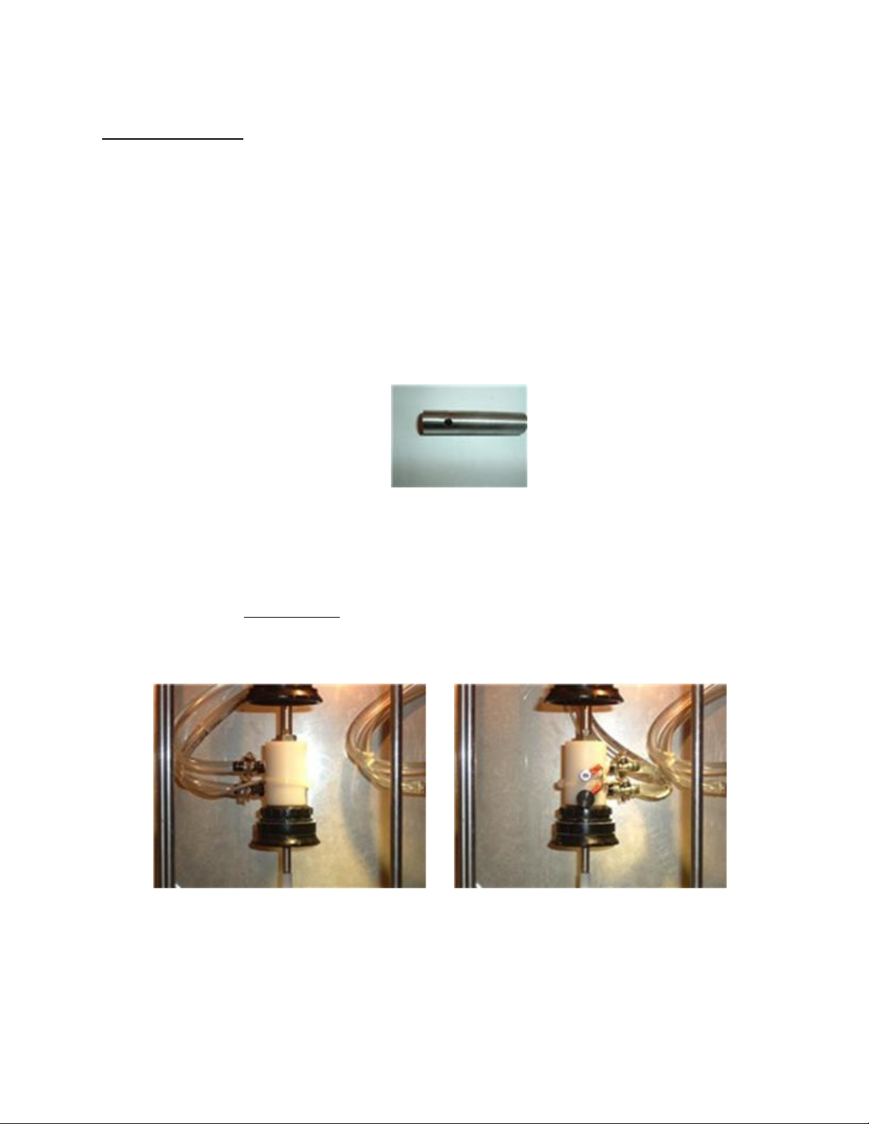
ANALOG PRESSURE TRANSDUCERS
One for each head, these switches control the pressure for the Co2 pressure and the vacuum
draw.
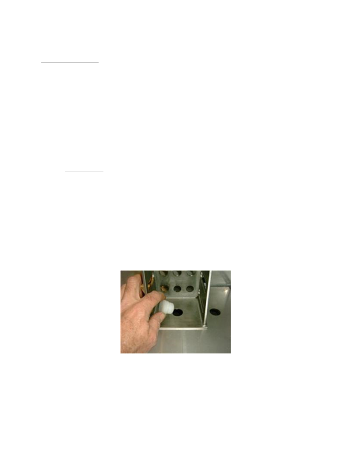
VENT CONTROL
Stainless steel flow controls, one for each head, located at the lower left side of the machine.
These control the rate of pressure released from the bottle and thus the fill rate of beer.
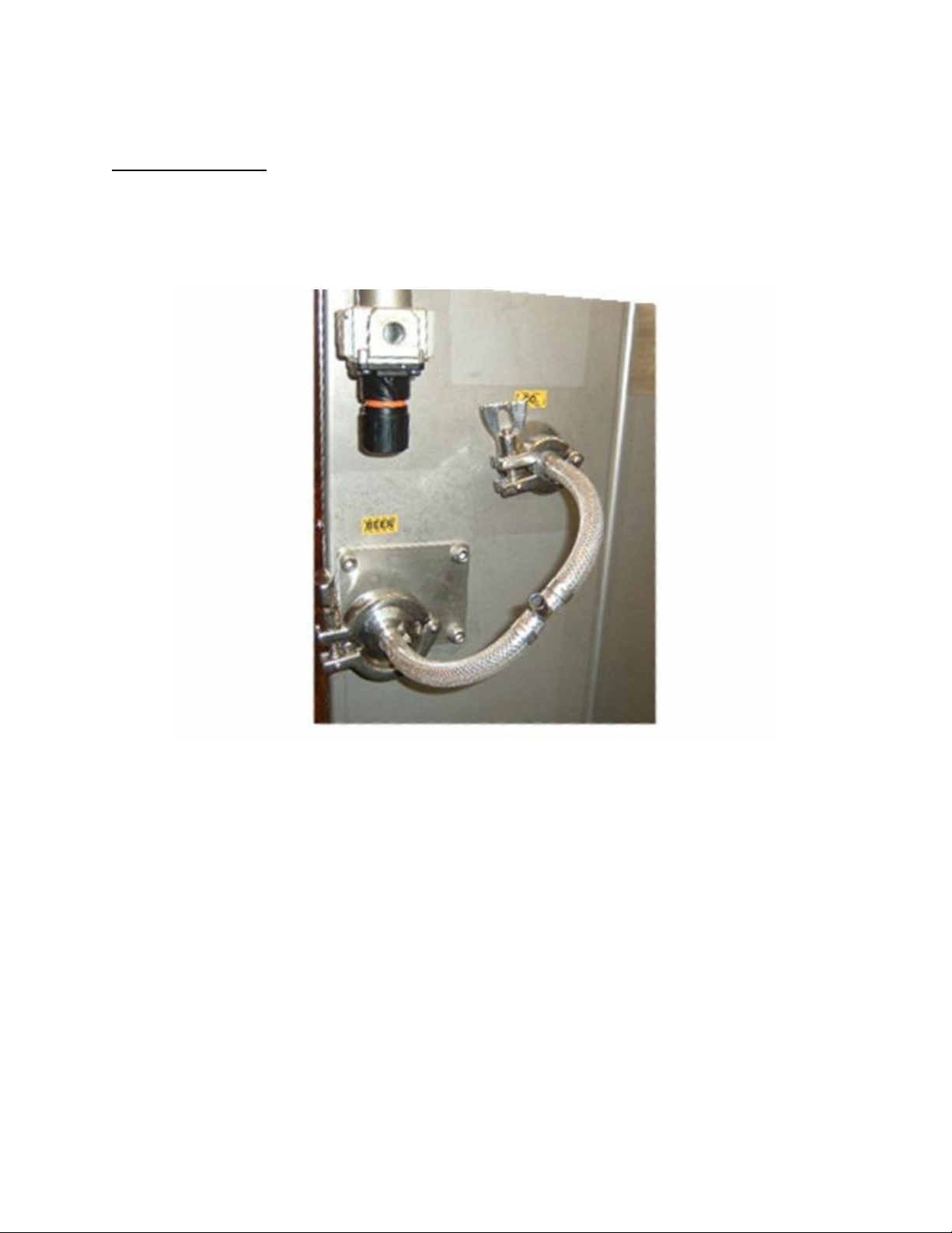
AIR REGULATOR
Set the regulator to 60 psi as a starting point. The crowning cylinders require the most force and
the pressure may have to be increased to ensure a good crown. The vacuum is a venturi style
and uses air to achieve vacuum. If you require a deeper vacuum you may have to increase the
air pressure as well. The air components in the machine should not be exposed to water or oil,
install a good quality filter before the machine. The maximum air pressure should not exceed 90
psi. The lower the pressure the longer life expectancy of the air components.
Co2 REGULATOR
The Co2 regulator (not supplied) is to be set dependant on the pressure in the beverage supply
tank. When the EZ Pressure set up measures the tank pressure the Co2 counter pressure is
automatically set to 2 psi higher than the tank reading. The set point value is displayed on the
bottom of the pressure screen when the Co2 valve is opened. The Co2 regulator must be able to
achieve that value. It is recommended to set the regulator between 5 to 10 psi higher than the
tank pressure. Setting the regulator too high could result in false or unstable measurements as
the valve opens and Co2 surges into the pressure transducer.