Macnaught M3OKT316-KT User manual

Instruction Manual
REV 03/07/23
WARNING:
Read carefully and understand all INSTRUCTIONS before operating. Failure to follow the safety
rules and other basic safety precautions may result in serious personal injury.
Save these instructions in a safe place and on hand so that they can be read when required.
Keep these instructions to assist in future servicing.
3:1 Mobile Oil Dispensing Kit
M3OKT316-KT
M3OKT355-KIT

GENERAL SAFETY REGULATIONS
WARNING: The warnings, cautions, and instructions
discussed in this instruction manual cannot cover all
possible conditions or situations that could occur. It
must be understood by the operator that common
sense and caution are factors that cannot be built into
this product, but must be supplied by the operator.
1. Keep the work area clean and dry. Damp or wet work areas can result in
injury.
2. Keep children away from work area. Do not allow children to handle this
product.
3. Use the right tool for the job. Do not attempt to force small equipment to do
the work of larger industrial equipment. There are certain applications for
which this equipment was designed. It will do the job better and more safely
at the capacity for which it was intended. Do not modify this equipment, and
do not use this equipment for a purpose for which it was not intended.
4. Check for damaged parts. Before using this product, carefully check that it
will operate properly and perform its intended function. Check for damaged
parts and any other conditions that may affect the operation of this product.
Replace damaged or worn parts immediately.
5. Do not overreach. Keep proper footing and balance at all times to prevent
tripping, falling, back injury, etc.
6. DO NOT use the equipment when tired or under the influence of drugs,
alcohol, or medication. A moment of inattention while operating this
equipment may result in serious personal injury.
WARNING SYMBOL: This manual contains important warnings and
information.Read and keep for reference.
CAUTION SYMBOL: This symbol alerts you to the possibility of serious
injury or death if you do not follow the instructions.
CAUTION: This symbol alerts you to the possibility of damage to or
destruction of equipment if you do not follow the instructions.

E1
TECHNICAL DETAILS
LIMITED WARRANTY
1. Macnaught warrantees this product against defects in material and craftsmanship, for a
period of 3 years from date of purchase, but not including wearing parts.
2. Macnaught’s liability is limited to replacement or repair of defective material within the
warranty period, when returned freight prepaid to the distributor or their designated service
depot.
3. The warranty does not cover damage caused by accident, misuse or faulty installation.
4. The product must be installed and maintained in compliance with the instructions.
Product Description
Pump
Trolley
Oil Nozzle
Connection Hose
Item No. M3OKT316-KT
3:1 Mobile Oil Dispensing Kit 13-16 Gallon
P/N:OP163-1-001
P/N:M3TR5
P/N:18123522
1/2"x13FT
M3OKT355-KIT
3:1 Mobile Oil Dispensing Kit 48-58 Gallon
P/N:OP583-1-001
P/N:M3TR205
P/N:18123522
1/2"x13FT
Including

E2
INSTALLATION STEPS
Note: Before connecting and assembling each component, please assemble each
component according to the component instructions).
1. Assemble the trolley (part No. 1) according
to its instruction manual.
1. Install the pump (part No. 2) into the
corresponding fixing hole of the trolley.
Step 1 Step 2
1
1
2
1. Tighten the female thread of delivery hose
(part No.3) with the male thread of pump
outlet.
1. Tighten the male thread of delivery hose
(part No.4) with the female thread of oil
control valve (part No.4).
Step 3 Step 4
2
1
3
2
3
1
4

E3
EXPLODED VIEW AND DETAILS
QTY
1
1
1
1
Description
Trolley
Oil Pump
Delivery Hose Assembly
Oil Control Valve
* Wearing parts.
Part No.
1
2
3*
4
3
2
1
4
4
2
1
3
M3OKT316-KT
M3OKT355-KIT

E4
TECHNICAL DETAILS - TROLLEY ASSEMBLY
DRUM TROLLEY EXPLODED AND PARTS LIST -
M3OKT316-KT
Item No.
M3TR5 385mm
Drums DiameterDrums Capacity
5-16Gallon
Part No.
1
2
3
4
5
6
7
8
9
10
Description
Screw
Trolley Top
Handle
Handle Cover
Drum Support
Adjustable Cover
Adjustable Pole
Hexagon Bolt
Handle Wheel
Accessory
Q’ty
1
1
1
1
1
1
1
2
3
1
Part No.
11
12
13
14
15
16
17
18
19
20
Description
Blocker
M6 Bolt
Washer
M8 Bolt
Washer
Wheel
Swivelling Wheel
Acorn Nut
Washer
Washer
Q’ty
1
2
2
2
2
2
2
2
2
2

E5
TECHNICAL DETAILS - TROLLEY ASSEMBLY
DRUM TROLLEY EXPLODED AND PARTS LIST -
M3OKT355-KIT
Part No.
1
2
3
4
5
6
7
8
9
Description
Accessories
Drum holder support
Handle
Pump support
Hexagon screw set
Stopper
Accessories support
Acom nut
Washer
Q’ty
1
1
1
2
3
1
1
2
2
Part No.
10
11
12
13
14
15
16
17
Description
A swivelling wheel
Hexagon bolt
Washer
Wheel
Axle
Hexagon bolt
Trolley top
Hexagon screw set
Q’ty
2
2
2
2
2
2
1
2
Item No.
M3TR205 600mm
Drums DiameterDrums Capacity
48-58Gallon

E6
TECHNICAL DETAILS - OIL PUMP ASSEMBLY
SAFETY INSTRUCTIONS
When the pump is connected to the compressed air supply:
1. The compressed air must be filtered to avoid dust and moisture into pump.
2. The max compressed air pressure must not exceed 1.0Mpa/150psi.
3. To deliver oil, press the knob on the delivery pistol; delivery stops when the knob is released
but the whole system remains under pressure.
4. Position the pistol so that the circuit can’t open accidentally. Otherwise oil could leak onto
the ground.
5. Never point the pistol at people or object.
6. Press the pistol knob.
7. Always cut off the air supply after use so that oil can’t leak out in case one of the pump’s
components should break.
8. Use only original spare parts in case the pump has to be repaired or its components have to
be replaced.
9. Empty all the oil from the pump in case it has to be disposed of.
10. When not in use, turn off compressed air to stop pump.
11. Do not use the pump near open flames. Do not smoke during this operation.
12. Wear oil-proof gloves.
13. Do not throw the oil away. Used oil has to be disposed of according to national
environmental regulations.
14. The pumps can be used only to deliver lubricants, used oil or antifreeze liquids. Do not use
the pump for any other substance.
THE MANUAL OF OIL PUMP
Read the following precautions and instructions before you begin assembly or using.
Failure to comply with these instructions could result in personal injury or property damage.
Keep these instructions in a convenient location for future reference.
IMPORTANT NOTE
The guarantee will be void if the pump has been altered in any way.
PROFILE
Oil pumps can be used to transfer lubrication oil, waste oil and antifreeze liquids.
This manual is applicable to the following pump only, please confirm your pump is included.
Item No.
Drum Application
Pressure Ration
Air Inlet Pressure
Max.fluid Pressure
Air Motor Effective Diameter
Air Consumption (Per Minute)
Max. Free Flow Rate (Per Minute)
Suction Tube Diameter
Suction Tube Length
Suction Tube Material
Air Inlet Connection
Oil Outlet Connection
OP163-1-001
13-16gallon
3:1
30~150psi
450psi
2-1/2"
3.6CFM @150psi
5.28gallon
1-5/8"
28-3/4"
Carbon Steel
1/4"NPT female
1/2"NPT male
OP583-1-001
48-58gallon
3:1
30~150psi
450psi
2-1/2"
3.6CFM @150psi
5.28gallon
1-5/8"
37"
Carbon Steel
1/4"NPT female
1/2"NPT male

E7
TROUBLE SHOOTING
If the pump has anything wrong, please contact dealer or their technical supporter.
We don’t recommend customer repair the pump themselves.
STORAGE AND MAINTENANCE
Pumps are delivered in appropriate carton boxes. Packaging material should be properly
disposed.
Handling and storage of the new pump do not require any special procedures.
However after the pump has been used, empty the used oil in the suction tube into an
appropriate container. This is done by overturning the pump.
The dust in compressed air can slow down and even block the motor cylinder. The following
steps may prevent this from happening:
1. Let in 50 gram of Vaseline oil or other lubricator from the air inlet hole weekly, operate the
pump for several minutes after having lubricator.
2. Turn on the pump for several minutes until moving parts is fully lubricated.
3. You may repeat the above operation if necessary.
4. The above steps should be carried out on a weekly base.
For the pumps that are attached with compressed air treatment equipment, please empty the
water retained in the reservoir of the filter-purger frequently.
For the pumps that are attached with a lubricator, please pay close attention to the lubricator’s
oil level and refill with SAE 20, SAE 30 or antifreeze oil for extreme conditions when necessary.
NOTE:
The user should perform only routine maintenance operations (such as filters, silencers,
cleaning…) with the pump in order not to damage it or compromise its safety.
Contact our sales or service center when the pump needs further maintenance.
Problem
The Pump can’t work
Leak of pneumatic device
The pump is unstable
The pump can work, but the
output flow is low
Oil leaks through the air exhaust
SolutionsPossible Causes
1. Insufficient air
2. Air obstruction
1. The intake valve is closed
2. The intake valve is blocked
A blockage in a hose, valve, or
other device
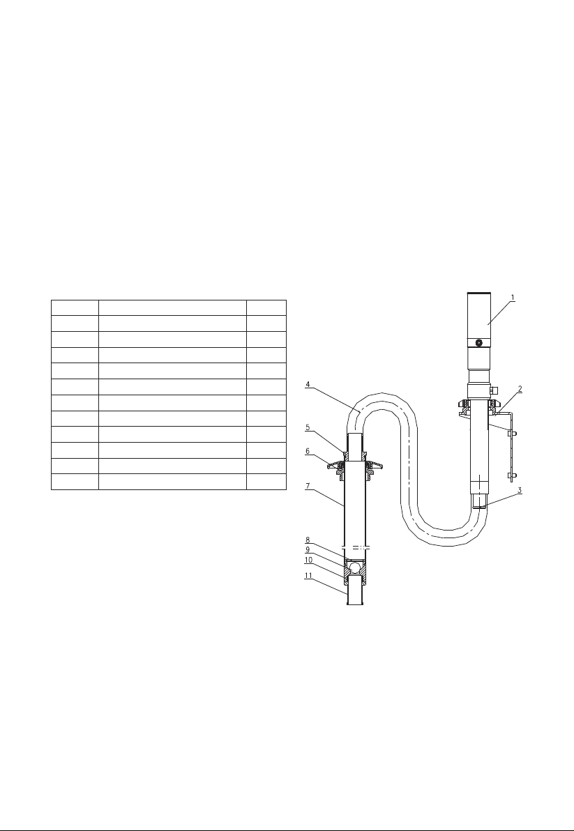
Damage to Screw (5) or plate (8)
Insufficient oil supply
Damage to Piston (7) or gasket (9)
or spring (10)
Insufficient oil supply
O-ring (3) Seal (17) (29) (31) (37)
damage
Tube (41) damage
Piston (7) wear
O-ring (3) Seal (17) (29) (31) (37)
damage
A blockage in a hose, valve
Slincer dirty or damage
1. Increase air pressure
2. Clear air passage
3. Change voltage
1. Open the intake valve
2. Clean the intake valve
Pressure release, cleaning device
Assess damage, repair or replace
Screw (5) or plate (8)
Replace oil drums to ensure
adequate oil supply
Assess damage, repair or replace
Piston (7) or gasket(9) or spring (10)
Replace oil drums to ensure
adequate oil supply
Change Corresponding O-ring or
seal
Change tube (41)
Change piston (7)
O-ring (3) Seal (17) (29) (31) (37)
damage
Pressure release, cleaning element
Substitute damaged elements

E8
HOW TO USE
Directly Fitted Pump into the Drum
1. Insert the suction tube of pump into the drum and secure with ring nut, suitable for
commercial drums with 57mm diameter hole and threading 2” BSP
2. Fit a oil delivery tube for oil outlet of the air operated pump using only high quality tubes
(normally 1/2”, according to DIN-SAE norms(), by means of 1/2” BSP threading fitting.
3. Oil delivery pistol: Connect delivery tube with delivery pistol using suitable pipe fittings, and
point the pistol at right place.
4. Air inlet connection is 1/4” quick plug ( or 1/4” NPT female) in all versions. Compressed air
connection ( to be supplied by the customer) should be done using suitable tube.
5. A pressure regulator to keep the pump’s working pressure at the best possible level (max
5-10 bar) between the pump and the compressed air line
6. A cut-off switch can enable the operator to stop the pump at any given moment by cutting
the air supply off between the pump and the compressed air line
7. Switch on all switch.
WALL INSTALLED
Part List
Proceed As Follows
1. Secure the bracket to the wall using the dowels at about 1200mm height appropriate for the
tank’s dimensions. Make sure that the wall is solid and thick enough for the dowels. Do not
interfere with hydraulic tubes or electric lines.
2. Secure the pump to the bracket 2
3. Connect the flexible suction tube 4 to the pump using the clamp provided.
4. Connect the rigid suction 7 to the end of the flexible suction tube 4 using the elastic clamp
provided
5. Put the bung adapter 6 into the drum hole.
6. Put the rigid suction tube 7 into the pump and secure it in place
QTY
1
1
1
1
1
1
1
1
1
1
1
Description
Oil pump
Wall bracket
Pump adapter
Flexible suction hose
Suction hose adapter
Bung adapter
Rigid suction tube
Spring circlip
Ball
Valve seat
Filter
Part No.
1
2
3
4
5
6
7
8
9
10
11

E9
Extension Transfer
Part List
Proceed as follows
1. Depending on the length of the suction tube the desired extension length. Can be realized by
using the modular extension elements (See the examples given above)
2. Example of possible application to pump with drum or rigid suction tube for obtaining
personalized lengths according to needs.
3. Remove filter and foot valve from the stub pump, screw the extension tube on (W/top
connection), then screw filter and foot valve on the extension tube (foot connection end!)
Connect the Pump with Other Accessories:
Part List
QTY
1
1
1
1
1
1
1
1
1
Description
Oil pump
Bung adapter
Top connection
Extension 500mm tube
Extension sleeve
Extension 200mm tube
Foot connection
Foot valve
Filter
Part No.
1
2
3-1
3-2
3-3
3-4
3-5
4
5
Description
Oil pump
Bung adapter
Oil pistol
Hose with fitting
Air hose with quick coupling
Drum
Filter, pressure regulator
and lubricator
Part No.
1
2
3
4
5
6
7(7-1, 7-2, 7-3)
1
3
4
5 7
2
6

E10
EXPLODED AND PARTS LIST
46
1
2
3
4
5
6
7
8
9
10
11
12
13
1414
15
16
17
18
3
1920
21
22 2323
24
25
26
27
31
28
29
30
33
34
35
36
37
38
39
40
41
42
43
44
45
(46)
32

E11
Q’ty
1
1
2
1
3
1
1
1
1
1
1
1
1
2
1
1
1
1
1
1
1
1
2
1
Description
Air motor cover
Spring
O-ring
Tube
Cross screw
Retainer plate
Piston
Base
Washer
Spring
Spring
Plate
Piston
O-ring
Shaft
Pin
Lip Seal
Guide belt
Air control center
Connector
Silencer
Quck plug
O-ring
Silencer
Part No.
25
26
27
28
*29
30
*31
32
33
34
35
36
*37
38
39
40
41
*42
43
44
45
46
(46)
Description
Circlip - Type A
Oil inlet
Washer
Guide belt
Piston sealing
Base
O-ring
Circlip - Type A
Shaft
Connector
Elastic pin
Bearing ball
Piston sealing
Piston
Guide belt
Locking sleeve
Tube
O-ring
Spring
Bearing ball
Valve seat
Connector
Filter assembly
Q’ty
1
1
1
1
1
1
1
1
1
1
1
1
1
1
1
1
1
1
1
1
1
1
1
Part No.
1
2
*3
4
5
6
*7
8
9
10
11
12
13
*14
15
16
*17
18
19
20
21
22
*23
24
Note: The Part No. with “*” are the wearing parts.

E12
TECHNICAL DETAILS - OIL CONTROL VALVE
SAFETY PRECAUTIONS
EQUIPMENT MISUSE HAZARD
1. This equipment is for professional use only.
2. Read all instruction manuals, tags, and labels before operating the equipment.
3. Use the equipment only for its intended purpose. If you are not sure, call your distributor.
4. Do not alter or modify this equipment.
5. Check equipment daily. Repair or replace worn or damaged parts immediately.
6. Do not exceed the maximum working pressure of the lowest rated system component. This
equipment has a 1500psi (10Mpa,100bar) maximum working pressure.
7. Use fluids and solvents which are compatible with the equipment wetted parts. Refer to the
Technical Data section of all equipment manuals. Read the fluid and solvent manufacturer’s
warnings.
8. Route hose away from traffic areas, sharp edges, moving parts, and hot surfaces.
9. Do not lift pressurized equipment.
10. Comply with all application local, state, and national fire, electrical, and safety regulations.
INJECTION HAZARD
Spray from the valve, leaks or ruptured components can inject fluid into your body and cause
extremely serious injury, including the need for amputation. Fluid splashed in the eyes or on
the skin can also cause serious injury.
1. Fluid injected into the skin might look like just a cut, but it is a serious injury. Get immediate
medical attention.
2. Do not point the valve at anyone or at any part of the body.
3. Do not put your hand or fingers over the grease fitting coupler.
4. Do not stop or deflect leaks with your hand, body, glove or rag.
5. Tighten all fluid connections before operating the equipment.
6. Check the hose, tubes, and couplings daily. Replace worn or damaged parts immediately.
Do not repair high pressure couplings; you must replace the entire hose.
INSTALLATION
Typical Installation
Fig. 1 shows a typical installation.
The installation shown in Fig. 1 is only a guide. The components shown are typical; however, it
is not a complete system design. Contact your distributor for assistance in designing a system
to suit your particular needs.
Pre-Installation Procedure
1. Relieve the pressure.
To reduce the risk of serious injury whenever you are instructed to relieve pressure, always
follow the pressure relief procedure.
2. Close the fluid shut-off valve (Item 4 in Fig.1).
3. Ground the hose and reel or console. Do not use PTFE tape on the pipe joints; it may cause
a loss of ground across the pipe joint.
Item No.
Inlet
Configure
Flow Rate
Operating Pressure Range
Max Operation Temperature
Accuracy
Battery
18123522
1/2" NPT Female
Flexible nozzle, auto tip
0.3-9GPM
7-1500psi
140°F
±0.5%
ER14250 3.6V

E13
Installation Procedure
If this is a new installation, or if the oil in the lines is contaminated, flush the lines before you
install the dispense valve.
1: Air inlet
2: Air shut-off valve
3: Oil pump
4: Fluid shut-off valve
5: Meter
6: Control valve
7: Hose reel
NEW INSTALLATION
1. Relieve the pressure.
To reduce the risk of serious injury whenever you are instructed to relieve pressure, always
follow the pressure relief procedure.
2. Close the fluid shut-off valve at each dispense position.
3. Make sure the main fluid outlet valve at the pump is closed, the air pressure to the pump
motor is adjusted, and the air valve is open. Slowly open main fluid valve.
4. Place the hose end (with no dispense valve connected) into a container for waste oil. Secure
the hose in the container so it will not come out during flushing. If you have multiple dispense
positions, first flush the dispense position farthest from the pump, and work your way toward
the pump.
5. Slowly open the shut-off valve at the dispense position. Flush out a sufficient amount of oil to
ensure that the entire system is clean, and close the valve.
6. Repeat step 5 at all other dispense positions.
1: Trigger
2: Nozzle
3: Tip
4: Swivel nut
Remark: If you want to adjust the angle of the nozzle, you can loosen the #4 swivel nut, then
turn the nozzle to your desired position and tighten the nut.
Existing Installation
1. Relieve the pressure:
To reduce the risk of serious injury whenever you are instructed to relieve pressure, always
follow the pressure relief procedure.
2. Loosen and disconnect the hose from the old dispense valve (the one that you are replacing).
3. Thread the extension into the outlet of the dispense valve, and tighten firmly.
NOTE: Do not over tighten the extension tube assembly by using the nozzle adapter to hand
turn the nozzle. For rigid extensions, thread the extension in at least three full turns, position
the extension for proper alignment, and tighten the sealing nut. The PTFE seal on the
sealing nut must face the valve housing.
2
1
3
4
5
6
7
Fig. 1
2
1
3
4
Fig. 2

E14
4. Apply thread sealant to the male threads of the hose fitting, thread the hose fitting into the
swivel, and tighten firmly.
5. Thread the new nozzle or nozzle adapter onto the extension, and tighten firmly.
6. Open all dispense position shut-off valves, and start the pump to pressurize the system. See
the Operation section for proper operation.
7. For metered dispense valves, to ensure dispensing accuracy, purge all air from the fluid
lines and dispense valves before you use them.
Grounding
Proper grounding is an essential part of maintaining a safe system.
To reduce the risk of static sparking, ground all system components per local and national
electrical codes.
Refer to the user manuals for the pump and other system components to ground the following:
1. Pump: Follow manufacture’s recommendations.
2. Air and Fluid hoses: Use only grounded hoses.
3. Air compressor: Follow manufacture’s recommendations.
4. Fluid supply container: Follow your local code.
5. To maintain grounding continuity when flushing or relieving pressure, always hold a metal
part of the valve firmly to the side of a grounded metal pail, then trigger the valve.
OPERATION
CAUTION:
1. Never operate the meter with the plastic cover removed. The cover protects the meter from
damage due to impact. Meters are factory sealed to keep moisture and dirt out.
2. To prevent line contamination, which can cause equipment malfunction or damaged, flush
the lines before you install this equipment in the system.
Display and Button Usage
To Activate the Digital Display
1. Press the RESET key pad to clear the meter before starting a new dispense cycle. This is the
best way to activate the meter, because it also clears the quantity of the last dispense cycle.
2. The digital display can also be activated by pressing the MENU key pad or by running fluid
through the meter.
Calibrating Automatically
1. Press Reset key for 1 second and Area 1 shows .000 L;
2. Keep running fluid through the meter until the fluid running out of the certain measuring
cylinder. The display will show certain value as *.**L, press the Menu key for 3 seconds. The
meter will enter instrument calibration mode and Area 1 shows 00*.**L;
3. Press Menu key to move the flashing digital, press Reset key to choose number, enter the
fluid volume and press Menu key again for 3 seconds, then exit the calibration mode. The
calibration settled.
AREA 1: FOR LAST DISPENSE CYCLE AREA 2: FOR MEASUREMENT UNITS
AREA 3: FOR ACCUMULATED
TOTAL
AREA 4: FOR BATTERY
CAPACITY
Notes: It will flashing when
battery voltage less than 3.3V;
Menu: MOVING THE NUMBERS FOR
ADJUSTING THE CALIBRATION AND
CHOOSING THE UNITS
Reset: CHOOSING THE UNITS AND SETTING
CORRECTION FACTOR

Show Current Correction Factor
Press Menu key and Reset key together. The display will show the correction factor, which can
be reset.
Reset The Resettlement Total
Press Menu key for 10 seconds, the accumulated total will be reset to be “0”.
To Change the Measurement Units (L / GAL/ PT / QT meter only)
1. Move the flashing display to Area 2 by pressing Menu key, then press Menu key to choose
measurement unit;
2. Press Menu key over 3 seconds to exit the setting mode.
CAUTION:
1. To be sure the proper amount of fluid is dispensed, always use the same measurement unit
for a particular fluid. Units should be changed only by authorized employees.
2. To Verify the Accuracy of an Digital Meter.
3. Use a clean, calibrated container. If using a single container, be sure to clean it after each
dispense.
4. Have pump air pressure at the lowest possible setting for dispensing fluid.
5. Put the tip of the nozzle at the bottom of the calibrated container.
6. If the tip of the dispense valve does not reach the bottom of the calibrated container, use a
length of plastic tubing over the tip of the nozzle to ensure liquid enters the container from
the bottom.
7. Trigger the gun slowly so the fluid immediately covers the tip of the dispense valve.
Pressure Relief Procedure
Pressurized Equipment Hazard:
The equipment stays pressurized Fluid under high pressure can be injected through the skin
and cause serious injury. To reduce the risk of an injury from injection, splashing fluid, or
moving parts, follow the pressure relief procedure whenever you:
1. Are instructed to relieve pressure.
2. Check, clean or service any of the system equipment.
3. Install or clean the nozzle.
1. Turn off the power supply to the pump.
2. Trigger the valve into a waste container to relieve pressure.
3. Open any bleed-type master air valves and fluid drain valves in the system.
4. Leave the drain valve open until you are ready to pressurize the system.
If you suspect that the dispensing valve, extension, or nozzle is clogged or that
pressure has not been fully relieved after following the steps above, very slowly loosen
a fitting on the fluid line to relieve pressure gradually, then loosen it completely, then
clear the clog.
To reduce the risk of a serious bodily injury, including fluid injection, never exceed the
maximum working pressure of the valve you are using or of the lowest rated component
in your system.
Dispensing Procedure
Note: Before you begin, make sure you understand how to unlock the trigger.
1. Pull the trigger toward the valve body to open the valve and begin dispensing.
2. Lock the valve open by keeping the trigger squeezed and depressing the trigger lock button.
Then release the trigger, releasing your forefinger from the trigger lock last.
3. Pull the trigger toward the valve body to release the trigger lock. The trigger lock disengag-
es. Release the trigger to stop dispensing.
E15

E16
TROUBLE SHOOTING GUIDE
Relieve the pressure before you check or repair the dispensing valve. Be sure all other valves
and controls and the pump are operating properly.
To reduce the risk of serious injury whenever you are instructed to relieve pressure, always
follow the pressure relief procedure.
Problem
Slow or no fluid flow.
Oil leaks from swivel.
Oil drips from nozzle.
Valve leaks.
Leakage from meter.
No Display.
Wrong Reading.
Problem
Filter is clogged, or pump pressure is low,
or shut-off valve is not fully open, or
foreign materialis jammed in the
metering element.
Swivel is loose.
O-ring is worn or damaged.
Nozzle is damaged or obstructed.
O-rings or valve seat are worn or damaged.
O-ring damaged.
Loosing Battery.
Battery out of power.
correction coefficient error.
Solution
1. Relief the pressure.
2. Loose swivel fitting, clean or replace the filter.
3. If the problem remains, contact your
distributor for repair or replacement.
Torque the swivel.
If the problem remains, contact your distributor
for repair or replacement.
Replace the o-ring.
If the problem remains, contact your distributor
for repair or replacement.
Inspect the nozzle for damage or obstructions,
and replace if damaged.
If the problem remains, contact your distributor
for repair or replacement.
Replace the o-rings and/or the valve seat.
If the problem remains, contact your distributor
for repair or replacement.
1. Get the meter off from the dispense system.
2. Take off the protector.
3. Loosing four the socket head cap screws on
the cover of the meter.
4. Loosing eight the hex bolts on the bottom of
the meter.
5. Take off the seat.
6. Check the o-ring, replacing the o-ring if it is
damaged.
7. After replacing the o-ring, assemble the meter
and fix it back to the dispense system.
1. Get the meter off from the dispense system.
2. Take off the protector.
3. Take off the labels sticks on the bottom of the
meter.
4. Loosing the five socket head cap screws on
the bottom of the meter.
5. Take off the seat.
6. Check the battery, replacing the battery if it is
out of power.
7. After replacing the battery, assemble the
meter and fix it back to the dispense system.
Reset the correction factor (follow the
instructions on Page 6).

E17
EXPLODED AND PARTS LIST
4
3-5
3-3
3-9
3-18
3-21
3-12
3-17
3-2
3-20
3-15
3-19
3-11
3-14
3-10
3-1
3-16
3-13
3-4
3-6
3-8
3-7
1-9
1-1
1-13
1-12
1-11
1-10
1-3
1-7
1-5
1-8
1-4
1-2
1-6
Part No.
1-1
1-2
1-3
1-4
1-5*
1-6
1-7
1-8
1-9*
1-10
1-11
1-12
1-13*
2
3-1*
3-2
3-3
3-4
Description
Swivel
handle
trigger lock
Trigger
O-ring
Screw
Rod
Cam
Seat
Spring
Seat
Spring
Filter
Adapter
O-ring
Meter Holder
Meter Cover
Rubber Protector
Q’ty
1
1
1
1
2
2
1
1
1
1
1
1
1
1
1
1
1
1
Part No.
3-5
3-6
3-7
3-8
3-9*
3-10
3-11
3-12
3-13*
3-14
3-15
3-16
3-17
3-18
3-19*
3-20*
3-21
4
Description
Main Circuit Board
Front Label
Screw
Screw
O-ring
Seat
Battery cover
Spring
Battery
Screw
Shaft
Oval Gear
Magnetic Rod
Bolt
Waterproof protector
Seal washer
Washer
Flexible nozzle with tip
Q’ty
1
1
4
4
1
1
11
1
1
2
2
2
2
8
2
4
4
1
Part No.
3-9*
3-13*
3-19*
3-20*
Description
O-ring
Battery
waterproof protector
Seal washer
Q’ty
1
1
1
4
Wearing parts:
This manual suits for next models
1
Table of contents
Other Macnaught Dispenser manuals