Stocks AG ROTOR METER Vari Speed 65 User manual

Original Instructions, Revision 1 August 2020
ROTOR METER 65 & 130
Vari Speed
Original Operating Manual and parts list
Read carefully before installation and
operation
This document must not be copied duplicated or distributed without prior consent .
All and patent rights apply
STOCKS AG LIMITED, CROMWELL ROAD, WISBECH, CAMBRIDGESHIRE, UK.

2
Index 2020
Section Page No.
2 Index 2
3-1 General information 3
3-2 Technical data 3
3-3 Intended use 3
3-4 Unintended use 3
4 Contents of the EC Declaration of Conformity 4
5 Contents of the UKCA Declaration of Conformity 5
6-1 Machine identification 6
6-2 Warranty 6
7 Safety 7
8-1 Emergency Stop Instructions 8
8-2 Maintenance 8
9 Safety warning decals and safety signs 9
10-1 Clearing a blockage 10
10-2 Hopper Removal 10
10-3 Storage 10
10-4 OPTIONAL Heavy Duty Waterproof Cover 10
10-5 Disposal 10
11 Machine Mounting 11
12-1 Electrical Components 12
12.2 Electrical Connections 12
13 Control Boxes 13
14-1 Setting the feed rate 14
14-2 Feed roller configuration 14
14-3 Changing the feed rollers 14
15 5mm feed roller combinations 15
16 8 section feed roller combinations 16
17-1 Product Calibration 17
17-2 Calibration catch and weigh test 17
18 Parts drawing 18
19 Parts list (page 1) 19
20 Parts list (page 2) 20

3
3-1 General information
Congratulations on your Rotor Metre purchase;
Please check the machine for any transport damage upon receipt and advise your supplier
of any problems immediately. Late claims regarding any damage may be rejected.
IMPORTANT
This Operating Manual forms part of the machine and must be readily available for the operator
who must read and follow the points covered before use
3-2 Technical data
Model: Rotor Meter (Gravity Fed)
65 litre machines: Net weight: 35kg Dimensions (W x D x H) 50 x 53 x 103cm (boxed 51 x 58 x 94cm)
130 litre machines: Net weight: 40kg Dimensions (W x D x H) 61 x 60 x 123cm (boxed 62 x 62 x 114cm)
Operating Voltage 12v; Power requirement 5 amps Motor outputs: 60W
Noise level: 60dB
Model: Rotor Meter (Air Fed)
65 litre machines: Net weight: 38kg Dimensions (W x D x H) 50 x 53 x 103cm (boxed 51 x 58 x 94cm)
130 litre machines: Net weight: 43kg Dimensions (W x D x H) 61 x 60 x 123cm (boxed 62 x 62 x 114cm)
Operating Voltage 12v; Power requirement 15 amps Motor outputs: 180W
Noise level: 85dB
3-3 Intended use
This machine has been designed to safely apply small seeds and granular products in the agricultural,
horticultural and amenity sector for mounting onto various parent implements such as power harrows, seed
drills, planters, and vineyard interrow equipment.
The operator alone bears the associated risk if used for unintended use.
Intended use also includes compliance with the conditions for operation, maintenance, and repairs.
The implement may only be used, maintained and repaired by persons who have relevant experience and
aware of the risks involved.
The manufacturer is not liable for any resulting damage if the machine is used for any other purpose than
the intended use also includes compliance with the conditions for operation, maintenance, and repairs pre-
scribed within this instruction manual .
This machine should not be used in the rain or during a thunderstorm.
The applicable accident prevention regulations as well as the other generally safety-related, occupational
health and road traffic regulations must also be observed.
Specifications descriptions and illustrations in this manual are accurate at the time of this publication but
may be subject to change this manual are correct at the time of printing but we reserve the right to change
and improve them. This machine is designed with safety in mind.
Maintenance and servicing in accordance with this manual will ensure safe operation and reliability of your
machine for many years
3-4 Unintended use
This machine is not designed to apply abrasive materials such as sand & grit or for applying salt products

4
E.C. DECLARATION OF CONFORMITY
Machine Type: Mounted Agricultural Implement - Pellet and Seed application broadcasters
Model(s): Fan Jet Pro All Variants & Versions
Fan Jet Pro Plus All Variants & Versions
Fan Jet Twin All Variants & Versions
Fan Jet Mini All Variants & Versions
Fan Jet Duo All Variants & Versions
Turbo Jet All Variants & Versions
Rotor Meter All Variants & Versions
Rotor Meter Air Force All Variants & Versions
Micro Meter All Variants & Versions
Maxi Meter All Variants & Versions
Serial No. ……………………………………………………………………………………………
Manufacturer: Stocks Ag Ltd
Cromwell Road
Wisbech
Cambridgeshire PE14 OSD
United Kingdom
This is to declare that the above machine conforms to the relevant Essential Health and Safety Requirements of the
Machinery Directive 2006/42/EC, implemented in the United Kingdom by Statutory Instrument 2008 No.
1597 – The Supply of Machinery (Safety) Regulations 2008 as amended.
The following standards have been applied in the design and construction of this machine:
BS EN ISO 12100: 2010 Safety of machinery – Basic concepts, general principles for design – Basic
terminology, methodology.
BS EN ISO 4254-1: 2015 Agricultural machinery – Safety - General requirements
BS EN ISO 4254-8: 2018 Agricultural machinery – Safety – Solid fertilizer distributors.
BS EN ISO 13854: 2019 Safety of machinery – Minimum gaps to avoid crushing of parts of the
human body.
BS EN ISO 13857: 2019 Safety of machinery – Safety distances to prevent hazard zones
aaaaaaaaaaaaaaaaaaaaaaaaaaaaaaaaaabeing reached by the upper and lower limbs.
The manufacturer stated above holds the technical file for this machine.
Signed on behalf of Stocks Ag Ltd
Name: J Woolway
Date: 06th August 2020
Position: Managing Director
t. +44 (0) 1945 464909 f. +44 (0) 1945 464985 e. sales@stocks-ag.co.uk

5
UKCA. DECLARATION OF CONFORMITY
Machine Type: Mounted Agricultural Implement - Pellet and Seed application broadcasters
Model(s): Fan Jet Pro All Variants & Versions
Fan Jet Pro Plus All Variants & Versions
Fan Jet Twin All Variants & Versions
Fan Jet Mini All Variants & Versions
Fan Jet Duo All Variants & Versions
Turbo Jet All Variants & Versions
Rotor Meter All Variants & Versions
Rotor Meter Air Force All Variants & Versions
Micro Meter All Variants & Versions
Maxi Meter All Variants & Versions
Serial No. ……………………………………………………………………………………………
Manufacturer: Stocks Ag Ltd
Cromwell Road
Wisbech
Cambridgeshire PE14 OSD
United Kingdom
This is to declare that the above machine conforms to the relevant Essential Health and Safety Requirements of the
Machinery Directive 2006/42/EC, implemented in the United Kingdom by Statutory Instrument 2008 No.
1597 – The Supply of Machinery (Safety) Regulations 2008 as amended.
The following standards have been applied in the design and construction of this machine:
BS EN ISO 12100: 2010 Safety of machinery – Basic concepts, general principles for design – Basic
terminology, methodology.
BS EN ISO 4254-1: 2015 Agricultural machinery – Safety - General requirements
BS EN ISO 4254-8: 2018 Agricultural machinery – Safety – Solid fertilizer distributors.
BS EN ISO 13854: 2019 Safety of machinery – Minimum gaps to avoid crushing of parts of the
human body.
BS EN ISO 13857: 2019 Safety of machinery – Safety distances to prevent hazard zones
aaaaaaaaaaaaaaaaaaaaaaaaaaaaaaaaaabeing reached by the upper and lower limbs.
The manufacturer stated above holds the technical file for this machine.
Signed on behalf of Stocks Ag Ltd
Name: J Woolway
Date: 01st December 2020
Position: Managing Director
t. +44 (0) 1945 464909 f. +44 (0) 1945 464985 e. sales@stocks-ag.co.uk

6
6-1 Machine identification
The machine the serial number decals are mounted on the steel chassis to one side of the hopper
6-2 Warranty
We provide a 12 month warranty as of the date of invoice
(your invoice for the machine which will serve as a warranty certificate).
This warranty is applicable for cases of material or construction faults and does not include parts that are
damaged by normal or excessive wear.
Warranty expires if damage is caused by external forces, operator error, modifications, Jet washed or if
the machine has not been used for its intended use.
Contact the company whom you purchased the machine from in the event of any problems, or before at-
tempting any repair. If the base machine or the controls system are modified in any way this will void any
warranty claim.
Please see our conditions of sale for full details a copy of which available upon request
Please record the machine serial number here; S/N ……………………………….
Purchase date: ………………………………… Dealer ……………………………...
ROTOR METER
MK2MODEL
SERIAL No 217200
MANUFACTURED 2021
BY:-
STOCKS AG LIMITED
CROMWELL ROAD
WISBECH, CAMBS.
PE14 OSD, UK

7
7 Safety
Ensure care is taken when lifting the machine
Safe lifting practice to be observed when handling as the net weight is over 25kg
We advise safety shoes and protective gloves are worn when handling the machine
Assistance will be required when lifting or lowering the machine
Care to be taken to avoid crushing due to the weight of the machine.
When lifting or fitting the machine to the parent vehicle or implement ensure work is performed on level
ground or flat surface to avoid slipping, stumbling or falling.
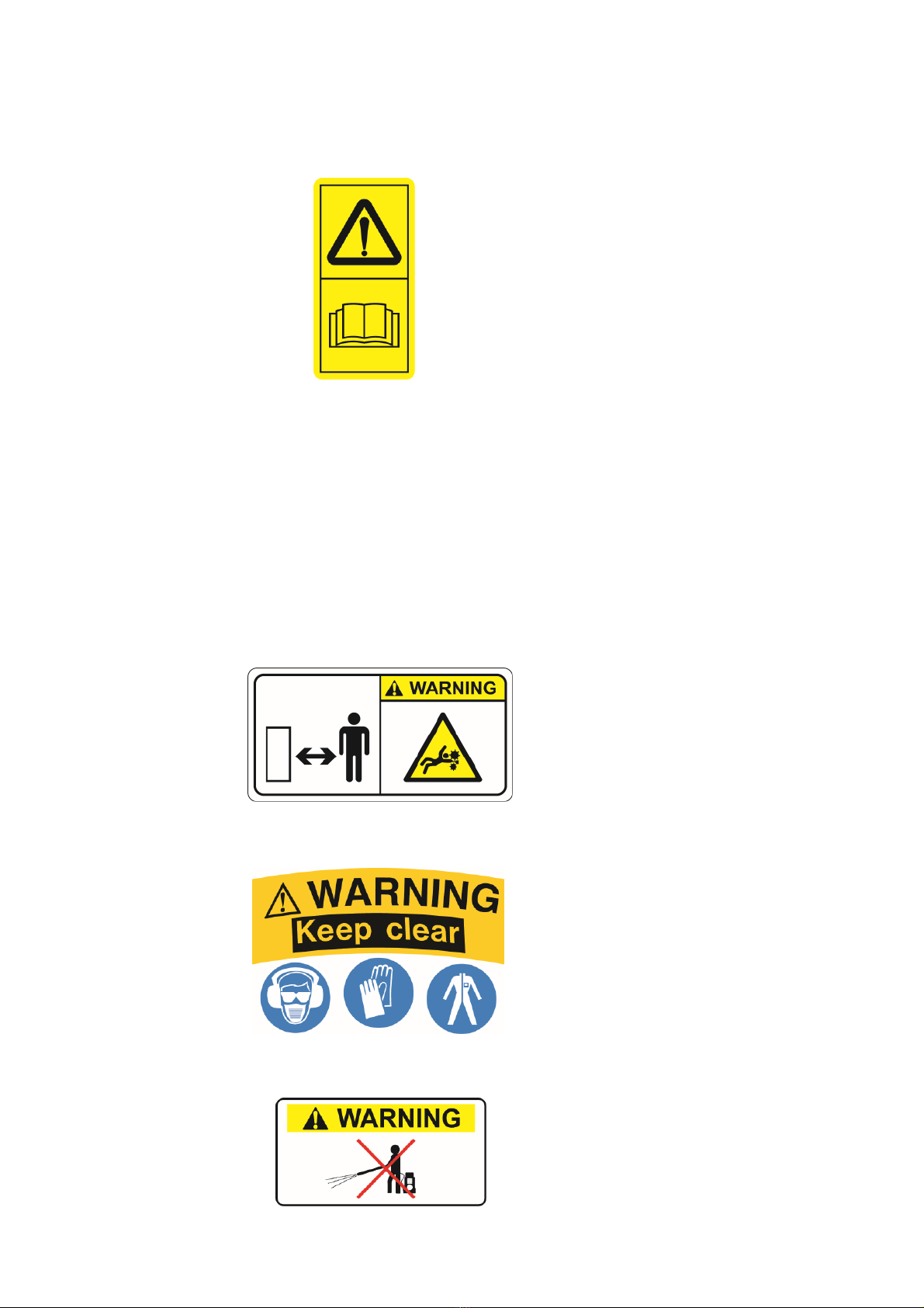
PERSONAL PROTECTION EQUIPMENT It is the responsibility of the operator or maintenance
engineer to ensure safe handling of the machine and the appropriate personal protection
equipment is worn for the material being applied and to prevent contamination to the machine or
the environment.
WARNING Always observe all application standards and guidelines provided by the product
manufacturer as some seed dressings and granular products may be toxic !
NOTE if unsure contact your seed or product supplier for more information.
If applying slug pellets or other toxic material and the parent vehicle has a closed cab the operator must
ensure the cabin is always closed and the air filter system is in good order.
Always ensure the stability of the parent vehicle is not affected when the machine is in use.
If in doubt contact the vehicle manufacturer for more information.
After working the machine ensure that any unused product is returned safely to its original packaging
Stocks AG Ltd. does not accept any liability for the storage and use of the material being applied
If unsure contact the material supplier for more information.
WARNING Always adhere to the warning information and do not
remove any guard whilst the machine is in operation .
The machine may only be used, maintained and repaired by persons who have relevant
experience or a machinery dealer who is aware of any risks involved.
The applicable accident prevention regulations as well as the other generally safety related, occupational
health and road traffic regulations must also be observed.
The manufacturer is not liable for any damage resulting from unauthorised modifications and the use of
components and auxiliary parts
The machine must be checked regularly by the operator (before each use) for any damage loose bolts or
electrical connections, vibrations, unusual sounds, and to ensure they function correctly.
The machine must not be operated in wet weather conditions or during thunderstorms.
Observe the generally applicable safety and accident prevention regulations
Always empty the hopper of toxic materials to prevent harm to humans and animals after each use and prior to
storage.
WARNING
Always isolate the power supply if servicing or leaving the machine unattended.

8
8-1 Emergency Stop instructions
1. Power down the control system immediately by switching the main power switch on the left hand
side of the cab control panel to the upper position A
2. Disconnect the power supply by unplugging the power cable or removing the inline fuse.
8-2 Maintenance
WARNING
Always ensure the power supply is disconnected before any
maintenance work or cleaning of this machine.
Suitable protective clothing must be worn (See page 6)
DO NOT JET WASH THIS MACHINE
The machine must be checked regularly by the operator for any damage loose bolts or electrical connections,
vibrations, unusual sounds, and to ensure they function correctly.
Before use;
1. Ensure the machine is securely mounted
2. Check the power supply
3. Ensure all feed outlets, air chamber (Air Force machines) and all feed hoses are clear of any product
4. Check the feed block is configured correctly and free running before starting work
Daily checks;
1. Check the feed motor and 12v Fan (Air Force machines) are working correctly
2. Ensure feed outlets and air chamber (Air Force machines) and all hoses are clear of product
After each use;
1. Empty hopper before removing the feed block assembly and clean the machine thoroughly ensuring all
product residue has been cleaned from the hopper feed rollers and body of the machine.
2. Store in dry conditions to protect the machine and control system from moisture
WARNING Always observe all guidelines provided by the product manufacturer with regards to
handling storage and disposal of products as some may be toxic !
A
A
Vari Speed Control Panel AirForce Control Panel
A
A

9
9 Safety Warning Decals
Important ; observe this safely decals on the machine
WARNING
Read and understand the Operators Manual
instructions before operating this machine
Operator errors can result in serious injury
WARNING
Do Not Jet Wash
This machine is not designed to
withstand Jet Washing !
WARNING
Danger moving parts
Risk of serious injury whilst the machine is
in operation
WARNING
Risk of injury
Keep a safe distance whilst the
machine is in operation
WARNING
Keep Clear
Maintain a safe distance from the machine
when in operation
Wear the appropriate protective personal
equipment

10
10-1 Clearing a blockage
Disconnect the main power supply
Ensure the parent machine is stationary, switched off, and parked on level ground
Ensure the main power switch on the control panel is off and unplug the power supply cable or disconnecting
the power cable from the vehicle battery.
Ensure appropriate personal protection equipment is worn for the product being applied
Ensure any product removed is put back into its original container
Care to be taken not to spill any product that could contamination the environment.
Empty the hopper of any remaining product
10-2 Hopper removal
Removing the hopper for cleaning and maintenance
Ensure the hopper is completely empty and free from any product residue Ensure appropriate personal
protection equipment is worn for the product being applied
Release the rubber lid retaining straps and remove the lid. The
hopper can then be lifted away after removing the retaining plate
(s) from within the hopper by releasing the M8 external fixing nuts
and washers.
NOTE When replacing he hopper ensure the Gasket fitted under
the base of the hoper is in good order
Replace if damaged; part number FJ017S
10-3 Storage
Disconnect the power supply by unplugging the power cable or
removing the inline fuse from the power cable if storing the
machine for long periods.
It is the responsibility of the operator to ensure the hopper is empty after each and use and cleaned
thoroughly before storage.
Store in dry conditions to protect the machine and control system from moisture
Always clean and spray electrical connectors with a moisture repellent spray when not in use for long periods.
10-4 Optional PVC Waterproof Covers
Heavy duty White PVC covers fitted with eyelets and bungie cord for easy attachment available for all
machines. Available through your local dealer
To order a 65L Waterproof PVC Covers quote part number LC65
To order a 130L Waterproof PVC Covers quote part number LC130
10 - 5 Disposal
Ensure that any persons handling the machine are aware that the machine may have been used to
apply toxic chemicals and so the appropriate personal protection equipment should be worn.
Ensure the hopper contents have been removed and any toxic residue removed and put back into a sealed
contained or disposed of in accordance with the manufacturers guidelines to eliminate any possible
contamination of others or the environment
Always adhere to the local disposal regulations paying particular attention to the plastics, rubber,
and electrical components.

11
Mount the machine using the Base Plate.
This has 4 holes in the base to take M12 bolts (see below) use these to attach to the parent vehicle and is
attached to the chassis by 2 bolts and spacers which act as the pivot, and a removable steel pin secured by an
‘R’ clip.
Gravity fed machines; mount the base plate at the rear of the machines to allow room for feed hose
Air fed machines; the base plate can be base or rear mount
Ensure there is sufficient room to tip the hopper for emptying and ensure any potential trapping
points are noted taking care not to trap hands or fingers
NOTE feed hoses will need to be removed before tipping the hopper
The machine must be on level ground or flat surface before tipping the hopper to avoid the hopper
accidently tipping forward once the tipping pin has been removed.
To tip the hopper, remove the pin whilst supporting the hopper, lower gently when emptying the hopper.
11-1 65L and 130L Machine Mounting
Base
Mounting
Rear
Mounting
200mm
150mm

12
12 -2 Electrical Connections
Power requirement is 12 volts with a minimum continuous 15 amp supply for a gravity fed machine or 30amps
for an Air Force machine
The machine is supplied with a control console and all wiring
Ensure the power supply cable (2) is connected direct to the vehicle battery to ensure maximum power.
Connect the positive wire (fused) to the positive (+) terminal and negative earth connection to the negative (-)
terminal.
Control extension cables available (please enquire)
WARNING Failure to connect to the vehicle battery may result in control function problems and possible dam-
age to the vehicle battery and charging system must be in good condition to achieve the best results.
All cables and controls are fitted with matching plugs and sockets.
WARNING any modification to the wiring, fuse holder or controls will invalidate any warranty claim
and may affect the performance of the machine.
Always replace any blown fuse with the same amp rated blade type fuse as the original one fitted.
12 -1 Electrical Components
Vari Speed machine components
1. GA115B Control Panel
2. MM107B 5m Fused Power Cable
3. MM108B 6m Control Connector Cable
4. MM044B Feed Motor
Air Force machine components
1. FJ110D Control Panel
2. FJ107F 7m Fused Power Cable
3. FJ108D 6m Control Connector Cable
4. FJ109D Tail Piece
5. FJ055A Toggle Switch
6. TJ120 12v Fan Unit
7. MM044B Feed Motor
12
5 4
6
7
3
1
2
34

VARI SPEED CONTROL
This is a simple and effective low cost manually operated electric control used to instantly start and stop the
feed motor at headlands, and uses a dial control to set the feed motor speed and thus the application rate. It
is not linked to forward speed so once calibrated the operator drives at a consistent forward speed to maintain
the rate, or can manually increase or decrease application rates on the move using the dial.
The left hand toggle switch (A) is Power On / Off and starts and stops the feed motor.
The motor is 2 speed and is switched using the centre toggle switch (B) from Low to High.
A 12 position rotary dial (C) offers 12 different speeds in each range, providing a total of 24 different motor
speeds. Application rates are increased with higher motor speeds and decreased with lower motor speeds.
AIR FORCE CONTROL
This is a simple and effective low cost manually operated electric control used to instantly start and stop the
feed motor at headlands, and uses a dial control to set the feed motor speed and thus the application rate. It
is not linked to forward speed so once calibrated the operator drives at a consistent forward speed to maintain
the rate, or can manually increase or decrease application rates on the move using the dial.
The left hand toggle switch (A) is Power On / Off and starts and stops the fan motor. The fan motor is con-
trolled using the left hand 12 position rotary dial (B) offering 12 different speeds.
The right hand toggle switch (C) is the feed motor control and starts and stops the feed motor.
The right hand rotary dial (D) adjust the motor speed. The feed motor is 2 speed, and the 2 speed toggle
switch is located on the feed motor splash guard marked HIGH / LOW . Select motor speed as required, and
the 12 position rotary dial gives 12 different speeds in each range, providing a total of 24 different motor
speeds. Application rates are increased with higher motor speeds and decreased with lower motor speeds.
REMOTE SWITCH FACILITY
Both Control Panels have a spare White wire within the wiring harness which can be earthed to negative (-)
via a suitable remote switch to switch off the feed motor e.g. an additional switch can be positioned can
be positioned so it is activated when the parent implement is raised and lowered.
NOTE
Heavy duty Cut Out Switch available; for more information please consult your local Stocks dealer
WARNING Ensure the position and operation of the control panel does not affect the visibility of
the operator or the ability to control the parent machine.
13 Control Boxes
A
A
BC
BC D

14
14-1 Setting the feed rate
The feed rate is adjusted primarily by the motor speed and different feed rollers may be fitted that deliver
different rates of material per revolution. Refer to the Calibration Procedure and with the appropriate feed
rollers fitted, follow the instructions. You may have to change the feed rollers to obtain the application rate
within a sensible forward speed range which is calculated during the calibration procedure.
14-2 Feed roller configuration
1 outlet machines are fitted 11 white 5mm polyurethane 18 tooth
feed rollers and the 3 outlet machine with 15 (3 banks of 5) as
standard with maximum rates achieved by retaining all 11 or 15.
Depending on the combination of required seeding rate, implement
width and forward speed feed rollers can removed and replaced with
5mm Black Blanking spacers supplied with the machine to reduce
the feed rate.
Photo showing a feed block assembly with 6
feed 5mm rollers and 5 blacking spacers fitted
NOTE always ensure a stainless
steel shim washer is fitted to each
side of the bank or individual 5mm
white feed rollers when fitted.
They are important and needed to
reduce friction between the feed
rollers and the plastic spacers.
For higher outputs or applying large seeds or granules the
machine is also supplied with 2 larger 8 section feed rollers
and spacers to allow 1 or 2 to be fitted as required.
Photo showing a feed block assembly
with 2 larger 8 section feed rollers fitted
The feed rollers are easily changed by
removing the feed block as follows.
NOTE Empty the hopper complete-
ly before removing the feed block.
1. Undo and remove the 2 black plastic
knobs holding the feed block in place
2. Slide the complete mechanism out
3. Undo and remove the 4 socket head
screws on the end of the housing op-
posite the retaining plate and remove
the end plate
4. Slide the rollers and spacers off the
shaft, and replace with the alternative
rollers and spacers in the required
combination
5. Refit the end plates and re-fit the
Photos of a similar machine
14-3 Changing the feed rollers
When re-fitting the end plates to the feed block after changing the configuration, the end plate should be able
to fit flush with the feed block by hand, without having to pull it home with the socket head screws.
The assembled rollers and spacers should not be under compression.
NOTE. You should be able to rotate the feed shaft with your fingers – if it feels excessively tight, check the
feed roller and spacer composition or call Stocks AG for advice.
WARNING Always observe all application standards and guidelines provided by the prod-
uct manufacturer as some products may be toxic !

15
Feed rollers and spacer arrangement for 3 outlet
machines and 3 outlet operaon
1 3mm White Spacer
2 Stainless Shim Washer
3 5mm Black Spacer
4 6.5mm White Spacer
A 5mm Feed Rollers (see page 14)
4
12
A
31 2 1 2
3
A A
15 5mm feed roller combinations
1 2 3 4 52 6
Feed rollers and spacer arrangement for 3 outlet
machines and 2 outlet operaon
1 3mm White Spacer
2 Stainless Shim Washer
3 24mm Black Spacer
4 13mm White Spacer
5 5mm Black Spacer
6 6.5mm White Spacer
A 5mm Feed Rollers (see page 14)
A A
1 12
Feed rollers and spacer arrangement for 1 outlet
machines
1 24mm Black Spacer
2 Stainless Shim Washer
A 5mm Feed Rollers (see page 14)
A

16
16 8 section feed roller combinations
2 231 54 5
Feed roller and spacer arrangement for 1 outlet
machines fied with 1 feed roller
1 3mm White Spacer
2 28mm Spacer
3 5mm Black Spacer
4 Feed Roller
5 6.5mm white Spacer
Feed rollers and spacer arrangement for 1 outlet
machines fied with 2 feed rollers
1 24mm Black Spacer
2 Feed Roller “A”
3 Feed Roller “B”
1 2 13
Feed roller and spacer arrangement for 3 outlet
machines for 2 outlet operaon
1 3mm White Spacer
2 Feed Roller
35mm Black Spacer
4 28mm Spacer
5 6.5mm White Spacer
Feed roller and spacer arrangement for 3 outlet
machines for 3 outlet operaon
1 3mm White Spacer
2 Feed Roller
35mm Black Spacer
46.5mm White Spacer
15
2 43 3 2
1 2 3 32 2 5

17
17-1 Product Calibration
You will have to perform a catch and weigh test to establish the flow rate of product, and will need a suitable
container to collect the product being metered and an accurate set of scales to weigh kilograms and grams, and
a timer.
To establish the correct flow rate of product being applied for your bout width, forward speed and
application rate use the below formula;
Method
Use the following formula to establish the flow rate – this is a 1 minute catch test universal for all machines,
products, widths and speeds.
Application rate (kgs/ha) x forward speed (kph) x spread width (metres) = Flow rate in kgs per min
600
Example 1.
The required application rate is 25 kilograms per hectare. The target forward speed is 10 kilometres per hour.
The bout width is 6 metres wide.
25 kgs/ha x 10 kph x 6 metres = 2.5kgs per minute flow rate
600
Example 2.
The required application rate is 5.5 kilograms per hectare. The target forward speed is 12 kilometres per hour.
The bout width is 4.25 metres wide.
5.5 kgs/ha x 12 kph x 4.25 metres = 467 grams per minute flow rate
600
1. Position a collection container directly underneath ALL outlet pipes to catch the product being calibrated.
2. Put a small amount of material in the hopper.
NOTE Do not fill the hopper at this stage as the feed block assembly may have to be removed and the feed
rollers changed to achieve the correct feed rate (kgs/Ha) at the required forward speed (kph)
3. Perform the catch and weigh test.
a. Be ready to time the test - switch on the feed rolls – start timing – stop the feed rolls after 1 minute.
b. Accurately weigh the product metered over the timed period, and compare the weight collected to the
figure indicated by the calibration chart at the end of manual. Increase or decrease the feed roll speed until
you collect the correct amount of product for your rate, width and forward speed.
c. Use the cab control to select High or Low motor speed range on Vari Speed machines or the High and
Low switch located on the motor guard in combination with the motor speed dial to achieve the rate required
in a 1 minute catch test.
NOTE Be aware that the Fan Speed on the Air Force Model may effect quantity of material being metered
depending upon the product being applied.
17-2 Calibration catch and weigh test

18
7, 8a & 8b
9, 10a & 10b
11
18 Rotor Meter Vari Speed 65L & 130L
Parts drawing
86
Air-Force Control
Please refer to pages 15 and 16 showing
feed roller and spacers combinations
110

19
Item Part # Description Qty Remarks
1 FJ003A-Ass. Hopper Bracket 1 65L hopper
2 FJ003A-Ass. Hopper Bracket 2 130L hopper
3
4
5 FJ017D Hopper Base Plate 1
6 FJ017S Base Plate Seal 1
7 FJ026A-Ass. 65 Litre Hopper 1
8 FJ026B-Ass. 130 Litre Hopper 1
9 FJ027A-Ass. 65 Litre Hopper Lid 2
10 FJ027B-Ass. 130 Litre Hopper Lid 2
11 FJ028A 3mm Allen Key 1
12 FJ033A M8 Female Knob 1
13
14 FJ103A-1 Rubber Tensioner 2 Qty x 3 on 130L
15 FJ104A-1 Bobbin 4 Qty x 6 on 130L
16 TJ131 4mm Allen Key 1 (not shown)
18 FJ415B Tipping Pin 1
19 FJ417A Nylon Spacer 2
20 FJ418A Split Ring 1
21 FJ419A 3mm “R” Pin 1
22 GA200B 65L - 130L Chassis Weld Assembly 1
23 GA069 Tipping Bracket 1
24 GA055A Motor Guard 1
25 GA072-3A 3 Outlet Plate 1 Gravity machines only
25a GA074A 1 Outlet Plate - (not shown)
27 GA017A Hopper Baffle Plate Assembly - (New one piece design)
28 MM044C Metering Motor 1
29 GA108B Feed Block 1
30 GA113B Feed Shaft 1
31 FJ540B Feed Block Mounting Plate 1
32 FJ539A Block Packer 1
33 See item 27 Hopper Baffle Plate Assembly - No longer available
34 See item 27 Baffle Support Plate - No longer available
35 FJ032B M8 x 15 Knob 2
41 MM048 17mm Drive Socket 1
42 MM049 Square Drive Block 1
44 GA103 PVC Bush 2
49 TJ040 Feed Block Seal 1
50 GA109 Feed Block End Plate 2
55 GA222 25mm ID Feed Hose (6m) 3 Outlet gravity fed machine
55a TJ222 32mm ID Feed Hose (2m) 1 Outlet gravity fed machine
55a TJ222 32mm ID Feed Hose (6m) 3 Outlet Air Force machine
55b GA223A 45mm ID Feed Hose (3m) 1 Outlet Air Force machiine
19 Rotor Meter Vari Speed 65L & 130L
Parts list (page 1)

20
20 Rotor Meter Vari Speed 65L & 130L
Item Part # Description Qty Remarks
56 M5–012 M5 x 25 Slot Head CSK Screw 4 Qty x 6 on 130L
57 M5-014 M5 Flat Washer 4 Qty x 6 on 130L
58 M5-017 M5 Nyloc Nut 4 Qty x 6 on 130L
61 M6-005 M6x20 Hex Head Screw 3
62 M6-007 M6x20 CSK Set Screw 4
63 M6-008 M6x25 Button Head Set Screw 4
64 M6-016 M6 Flat Washer 7
69 M8-012 M8 Repair Washer 4
70 M8-017 M8 Nyloc Nut 2
73 M10-023 M10 Nut 4
74 M10-026 M10 Star Washer 2
77 M12-004 M12x35 Set Screw 2
78 M12-008 M12 Flat Washer 6
79 M12-014 M12 Nyloc Nut 2
80 FJ110D Air Force Control Box (1) (Air Force models only)
81 FJ107D 5m Fused power Cable (1) (not shown)
82 FJ108D 6m Connector Cable (1) (not shown)
83 FJ109D Tail Piece (1) (not shown)
84 FJ055A 12v Toggle Switch (1) (not shown)
84a FJ056C Switch Cover (1) (not shown)
85 GA115B Vari Speed Control Box (1) (Gravity feed models only)
86 FJ110D Air-Force Control Box (1) (Air Force models only)
87 MM107 3.5m Fused Power Cable (1) (not shown)
88 MM108 Connector Cable 6m (1) (not shown)
109 TJ120 12v Fan Unit (1) (Air Force models only)
110 GA080-1-LF 1 Outlet Air Chamber (1) (Air Force models only)
110a GA080-3-LF 3 Outlet Air Chamber (1) (Air Force models only)
116 TJ199 Stainless Steel Shim 2 (6) (3 outlet machine)
117 TJ200 5mm Small Seed Roll 11(15) (3 outlet machine)
119 TJ207 3mm White Spacer 1(3) (3 outlet machine)
120 TJ205 5mm Black Blanking Spacer 8 (12) not shown (3 outlet machines
121 TJ211 6.5mm White Spacer 2 (1) not shown (3 outlet machine)
122 GA110B-A 8 Section Feed Roller (A) 1 (2) (3 outlet machine)
122a GA110B-B 8 Section Feed Roller (B) 1 Both machines
123 GA114 24mm Black End Spacer 2 (1) (3 outlet machine)
124 TJ204 13mm White Spacer 2 (1) (3 outlet machine)
125 TJ204A 28mm White Spacer 2 (1) (3 outlet machine)
Items; 24a , 26, 28a, 46, and control components 90 to 108 not supplied with this model
This manual suits for next models
1
Table of contents