Macurco AimSafety PM 100 User manual

IMPORTANT: Keep these user instructions for reference.
AimSafety™ PMR100RBump Test & Calibration
Station
Bump Test and Calibration Station for PMR100
User Instructions


PM100 Bump Test and Calibration Station
REV – 1.0 [34-2900-0513-2 ] 2 |Page
1 General Safety Information...................................................................................................................................... 3
1.1 List of warnings................................................................................................................................................. 3
2 Use Instructions and Limitations .............................................................................................................................. 4
2.1 Use For.............................................................................................................................................................. 4
2.2 Features............................................................................................................................................................ 5
2.3 Specifications.................................................................................................................................................... 5
3 Operation.................................................................................................................................................................. 6
3.1 Power................................................................................................................................................................ 6
3.2 LEDs .................................................................................................................................................................. 6
3.3 Charge Battery.................................................................................................................................................. 6
3.4 Gas Cylinder Installation................................................................................................................................... 6
3.5 Exhaust Port...................................................................................................................................................... 7
4 Testing ...................................................................................................................................................................... 7
4.1 Bump Test......................................................................................................................................................... 7
4.2 Calibration ........................................................................................................................................................ 7
4.3 Test Troubleshooting........................................................................................................................................ 8
4.3.1 Unit LED does not turn on or test is not performed................................................................................. 8
4.3.2 All tests fail ............................................................................................................................................... 8
4.3.3 Test results not stored.............................................................................................................................. 8
5 Station Manager Software ....................................................................................................................................... 8
5.1 Download and Installation ............................................................................................................................... 9
5.1.1 Download the software............................................................................................................................ 9
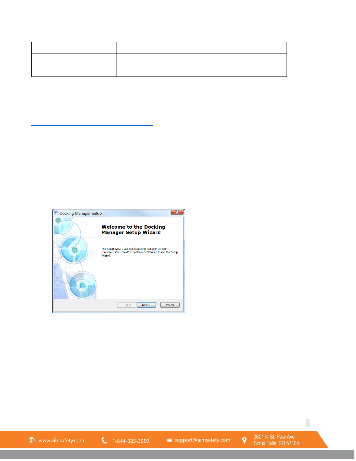
5.1.2 Install the software................................................................................................................................... 9
5.2 Connect to the Calibration Station................................................................................................................. 11
5.2.1 Connect Using PM Link........................................................................................................................... 11
5.2.2 Connect Using USB Disk.......................................................................................................................... 12
5.3 Use the Software............................................................................................................................................ 12
5.3.1 Station Tab.............................................................................................................................................. 13
5.3.2 PM100 Tab.............................................................................................................................................. 15
5.3.3 Logs Tab .................................................................................................................................................. 18
5.3.4 Time Tab ................................................................................................................................................. 20
6 AimSafety Product limited warranty ...................................................................................................................... 21
Technical Support Contact Information ....................................................................................................................... 21
General Contact Information........................................................................................................................................ 21

PM100 Bump Test and Calibration Station
REV – 1.0 [34-2900-0513-2 ] 3 |Page
1General Safety Information
1.1 List of warnings
WARNING
Each person using this equipment must read and understand the information in this
user manual before use. Use of this equipment by untrained or unqualified persons or
use that is not in accordance with this user manual, may adversely affect product
performance.
This equipment may not function effectively below 41°F or above 104°F (5°C or above
40°C). Using the equipment outside of this temperature range may adversely affect
product performance.
This equipment helps ensure gas monitors can accurately test for the presence and
concentration level of a certain specified airborne gas. Misuse may produce an
inaccurate reading, which means that higher levels of the gas being monitored may be
present and could result in overexposure and cause serious injury or death. For proper
use, see supervisor or User manual, or contact Technical Support at 1-844-325-3050.
Do not disassemble unit or attempt to repair or modify any component of this
instrument. This instrument contains no user serviceable parts, and substitution of
components may impair product performance.
Using a certified gas with a concentration other than the one listed for this equipment
when conducting a calibration verification test (bump test) will produce inaccurate
readings. This means that higher levels of the gas being monitored may be present and
could result in overexposure. For proper use, see supervisor or User manual, or
contact Technical Support at 1-844-325-3050.
The following steps must be performed when conducting a calibration verification test
(bump test) to ensure proper performance of the monitor. Failure to do so may
adversely affect product performance.
•When performing a calibration verification test (bump test) only use certified
calibration gas at the required concentration level.
•Do not test with expired calibration gas.
•Do not cover or obstruct display or visual alarm cover.
•Ensure sensor inlets are unobstructed and are free of debris
Failure to follow instructions outlined in this user manual can result in sickness or
death.

PM100 Bump Test and Calibration Station
REV – 1.0 [34-2900-0513-2 ] 4 |Page
2Use Instructions and Limitations
2.1 Use For
The AimSafety Bump/Calibration Station for PMR100Ris an all-in-one testing/calibration station for PMR100Rportable gas
monitors. The Bump-Calibration Station utilizes the IR communication of the PMR100RMonitors to perform testing and
calibration by pressing only a single button. Operation of the station only requires the use of two buttons. Learning
to use the station takes only minutes.
It is designed to quickly perform bump tests/calibration for multiple PMR100Rmonitors. It can test/calibrate up to four
detectors simultaneously, which reduces the testing time and gas usage. The Bump-Calibration Station will work
with PMR100RHR2RS, CO, and OR2Rmonitors.

PM100 Bump Test and Calibration Station
REV – 1.0 [34-2900-0513-2 ] 5 |Page
2.2 Features
•Simultaneously test four PMR100Rgas monitors
•Rechargeable internal battery lasts up to 1000 bump tests on a single charge
•Internal gas cylinder regulator and pressure gauge
•USB flash drive for bump test and event log storage
•Configuration using the Docking Manager software
•Firmware updates using the docking manager software
•Rugged case
•Computer not required for normal operation
WARNING
Each person using this equipment must read and understand the information in this
user manual before use. Use of this equipment by untrained or unqualified persons or
use that is not in accordance with this user manual, may adversely affect product
performance.
2.3 Specifications
•Size: 18.50" x 16.14" x 8.66" (47 x 41 x 22cm)
•Weight: 18 Lbs. (8.2kg) Without cylinder
•Operating Temperature:41° to 104°F (5° to +40°C)
•Warranty: 2-years
•Battery Type: Rechargeable Lithium Ion
•Battery life: ~1000 Bump Tests
•LEDs: 5 red/green/orange LEDs (1 for each bay, 1 for power indicator)
•Memory: USB 8GB Standard
•Log Capacity: Approximately Up to 10 million tests (with 8GB removable USB memory)
•Functions performed: Bump Test and Calibration
•Information Stored: Bump/Cal Logs, Individual Monitor Event Logs, Firmware and Unit Configurations
•Gases Available: CO, H2S and O2
•Gas Cylinder: Compatible with 58L cylinders
•Charging Adaptor: 12V DC @ 3A

PM100 Bump Test and Calibration Station
REV – 1.0 [34-2900-0513-2 ] 6 |Page
3Operation
The Bump-Calibration Station is operated using only two buttons.
3.1 Power
To turn on the power,
1. Press either the Bump Test or the Calibration button for one second.
2. The Power LED will initially turn on to orange, then switch to green when the unit is ready. If the unit has a
low battery, the power LED will switch to red.
3. If the USB is full or is not detected, the power LED will initially flash orange for five seconds.
To turn off the power,
1. Press and hold the Bump Test and Calibration button simultaneously for one second.
2. The power LED will shut off indicating the unit has been switched to sleep mode.
NOTE: The unit will automatically switch to sleep mode after 5 minutes of inactivity.
3.2 LEDs
There are 5 LEDs on the Bump-Calibration Station which indicate the operation status.
LED
Color
Description
Operation Status
Unit LEDs
On
Testing
On
Test Failed
On
Test Passed
Blinking (5 sec.)
Communicating
Power LED
On
Ready
Blinking (5 sec.)
No USB/USB Full
On
Low Battery
3.3 Charge Battery
The charging port is located on the left side of the unit. The unit comes with a DC adapter which can be used to
charge the unit using a 110V power supply. A full charge will take approximately 3 hours and will last for
approximately 1000 bump tests.
3.4 Gas Cylinder Installation
Gas cylinders are available in single gas and multi-gas concentrations. They must have the C10 fitting on them. Gas
cylinders are available through local distribution or from AimSafety.
To install a new gas cylinder,
1. Remove the two thumbscrews located between the handle and the edge of the case.
2. Lift the handle to open the gas cylinder compartment.
3. Attach the cylinder to the gas regulator by threading the bottle into the fitting until tight.
4. Secure the cylinder with the three cylinder straps.
5. Close the cylinder compartment.
6. Check the pressure gauge to confirm adequate pressure.
7. Replace the two thumbscrews.

PM100 Bump Test and Calibration Station
REV – 1.0 [34-2900-0513-2 ] 7 |Page
The Gas Expiration date and Gas Bottle Lot # can be recorded using the Bump-Calibration Station Manager software
(See Section 5.3.1.1 Station Info).
3.5 Exhaust Port
The exhaust port is located on the left side of the unit next to the charging port. During an active test, the test gas
will exit the unit through this port. Optionally, tubing can be attached to the exhaust port to direct the used test gas
to a suitable location.
4Testing
Place up to four activated monitors in the bays for testing. Confirm that the installed test gas cylinder matches the
gas types required by the monitors being tested. The Bump-Calibration Station can test monitors with different gas
types at the same time if using a multi-gas cylinder.
Every test (Bump test and Calibration) can also automatically perform the following optional operations (See Section
5.3.1.2 Enable/Disable Function):
•Upgrade each monitor’s firmware (if required)
•Test each monitor’s beeper
•Configure each monitor’s user options (as required)
•Download each monitor’s logs and save them to the USB memory
•Record the test to the USB memory
NOTE: All empty bays must have a rubber cap installed before a test can be performed. Without the rubber cap
installed, excess test gas will leak out of the empty bay.
4.1 Bump Test
All monitors need to be periodically tested with a known concentration of gas to verify the sensor is responding
correctly to the target gas. This test is called a bump test.
To perform a bump test,
1. Place the monitor(s) into the bays.
2. With the Bump-Calibration Station powered on, press the Bump Test button for one second to start the test.
The unit LED will turn Orange when the test has started.
3. The unit LED will remain Orange while the test is in progress. A bump test will take approximately 20
seconds.
4. When the test is complete, the unit LED will turn Green for a successful test or Red if it fails.
5. Remove the monitor from the bay.
NOTE: Any monitors that fail a bump test will require calibration before use.
4.2 Calibration
Calibration is the process of adjusting the sensor’s response by using a specific concentration of calibration gas.
Sensors will lose accuracy over time for a variety of reasons. Therefore, it is important to perform a full calibration
periodically to ensure the sensors response to the target gas are accurate.
A proper calibration requires a Zero Calibration (also called a Fresh Air Calibration) and a Span Calibration.

PM100 Bump Test and Calibration Station
REV – 1.0 [34-2900-0513-2 ] 8 |Page
The Bump-Calibration Station performs the Span Calibration but does not perform the Zero Calibration.
It is recommended to perform a Zero Calibration prior to performing the Span Calibration using the Bump-
Calibration Station. A Zero Calibration can be done using the PMR100Rmonitor interface or with the assistance of the
PM Link.
To perform a Span Calibration,
1. Place the monitor(s) into the bays.
2. Press the calibration button for one second to start the test. The unit LED will turn Orange when the test has
started.
3. The unit LED will remain Orange while the calibration is in progress. The calibration will take approximately
60 seconds for 0R2Rand 90 seconds for CO and HR2RS.
4. When the calibration is complete, the unit LED will turn Green for a successful calibration or Red if it fails.
5. Remove the monitor from the bay.
NOTE: Do not use a monitor that fails a calibration.
4.3 Test Troubleshooting
4.3.1 Unit LED does not turn on or test is not performed
•Clean monitor IR window
•IR interference (bright lights/sunlight)
•Monitor in gas alarm state
4.3.2 All tests fail
•Gas cylinder empty – Check pressure gauge. Gas pressure should read at least 100 psi for proper operation.
•Gas Expired – Gas expiration date is located on the gas cylinder.
•Wrong gas concentration(s).
•Wrong gas type.
•If a monitor fails 3 consecutive test attempts, please contact AimSafety Technical Support.
4.3.3 Test results not stored
•USB drive not installed or corrupted – Power LED will flash orange for five seconds during startup.
•USB drive full – Power LED will flash orange for five seconds during startup.
5Station Manager Software
The Bump-Calibration Station Manager software is used to configure the Bump-Calibration Station. The software can
make changes to the Bump-Calibration Station settings using a PM Link device or the included USB Disk.
Not all software features are available when using the USB Disk. The table below shows the available features:
Feature
Available with PM Link?
Available with USB Disk?
PM
R100R
configuration
Yes
Yes
Update PM
R100R
firmware files
Yes
Yes
Update Bump-Calibration
Station firmware files
Yes
Yes

PM100 Bump Test and Calibration Station
REV – 1.0 [34-2900-0513-2 ] 9 |Page
Add test gas information
Yes
Yes
Retrieve log files
Yes
Yes, using file explorer
Set time and date
Yes
No
5.1 Download and Installation
5.1.1 Download the software
Download the Bump-Calibration Station Manager software from the following link:
32TUhttps://www.macurco.com/?ddownload=2090U32T
Save the file to a place you will remember.
5.1.2 Install the software
To install the software,
1. Navigate to the saved file.
2. Double-click the file to run the installer.
3. You may receive a security warning. Click Run or Run Anyway to continue with the installation.
4. The Docking Manager Setup wizard will start. Click Next.

PM100 Bump Test and Calibration Station
REV – 1.0 [34-2900-0513-2 ] 10 |Page
5. Now select the installation folder. The default folder is the best option for most people. Click Next.
6. The installation is ready to begin. Click Install.
7. You may receive a warning. Click Yes to continue.

PM100 Bump Test and Calibration Station
REV – 1.0 [34-2900-0513-2 ] 11 |Page
8. When the installation is complete, click Finish to exit the Setup Wizard.
5.2 Connect to the Calibration Station
When the Bump-Calibration Station Manager software is first opened, the fields are grayed out. The software must
be connected to the Bump-Calibration Station before it can be used. There are two methods to connect the
software to the Bump-Calibration Station: A PM Link or the included USB Disk can be used.
5.2.1 Connect Using PM Link
The Bump-Calibration Station can be conveniently configured using the PM Link device. The unit can communicate
with the PM Link device using the IR communication in Unit 1 bay.
To connect using the PM Link,
1. Plug the PM Link device into a USB port on your computer.
2. Place the PM Link device in Unit 1 bay with the IR lens of the PM Link facing the IR lens of the Unit 1 bay.
3. Make sure the Bump-Calibration Station power is on indicated by the green Power LED.
4. Open the Bump-Calibration Station Manager software.
5. Make sure the “IR” option at the top of the software interface is selected.

PM100 Bump Test and Calibration Station
REV – 1.0 [34-2900-0513-2 ] 12 |Page
6. Press OPEN in the upper right corner of the software interface.
NOTE: If the software is opened before the PM Link device is plugged into the computer, a “Port open fail”
message may popup. If this occurs, close the software and reopen it.
7. The communication light on the PM Link device will begin to flash rapidly.
8. After several seconds, the current Bump-Calibration Station settings will be displayed on the interface and a
“Read complete” message will be displayed.
If the PM Link device fails to communicate with the Bump-Calibration Station after 20 seconds, a “Send timeOut”
message will be displayed. Check to make sure the Bump-Calibration Station power is on, and that the PM Link IR
screen is aimed at the IR screen of Unit 1 bay.
5.2.2 Connect Using USB Disk
Alternatively, the Bump-Calibration Station can be configured using the included USB Disk. The USB Disk will need to
be removed from the Bump-Calibration Station and plugged into a USB port on the computer.
To connect the USB Disk to the Bump-Calibration Station Manager software,
1. Turn off the power to the Bump-Calibration Station by pressing the Bump Test and Calibration buttons
simultaneously.
2. Remove the two thumbscrews located between the edge of the case and the handle.
3. Lift the handle to open the gas cylinder compartment.
4. The USB Disk is located on the right side of the bottom of the compartment. Remove the USB Disk by simply
pulling it out.
5. Plug the USB Disk into a USB port on your computer.
6. Open the Bump-Calibration Station Manager software.
7. Select the USB Disk option at the top of the software interface.
8. Navigate to the location of your USB Disk. Click OK.
5.3 Use the Software
Once connected, the software interface will display the current settings of the connected Bump-Calibration Station
and fields that can be edited will no longer be grayed out. It should look similar to the image below.
NOTE: The Logs and Time tabs will not be available if connected using the USB Disk.

PM100 Bump Test and Calibration Station
REV – 1.0 [34-2900-0513-2 ] 13 |Page
5.3.1 Station Tab
The Station tab is displayed when the software opens (as shown above). It shows information about the Bump-
Calibration Station, information about the installed gas cylinder, configuration of the operation of the Bump-
Calibration Station, and the Bump-Calibration Station firmware upgrade interface.
NOTE: No changes will be saved to the Bump-Calibration Station until the Write button is pressed (see 5.3.1.1).
5.3.1.1 Station Info
Serial Number – Cannot be changed. It uniquely identifies the Bump-Calibration Station unit.
Version – The firmware version installed on the Bump-Calibration Station.
Auto Power-off – Determines the idle time before the Bump-Calibration Station automatically switches to sleep
mode. Can be set from 1-3600 seconds. Default is 300 seconds.
Maximum Bump Time – Determines the maximum time allowed for a Bump Test. If the PMR100Rdevice fails to
properly respond before the time expires, the test will stop, and the device will fail the test. Can be set from 20-120
seconds (default is 20 seconds).

PM100 Bump Test and Calibration Station
REV – 1.0 [34-2900-0513-2 ] 14 |Page
Docking Time Auto Sync – If checked, the time on the Bump-Calibration Station will be synced to the computer
time. If unchecked, the time can be manually adjusted within the Time tab.
Location A custom location can be added up to 12 alphanumeric characters. This can be useful to keep data from
multiple Bump-Calibration Stations organized.
Gas Expiration – Displays the expiration date of the installed gas cylinder. Update this field when a new gas cylinder
is installed. Gas expiration date can be found on the gas cylinder.
Gas Bottle Lot # - Displays the lot number of the installed gas cylinder. The gas cylinder lot number can be found on
the gas cylinder. Update this field when a new gas cylinder is installed.
Info Read/Write – Press Read to download and display the current settings of the Bump-Calibration Station.
Pressing Read will discard any unsaved changes in the Station tab. Press Write to upload the settings currently
displayed on the software to the Bump-Calibration Station. No changes will be saved to the Bump-Calibration
Station until the Write button is pressed.
5.3.1.2 Enable/Disable Function
When the Bump-Calibration Station performs a bump test or calibration on a PMR
100Rdevice, it can optionally perform
other maintenance tasks simultaneously.
Calibrate – If the Calibrate box is unchecked, the calibrate function of the Bump-Calibration Station will be disabled.
With the calibrate function disabled, pressing the Calibrate button will not calibrate the monitor, but it will update
configuration or firmware if the option is enabled. The power LED will turn orange for 5 seconds, then return to
green.
Bump Tests – If the Bump Tests box is unchecked, the Bump Test function of the Bump-Calibration Station will be
disabled. With the Bump Test function disabled, pressing the Bump Test button will not test the monitor, but it will
update configuration or firmware if the option is enabled. The power LED will turn orange for 5 seconds, then return
to green.
Update PM100 Config – If this box is checked, the Bump-Calibration Station will update the PMR100Rconfiguration
settings (See Section 5.3.2.1 PM100 Configuration Options) when the Bump Test or Calibration button is pressed.
Update PM100 Firmware – If this box is checked, the Bump-Calibration Station will upgrade the PMR100Rfirmware
when the Bump Test or Calibration button is pressed. It is not necessary to upgrade the PMR100Rfirmware every time
the monitor is tested. It is only necessary when a newer version of the firmware is available. To update the firmware
file saved on the Bump-Calibration Station, see Section 5.3.2.4 PM100 Firmware Upgrade.
Bump Result Decision – The dropdown list is selectable for “Beep”, “Concentration”, or “Beep + Concentration”.
The “Beep” option will run the bump test until the alarm condition is met and the audible alarm is detected.

PM100 Bump Test and Calibration Station
REV – 1.0 [34-2900-0513-2 ] 15 |Page
The “Concentration” option will run the bump test until the test gas concentration is verified. If the units are in
Stealth Mode, the Concentration option will be required for a successful bump test.
The “Beep + Concentration” option will run the bump test until the audible alarm is detected and the test gas
concentration is verified.
5.3.1.3 Bump-Calibration Station Firmware Upgrade
To upgrade the Bump-Calibration Station firmware,
1. Click Browse.
2. Navigate to the location of the firmware file.
3. Click Open.
4. The software interface will show the file path of the new firmware in the Station Firmware Upgrade field.
Click Write to write the new firmware to the Bump-Calibration Station.
5.3.2 PM100 Tab
The Bump-Calibration Station and Bump-Calibration Station Manager software can be used to quickly make
configuration changes for multiple PMR100Rdetectors. The PM100 tab in the Bump-Calibration Station Manager

PM100 Bump Test and Calibration Station
REV – 1.0 [34-2900-0513-2 ] 16 |Page
software shows the available configuration options for PMR100Rdevices. All configuration settings can be set to be
simultaneously updated during each bump test or calibration (see Section 5.3.1.2 Enable/Disable Function).
5.3.2.1 PM100 Configuration Options
Each configuration option can be enabled/disabled using the checkbox on the left side. Disabling the option will not
disable the feature in the PMR100Rmonitor. It will only prevent the Bump-Calibration Station from changing the
existing setting in each PMR
100Rmonitor.
Note: Although the software will perform a “Read” operation when opening, If the device is not in place, the “Read”
operation may need to be performed once the software is opened to display the configuration of the device.
User ID – The User ID field can be used to add a custom message.
Calibration Interval (Days) – The Calibration reminder can be configured from n/a (Off) to 365 days.
Bump Interval (Days) – The Bump Test reminder can be configured from n/a (Off) to 365 days.
Self-Test Interval (hours) – The Self-Test reminder can be configured to n/a (Off) or between 8 hours to 20
hours.
Low Alarm – This is the first (low for OR2R) set point that activates the monitor’s alarms.
High Alarm – This is the second (high for OR2R) set point that activates the monitor’s alarms.
Display – Choose whether the monitor display shows the current gas reading or the remaining sensor life.
5.3.2.2 Gas Concentration

PM100 Bump Test and Calibration Station
REV – 1.0 [34-2900-0513-2 ] 17 |Page
This field allows you to enter the gas concentration(s) of the test gas cylinder installed in the Bump-Calibration
Station. This is necessary for proper testing and calibration of PMR100Rmonitors. There are fields available for H2S, CO,
and O2.
5.3.2.3 PM100 Option Info Read/Write
IMPORTANT: Any changes made to the PM100 tab will not be saved to the Bump-Calibration Station until the
“Write” button is clicked.
To write the data from the PM100 tab to the Bump-Calibration Station, press Write.
To read the current PMR100Rconfiguration options saved in the Bump-Calibration Station, press Read.
NOTE: Pressing Read will cause any unsaved changes on the PM100 tab to be lost.
5.3.2.4 PM100 Firmware Upgrade
The Bump-Calibration Station can be used to upgrade the PMR100Rfirmware. The Bump-Calibration Station can keep a
copy of the PMR100Rfirmware saved on its USB Disk. PMR100 Rmonitors require a firmware file that is specific to the
monitor’s gas type. If there is a new firmware version, the file can be found at https://macurco.com/downloads/.
To update the PMR100Rfirmware file,
1. Press Browse to open the file explorer.
2. Navigate to the PMR100Rfirmware file.
3. Press Open.
4. Press Write. The PMR100Rfirmware file will be saved to the USB Disk of the Bump-Calibration Station.

PM100 Bump Test and Calibration Station
REV – 1.0 [34-2900-0513-2 ] 18 |Page
5.3.3 Logs Tab
Logs are stored on the USB Disk and can be viewed on a computer using the Bump-Calibration Station Manager
software. The log files will be formatted as .csv files (comma separated values) for easy viewing and manipulation
with spreadsheet software. A log file will be created for each PMR100Rmonitor used in the Bump-Calibration Station. A
single log file will be created for the Bump-Calibration Station.
NOTE: The Logs tab is not available if connected via USB Disk. Instead, the log files can be viewed and saved directly
by navigating to the “Logs” folder in the USB Disk.
5.3.3.1 View Log Files
To view a list of the log files, click Refresh while connected to the Bump-Calibration Station. The log file names will
appear in the list box and a “Log file receive success” message will pop-up when the list is complete. Log file names
are based on the serial number of the device.

PM100 Bump Test and Calibration Station
REV – 1.0 [34-2900-0513-2 ] 19 |Page
5.3.3.2 Save Logs to Computer
The log files can be saved to the computer.
To save the log files to the computer,
1. Select the desired log files to save. Click the Select All check box to select or deselect all log files at once.
Individual log files can be selected by clicking on their respective check box.
2. Click Local Save.
3. A Browse window will open. Navigate to the desired save location. If saving many log files, it may be
advisable to create a folder for the log files.
4. Press OK. The download will start.
5. When the download is complete, a “Log data save success” message will pop-up.
5.3.3.3 Log Information
The log files are saved in a .csv file format. They can be opened by any spreadsheet software.
Each time a test is performed, a log similar to the image below will be created in the Bump-Calibration Station log
file.
Each PMR100Rmonitor that is tested using the Bump-Calibration Station will generate its own log file. The image below
shows the information in a sample log file with two test entries.
Other manuals for AimSafety PM 100
1
Table of contents
Other Macurco Test Equipment manuals
Popular Test Equipment manuals by other brands

Sealey
Sealey BT2013.V4 instructions

Matatakitoyo Torque Tools
Matatakitoyo Torque Tools Metric ETT-15N Operation manual

Lincoln
Lincoln Mityvac MV4534 user manual

Nidec
Nidec Shimpo DT-315AEB instruction manual

Fluke
Fluke 990DSL user guide

Gossen MetraWatt
Gossen MetraWatt METRAVOLT 12D+L operating instructions