Madas RG/2MC User manual

MADE IN ITALY
II 2G - II 2D
0497
REGOLATORE DI PRESSIONE PER GAS
GAS PRESSURE REGULATOR
REGULATEUR DE PRESSION POUR GAZ
REGULADOR DE PRESIÓN PARA GAS
RG/2MC - FRG/2MC
CHAPTER
4.1e
SEC TION
4
Madas Technical Manual - 4|4.1e - REV. 0 of 1th May 2018 - RG/2MC - FRG/2MC
IT EN FR ES
Range pressione di esercizio
Operating pressure range
Plage de pression de fonctionnement
Rango de la presión de funcionamiento
Pe: 1÷2 bar
Attacchi filettati / Threaded connections
Raccords filetés / Conexiones roscadas
DN 15 - DN 20 - DN 25 - DN 32 - DN 40 - DN 50
Attacchi filettati a 90°/ Threaded connections at 90°
Raccords filetés à 90° / Conexiones roscadas a 90°
DN 15 - DN 20 - DN 25 - DN 32 - DN 40 - DN 50
Attacchi flangiati/ Flanged connections
Raccords à brides / Conexiones embridadas
DN 25* - DN 32 - DN 40 - DN 50 - DN 65 - DN 80 - DN 100
* su richiesta
con flange girevoli
*
with swivel flanges
on request
*
sur demande
avec brides tournantes
*
bajo petición
con bridas locas
Norma di riferimento / Reference standard
Norme de référence / Patrón de referencia EN 88-2
In conformità a
In conformity with
Conforme a
Conforme
Direttiva PED
2014/68/UE
PED Directive
2014/68/EU
Directive PED
2014/68/UE
Directiva PED
2014/68/UE

2
ES FR EN IT
Madas Technical Manual - 4|4.1e - REV. 0 of 1th May 2018RG/2MC - FRG/2MC
INDICE INDEX INDEX ÍNDICE
pag.
Italiano ........................................................................................................................................................3
English ........................................................................................................................................................10
Français ......................................................................................................................................................17
Español .......................................................................................................................................................24
Disegni - Drawings - Dessins - Diseños ............................................................................................................32
Dimensioni (tabella 1a - 1b) ...........................................................................................................................41
Dimensions (table 1a - 1b) .............................................................................................................................
Dimensions (tableau 1a - 1b) ..........................................................................................................................
Dimensiones (tabla 1a - 1b) ..........................................................................................................................
Caratteristiche molle di regolazione (tabella 3) ....................................................................................................43
Regulation spring data (table 3) .......................................................................................................................
Caracteristiques des ressorts de reglage (tableau 3) ...........................................................................................
Características muelles de regulación (tabla 3) ...................................................................................................
Diagramma - Diagram - Diagramme - Diagrama Δp.............................................................................................44
Codifica prodotto / Product encoding / Codification du produit / Codificación del producto.......................................46

10
ES FR EN IT
RG/2MC - FRG/2MC Madas Technical Manual - 4|4.1e - REV. 0 of 1th May 2018
1.0 GENERAL INFORMATION
This manual shows you how to safely install, operate and use the device.
The instructions for use ALWAYS need to be available in the facility where the device is installed.
ATTENTION: installation/maintenance needs to be carried out by qualified staff (as explained in
section 1.3) by using suitable personal protective equipment (PPE).
For any information pertaining to installation/maintenance or in case of problems that cannot be solved with the instructions,
contact the manufacturer by using the address and phone numbers provided on the last page.
1.1 DESCRIPTION
Device which supplies a preset and constant “downstream” pressure value (Pa) (within the intended operating limits) when the
inlet pressure (Pe) and/or the flow rate (Q) changes. The compensated obturator ensures precision when adjusting the outlet
pressure (Pa) even in the case of high and sudden variations in the inlet pressure.
It is fitted with:
• a spring to adjust the outlet pressure;
• a safety membrane;
• an output pressure test nipple (with some exceptions) to control the outlet pressure (Pa). On some models the pressure
test nipple is also present on the input;
It can also be supplied with a built-in filtering element (FRG/2MC models).
Available 90° connections for threaded connections from DN 15 to DN 50.
Reference standards: EN 88-2 – EN 13611. Component for industrial use on industrial sites.
1.2 KEY OF SYMBOLS
ATTENTION: Attention
is drawn to the technical
details intended for
qualified staff.
DANGER:
In the event of
inobservance, this may cause damage
to tangible goods, to people and/or pets.
DANGER: In the event
of inobservance, this may
cause damage to tangible
goods.
1.3 QUALIFIED STAFF
These are people who:
•Are familiar with product installation, assembly, start-up and maintenance;
•Know the regulations in force in the region or country pertaining to installation and safety;
•Are trained in first aid.
1.4 USING NONORIGINAL SPARE PARTS
•To perform maintenance or change parts (e.g. spring, filter element, etc.) ONLY manufacturer-recommended parts can be
used. Using different parts not only voids the product warranty, it could compromise correct device operation.
•The manufacturer is not liable for malfunctions caused by unauthorised tampering or use of non-original parts.
1.5 IMPROPER USE
•The product must only be used for the purpose it was built for.
•It is not allowed to use fluids other than those expressly stated.
•The technical data set forth on the rating plate must not, under any circumstances, be exceeded. The end user or installer is in
charge of implementing correct systems to protect the device, which prevent the maximum pressure indicated on the rating plate
from being exceeded.
•The manufacturer is not responsible for any damage caused by improper use of the device.

11
IT EN FR ES
RG/2MC - FRG/2MCMadas Technical Manual - 4|4.1e - REV. 0 of 1th May 2018
2.0 TECHNICAL DATA
• Use : non-aggressive gases of the three families (dry gases)
• Ambient temperature (TS) : -15 ÷ +60 °C
• Operating pressure range (Pe) : 1÷2 bar
• Accuracy class : AC10 (P2 ± 10%)
• Closing pressure class : SG30 (P2 + 30%)
• Mechanical resistance : Group 2 (according to EN 13611)
• Rp threaded connections in line : (DN 15 - DN 20 - DN 25 - DN 32 - DN 40 - DN 50) according to EN 10226
• Rp threaded connections at 90° : (DN 15 - DN 20 - DN 25 - DN 32 - DN 40 - DN 50) according to EN 10226
• Flanged connections that can couple with
PN 16 flanges :
(DN 25* - DN 32 - DN 40 - DN 50 - DN 65 - DN 80 - DN 100) ISO 7005 / EN 1092-1
• NPT threaded or ANSI 150 threaded connections
: on request
• Filter element (only models FRG/2MC) : filtering 50µm
• In compliance with : PED Directive 2014/68/EU - ATEX Directive 2014/34/EU
* DN 25 with swivel flanges on request.
2.1 MODEL IDENTIFICATION
RG/2MC: Pressure regulator for gas without filter - (connections in line)
FRG/2MC: Pressure regulator for gas with built-in filter - (connections in line)
RG/2MCR: Pressure regulator for gas without filter - (connections at 90° see figure 2 and 4)
FRG/2MCR: Pressure regulator for gas with built-in filter - (connections at 90° see figure 2 and 4)
3.0 COMMISSIONING THE DEVICE
3.1 OPERATIONS PRIOR TO INSTALLATION
•It is necessary to close the gas upstream of the device prior to installation;
•Make sure that the line pressure DOES NOT EXCEED the maximum pressure declared on the product label;
•Protective caps (if any) must be removed prior to installation;
•The pipes and inside of the device must be clear of any foreign bodies;
•IMPORTANT: to avoid possible pumping and/or disturbances in the gas flow, a straight pipe section equal to at least 5
DN must be installed (downstream of the regulator).
•IMPORTANT: install manual gas closing devices (e.g. ball valves) upstream and downstream of the regulator to protect
it from any pipe leak test;
If the device is threaded:
•make sure that the pipe thread is not too long, to prevent damaging the body of the device when screwing it on;
If the device is flanged:
•make sure the inlet and outlet counter-flanges are perfectly coaxial and parallel in order to prevent unnecessary
mechanical stress to the body. Also calculate the space to insert the seal gasket;
•With regard to tightening operations, equip yourself with one or two calibrated torque wrenches or other controlled locking
tools;
•The safety regulations on handling loads in force in the country of installation must be complied with. If the device to
be installed exceeds the weight allowed, suitable mechanical equipment and adequate slings must be used. Necessary
precautions must be taken during the handling phases so as not to damage/ruin the external surface of the device.
•If the regulator is not fitted with a filter, it is advisable to install an adequate filter upstream;
•With outdoor installation, it is advisable to install a protective roof to prevent rain from oxidising or damaging parts of the
device.
•According to the plant geometry, check the risk of an explosive mixture arising inside the piping;
•If the regulator is installed near other devices or as part of an assembly, compatibility between the regulator and
these devices must be evaluated beforehand;
•Provide a protection against impacts or accidental contacts if the device is accessible to unqualified personnel.

12
ES FR EN IT
RG/2MC - FRG/2MC Madas Technical Manual - 4|4.1e - REV. 0 of 1th May 2018
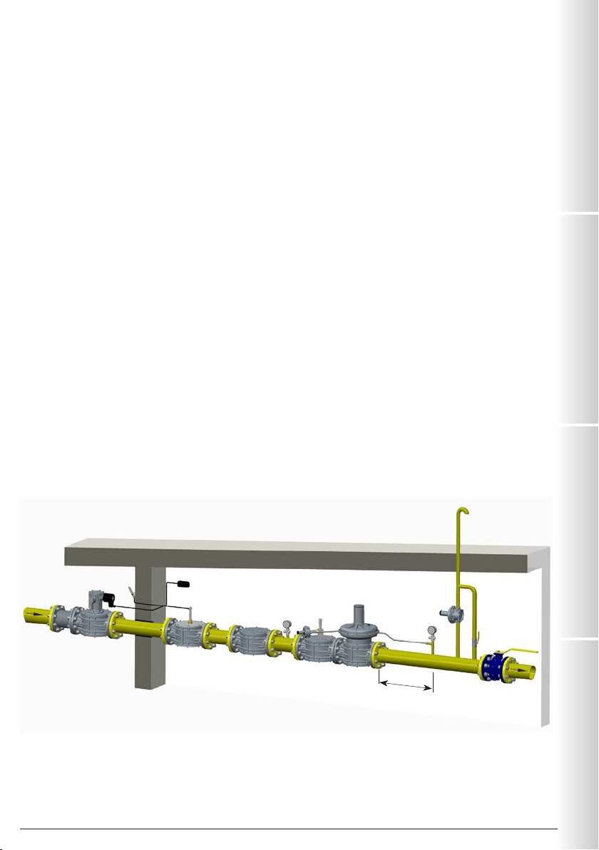
3.2 INSTALLATION (see example in 3.4)
Threaded devices:
•Assemble the device by screwing it, with the due seals, onto the plant with pipes and/or fittings whose threads are consistent
with the connection being attached.
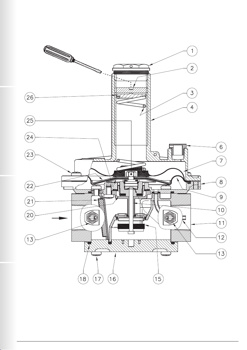
•Do not use the neck of the top cover (4) as a lever to help you screw it on, only use the specific tool;
•The arrow, shown on the body (11 ) of the device, needs to be pointing towards the application;
Flanged devices:
•Assemble the device by flanging it, with the due seals, onto the plant with pipes whose flanges are consistent with the
connection being attached. The gaskets must be free from defects and must be centred between the flanges;
•If, after installing the gaskets, there is still an excessive space in between, do not try to reduce the said gap by excessively
tightening the bolts of the device;
•The arrow, shown on the body (11 ) of the device, needs to be pointing towards the application;
•Insert the relative washers inside the bolts in order to prevent damage to the flanges during tightening;
•When tightening, be careful not to “pinch” or damage the gasket;
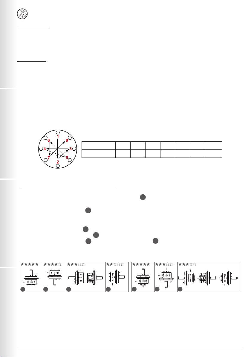
•Tighten the nuts or bolts gradually, in a “cross” pattern (see the example below);
•Tighten them, first by 30%, then by 60% and finally 100% of the maximum torque (see the table below according to
EN
13611);
Diameter DN 25 DN 32 DN 40 DN 50 DN 65 DN 80 DN 100
Max. torque (N.m) 30 50 50 50 50 50 80
•Tighten each nut and bolt again clockwise at least once, until the maximum torque has been achieved uniformly;
•Common procedures (threaded and flanged devices):
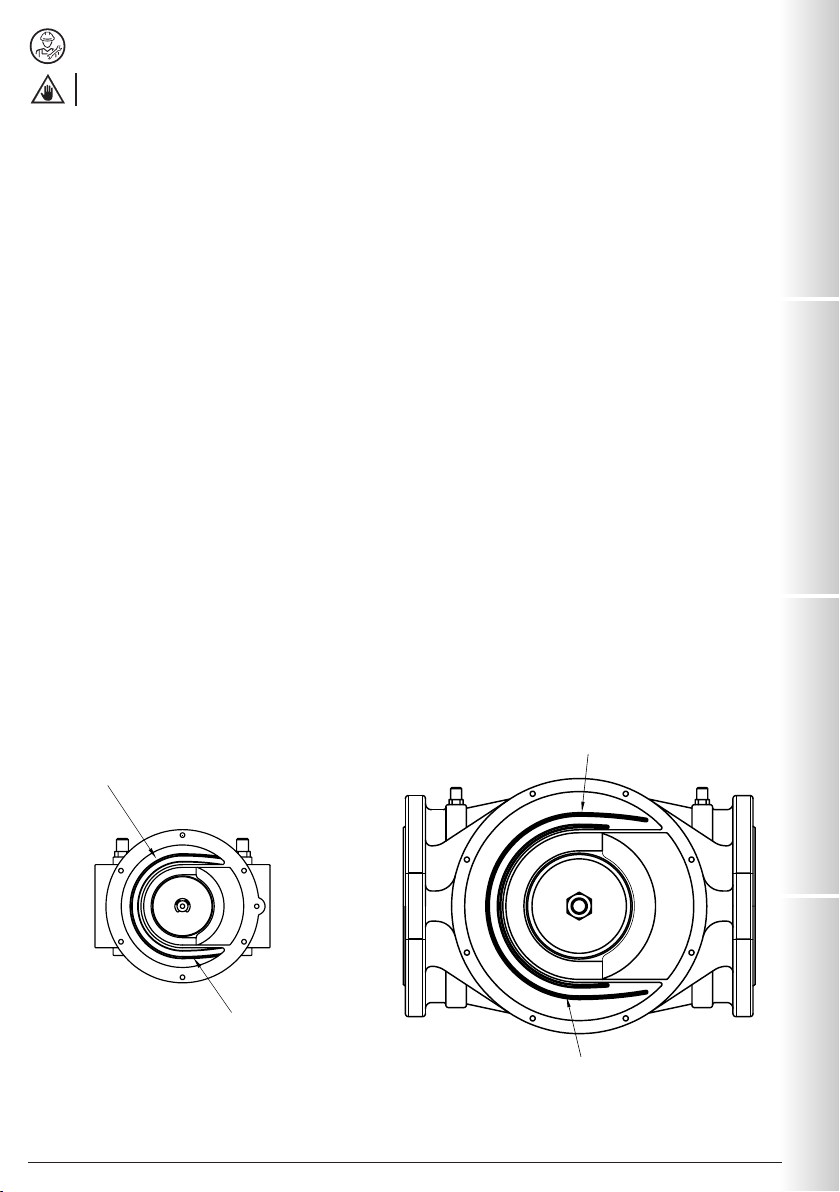
•The regulator is normally positioned before the utility. Primarily evaluate the possibility of installing the regulator as shown in
the installation example in 3.4, namely in an optimal position pos. a(see figures below);
•Should this not be possible, the following factors must be considered:
1. if installed as shown in pos. bthe maximum Pa value declared on the rating plate could be less by a few mbar.
NOTE: for versions with 90° connections, it is recommended to install a filter after the regulator that protects it from
debris that could enter from downstream from above (due to gravity);
2. if installed as shown in pos. cthe life span of the product could be shorter than the duration that could be obtained
if installed in the optimal position a;
3. if installed as shown in pos. d, besides that indicated for pos. cit is recommended to install a filter after the
regulator that protects it from debris that could enter from downstream from above (due to gravity);
Connections in line 90° connections (closed line output)
a b dc a b c
•During installation, avoid debris or metal residues from getting into the device;
•To guarantee mechanical tension-free assembly, we recommend using compensating joints, which also adjust to the pipe’s
thermal expansion;
•If the device is to be installed in a ramp, it is the installer’s responsibility to provide suitable supports or correctly sized
supports, to properly hold and secure the assembly. Never, for any reason whatsoever, leave the weight of the ramp only on
the connections (threaded or flanged) of the individual devices;
•In any case, after the installation check the tightness of the system, avoiding to subject the membrane of the regulator
(therefore, the downstream pipe section) to a pressure higher than 300 mbar;

13
IT EN FR ES
RG/2MC - FRG/2MCMadas Technical Manual - 4|4.1e - REV. 0 of 1th May 2018
3.4 GENERIC EXAMPLE OF AN INSTALLATION
1. M16/RM N.C. Manual reset solenoid valve
2. SM jerk ON/OFF valve
3. FM gas filter
4. OPSO series MVB/1 MAX shut off valve
5. RG/2MC pressure regulator
6. MVS/1 relief valve
7. Pressure gauge and relative button
8. Vent valve
9. Ball valve
10. Gas detector
11. SM remote jerk ON/OFF valve lever control
12. Expansion joint/anti-vibration mount
3.3
INSTALLATION IN PLACES WHERE THERE IS THE RISK OF EXPLOSION (DIRECTIVE 2014/34/EU)
The regulator complies with Directive 2014/34/EU as a device of group II, category 2G and as device of group II, category
2D; consequently, it is suited for installation in zones 1 and 21 (besides zones 2 and 22) as classified in Annex I of Directive
99/92/EC.
The regulator is not suited for use in zones 0 and 20 as defined in the aforementioned Directive 99/92/EC.
To determine the qualification and size of the danger zones, please refer to standard IEC EN 60079-10-1.
If the device is installed and serviced in full compliance with all the conditions and technical instructions provided in this
document, it does not pose a source of specific hazards: in particular, under normal operating conditions, the regulator emits a
flammable substance into the atmosphere ONLY if both the working membrane (9) and the safety membrane (7) malfunction:
in which case (and only if so), the regulator constitutes a source of emission of explosive atmosphere of continuous degree
and, as such, it can generate danger zones 0, as defined in Directive 99/92/EC.
In particularly critical installation conditions (unattended areas, poor maintenance or poor ventilation) and especially if there
are potential sources of ignition and/or hazardous equipment near the regulator in regular operation, as they may generate
electric arcs or sparks, a preliminary assessment of the compatibility between the regulator and such equipment must be
carried out.
In any case, every useful precaution must be adopted so as to prevent the regulator from generating zones 0: for example,
annually verify regular operation, possibility of changing the degree of emission of the source or intervening on the external
explosive substance discharge. For this purpose the threaded hole of the top cover (4) can be connected to the outside (using
appropriate fittings and pipes) by removing the dust cap (6).
1
2
345
6
8
9
7
7
10
11
piping applicaon
discharge in open air
internal thermal unit
non-hazardous venlated zone*
external roof
12
* if the zone is ATEX classified follow that indicated in 3.3
5 DN

14
ES FR EN IT
RG/2MC - FRG/2MC Madas Technical Manual - 4|4.1e - REV. 0 of 1th May 2018
4.0 FIRST STARTUP
Before commissioning, verify that:
•all of the instructions on the rating plate, including the direction of flow, are observed;
•the holes of the dust cap (6) are not clogged.
•IMPORTANT: The leak test of the piping must be performed while avoiding to subject the membrane of the
regulator (therefore, the downstream pipe section) to a pressure higher than 300 mbar. Use special manual gas
closing devices to prevent damaging the regulator;
•The pressurisation manoeuvre of the equipment must be carried out very slowly so as to avoid possible damage.
NOTE: under no circumstances should a blind cap be placed instead of the dust cap (6) as the regulator may
not work;
•Open the downstream vent valve partially;
•Slowly open the upstream shut-off devices (e.g. solenoid valves, OPSO shut-off valve, etc.);
•Wait until the downstream pressure stabilises at the calibration value Pa of the spring (indicated on the rating plate);
•Close the vent valve;
•Check the tightness of all the system gaskets and check the internal/external tightness of the regulator;
•Open the downstream shut-off valve very slowly;
•Check the operation of the regulator.
4.1 - RECOMMENDED PERIODIC CHECKS
•Use a suitable calibration tool to ensure the bolts are tightened as indicated in 3.2;
•Check the tightness of the flanged/threaded connections on the system;
•Check the tightness and operation of the regulator;
It is the responsibility of the final user or installer to define the frequency of these checks based on the severity of the service
conditions.
4.2 - ADJUSTING THE OUTLET PRESSURE
Before starting the system, make sure that the spring supplied with the regulator is suitable for the desired adjustment
pressure. The outlet pressure Pa (unless specifically requested) is factory set with the top cover (4) positioned as shown in
3.2 aand with the adjustment screw (2) set approximately at the minimum calibration value.
If the regulator is installed in different positions, check and reset the outlet pressure Pa.
Adjust the outlet pressure as follows:
•Unscrew the cap (1);
•Unscrew the adjustment screw (2) and set it to the minimum calibration allowed (threaded end of the top cover (4));
•Start the system or make sure there is a minimum flow downstream of the regulator;
•To increase the pressure calibration downstream of the regulator, tighten the adjustment screw (2) to the desired value. Perform
the reading with a calibrated pressure gauge, installed downstream of the regulator to at least 5 DN (see example in 3.4);
•Screw the cap (1) back on and if necessary, seal it in that position using the appropriate seal holes (if present);
•Use pressure outlets (13) on the device only for zero flow or very low flow measurements.
4.3 - REPLACING THE SPRING
The step must be carried out without gas inside the regulator.
Replace the spring as follows:
•Unscrew and remove the cap (1) from the top cover (4);
•Completely loosen and take out the adjustment screw (2);
•Remove the spring washer (26);
•Remove the spring (3) from the top cover (4) and replace it with the new spring;
•Place the washer (26) on the new spring once again;
•Tighten the adjustment screw (2) and after starting the system as shown in 4.0, set the outlet pressure to the desired value
as shown in 4.2;
•Screw the cap (1) back on and if necessary, seal it in that position using the appropriate seal holes (if present);

15
IT EN FR ES
RG/2MC - FRG/2MCMadas Technical Manual - 4|4.1e - REV. 0 of 1th May 2018
Filter element guides
The filter element must be
placed inside these guides
The filter element must be
placed inside these guides
fig. a: DN 15 ÷ DN 50 cover without bottom cover fig. b: DN 65 ÷ DN 100 cover without bottom cover
5.0 MAINTENANCE
•Before carrying out any dismantling operation on the device, make sure that there is no pressurised gas inside.
Check the condition of the filtering element (21) as follows
• Loosen the fastening screws (17 ) and very carefully remove the bottom cover (16) from the body (11 );
• Extract the filter element and check its conditions. Blow it and clean it and, if necessary, replace it (see figures “a” and “b”
below for the positioning);
• Check the conditions of the sealing O-Ring of the bottom cover (16) and replace if necessary;
• Make sure the sealing O-Ring (18) of the bottom cover (16) is inside the relevant groove before putting it back on;
• Reassemble the bottom cover (16) and secure it in its original position, being very careful not to “pinch” or damage the
O-ring during tightening.
IMPORTANT:
1. for DN 15 ÷ DN 50 connections make sure that the centre pin (10) is centred in the guide of the bottom cover (16);
2. for DN 65 - DN 80 - DN 100 connections pay attention to the Teflon split ring (14): when reassembling the bottom
cover (16) it must be placed inside the specific guide (as shown in figure 6);
• Tighten the screws gradually, following a “cross” pattern, until the torque (tolerance -15%) indicated in table 2 on page 41
is reached. Use a calibrated torque wrench to do this.
• Check the body/cover seal;
NOTE: for internal inspections, it is recommended to:
• Also check the obturator’s integrity and, if necessary, replace the rubber seal (15);
• Replace the seals before reassembling.
• It is recommended to contact the Technical Department to check or replace the membranes.

16
ES FR EN IT
RG/2MC - FRG/2MC Madas Technical Manual - 4|4.1e - REV. 0 of 1th May 2018
6.0 TRANSPORT, STORAGE AND DISPOSAL
• During transport the material needs to be handled with care, avoiding any impact or vibrations to the device;
• If the product has any surface treatments (ex. painting, cataphoresis, etc) it must not be damaged during transport;
• The transport and storage temperatures must observe the values provided on the rating plate;
• If the device is not installed immediately after delivery it must be correctly placed in storage in a dry and clean place;
• In humid facilities, it is necessary to use driers or heating to avoid condensation.
• At the end of its service life, the product is to be disposed of in compliance with the legislation in force in the country where
this operation is performed.
7.0 WARRANTY
The warranty conditions agreed with the manufacturer at the time of the supply apply.
For damage caused by:
•Improper use of the device;
•Failure to observe the requirements described herein;
•Failure to observe the regulations pertaining to installation;
•Tampering, modification and use of non-original spare parts;
are not covered by the rights of the warranty or compensation for damage.
The warranty also excludes maintenance work, other manufacturers’s assembling units, making changes to the device and
natural wear.
8.0 RATING PLATE DATA
The rating plate data (see example provided here) includes the following:
• Manufacturer’s name/logo and address (possible distributor name/logo)
• Mod.: = device name/model followed
by the connection diameter
• Gr. 2 = Mechanical resistance group 2
in accordance with EN 13611
• EN 88-2 = Product reference regulation
• PS=Pe =
Maximum pressure or inlet pressure range at which product operation is guaranteed
• Pa = Outlet pressure range
• AC = Accuracy class of the regulator
• TS = Temperature range within which product operation is guaranteed
• = In compliance with ATEX Dir. followed by the protection mode
• = In compliance with PED directive followed by Notified Body No.
• year = Year of manufacture
• Lot = Product serial number (see explanation below)
• U1823 = Lot issued in year 2018 in the 23rd week
• 14216 = progressive job order number for the indicated year
• 00001 = progressive number referring to the quantity of the lot
Mod.: RG/2MC DN 65
EN 88-2 - Gr.2 PS=Pe:1÷2 bar
Pa: 13-23 mbar - AC=10
TS: -15+60 °C
year: 2018 Lot:U1823 14216/00001
Via Moratello, 5/7 - 37045
Legnago (VR) - Italy
www.madas.it
0497

32
ES FR EN IT
Madas Technical Manual - 4|4.1e - REV. 0 of 1th May 2018RG/2MC - FRG/2MC
fig. 1
Attacchi filettati in linea / Threaded connections in line / Raccords filetés en ligne / Conexiones roscadas en línea
DN 15 - DN 20 - DN 25

33
IT EN FR ES
Madas Technical Manual - 4|4.1e - REV. 0 of 1th May 2018 RG/2MC - FRG/2MC
fig. 2
Attacchi filettati a 90° / Threaded connections at 90° / Raccords filetés à 90° / Conexiones roscadas a 90°
DN 15 - DN 20 - DN 25

34
ES FR EN IT
Madas Technical Manual - 4|4.1e - REV. 0 of 1th May 2018RG/2MC - FRG/2MC
fig. 3
Attacchi filettati in linea / Threaded connections in line / Raccords filetés en ligne / Conexiones roscadas en línea
DN 32 - DN 40 - DN 50

35
IT EN FR ES
Madas Technical Manual - 4|4.1e - REV. 0 of 1th May 2018 RG/2MC - FRG/2MC
fig. 4
Attacchi filettati a 90° / Threaded connections at 90° / Raccords filetés à 90° / Conexiones roscadas a 90°
DN 32 - DN 40 - DN 50

36
ES FR EN IT
Madas Technical Manual - 4|4.1e - REV. 0 of 1th May 2018RG/2MC - FRG/2MC
fig. 5
Attacchi flangiati / Flanged connections / Raccords à bride / Conexiones embridadas
DN 32 - DN 40 - DN 50

37
IT EN FR ES
Madas Technical Manual - 4|4.1e - REV. 0 of 1th May 2018 RG/2MC - FRG/2MC
fig. 6
Attacchi flangiati / Flanged connections / Raccords à bride / Conexiones embridadas
DN 65 - DN 80 - DN 100
19mm

38
ES FR EN IT
Madas Technical Manual - 4|4.1e - REV. 0 of 1th May 2018RG/2MC - FRG/2MC
fig. 7
DN 65 - DN 80 - DN 100 - (P2: 200÷600 mbar)
versione pilotata / piloted version / version pilotée / versión pilotada

39
IT EN FR ES
Madas Technical Manual - 4|4.1e - REV. 0 of 1th May 2018 RG/2MC - FRG/2MC
fig. 1, 2, 3, 4, 5, 6 e 7
1. Tappo di chiusura
2. Vite di regolazione Pa
3. Molla di taratura
4. Coperchio superiore
5. Rondella dentellata
(eccetto DN 15-20-25)
6. Tappo antipolvere
7. Membrana di sicurezza
8. Flangia
9. Membrana di funzionamento
10. Perno centrale
(su DN 15-20-25 perno otturatore)
11. Corpo
12. Tubo sensore
13. Presa di pressione
14. Anello di teflon (solo su DN 65-80-100)
15. Rondella di tenuta
16. Coperchio inferiore
17. Viti di fissaggio coperchio inferiore
18. O-Ring di tenuta coperchio inferiore
19. Otturatore
20. Membrana di compensazione
21. Organo filtrante
22. Disco superiore per membrana
23. Viti di fissaggio coperchio superiore
24. Disco inferiore per membrana
25. Dado di fissaggio membrana/dischi
26. Rondella per molla
fig. 1, 2, 3, 4, 5, 6 and 7
1. Closing cap
2. Pa adjustment screw
3. Calibration spring
4. Top cover
5. Toothed washer
(except DN 15-20-25)
6. Dust cap
7. Safety membrane
8. Flange
9. Working membrane
10. Centre pin
(on DN 15-20-25 obturator pin)
11. Body
12. Sensor tube
13. Pressure test nipple
14. Teflon ring (only on DN 65-80-100)
15. Sealing washer
16. Bottom cover
17. Bottom cover clamping screws
18. Bottom cover sealing O-Ring
19. Obturator
20. Compensation membrane
21. Filter element
22. Top disk for membrane
23. Top cover clamping screws
24. Bottom disk for membrane
25. Membrane/disc fixing nut
26. Spring washer
IT EN

40
ES FR EN IT
Madas Technical Manual - 4|4.1e - REV. 0 of 1th May 2018RG/2MC - FRG/2MC
fig. 1, 2, 3, 4, 5, 6 et 7
1. Bouchon de fermeture
2. Vis de réglage de Pa
3. Ressort d’étalonnage
4. Couvercle supérieur
5. Rondelle dentée
(sauf DN 15-20-25)
6. Bouchon anti-poussière
7. Membrane de sécurité
8. Bride
9. Membrane de fonctionnement
10. Pivot central
(sur DN 15-20-25 pivot obturateur)
11. Corps
12. Tube capteur
13. Prise de pression
14. Bague en téflon (uniquement sur DN 65-80-100)
15. Rondelle d’étanchéité
16. Couvercle inférieur
17. Vis de fixation du couvercle inférieur
18. Joint torique d’étanchéité du couvercle inférieur
19. Obturateur
20. Membrane de compensation
21. Organe filtrant
22. Disque supérieur pour membrane
23. Vis de fixation du couvercle supérieur
24. Disque inférieur pour membrane
25. Écrou de fixation pour membrane/disques
26. Rondelle pour ressort
fig. 1, 2, 3, 4, 5, 6 y 7
1. Tapón de cierre
2. Tornillo de regulación Pa
3. Muelle de calibración
4. Tapa superior
5. Arandela dentada
(excepto DN 15-20-25)
6. Tapón anti-polvo
7. Membrana de seguridad
8. Brida
9. Membrana de funcionamiento
10. Perno central
(en DN 15-20-25 perno obturador)
11. Cuerpo
12. Tubo sensor
13. Toma de presión
14. Anillo de teflón (solo en DN 65-80-100)
15. Arandela de estanqueidad
16. Tapa inferior
17. Tornillos de fijación de la tapa inferior
18. Junta tórica de estanqueidad de la tapa inferior
19. Obturador
20. Membrana de compensación
21. Cartucho filtrante
22. Disco superior para membrana
23. Tornillos de fijación de la tapa superior
24. Disco inferior para membrana
25. Tuerca de fijación membrana/discos
26. Arandela para muelle
ES
FR

41
IT EN FR ES
Madas Technical Manual - 4|4.1e - REV. 0 of 1th May 2018 RG/2MC - FRG/2MC
Tabella 1a - Table 1a - Tableau 1a - Tabla 1a
Dimensioni di ingombro in mm - Overall dimensions in mm - Mesures d’encombrement en mm - Dimensiones en mm
Attacchi filettati in linea
Threaded connections in line
Raccords filetés en ligne
Conexiones roscadas en línea
Attacchi filettati a 90°
Threaded connections at 90°
Raccords filetés à 90°
Conexiones roscadas a 90°
Attacchi flangiati
Flanged connections
Raccords à bride
Conexiones embridadas
fori
holes
trous
orificios
A B=(D+E) C D E
Rp DN 15 - Rp DN 20
Rp DN 25 - - 120 194 140 38,5 155,5
-Rp DN 15 - Rp DN 20
Rp DN 25 - 120 213 140 63,5 155,5
Rp DN 32 - Rp DN 40
Rp DN 50 - - 160 242 225 48,5 193,5
-Rp DN 32 - Rp DN 40
Rp DN 50 - 160 257 225 63,5 193,5
PN 16 - ANSI 150
DN 25 4191 212 140 57,5 154,5
PN 16
DN 32 FL 4 230 285 225 67,5 217,5
PN 16 - ANSI 150
DN 40 FL - DN 50 FL 4 230 285 225 67,5 217,5
PN 16 - ANSI 150
DN 65 4 290 456 330 90 366
PN 16
DN 80 8310 463 330 97 366
ANSI 150
DN 80 4 290 456 330 90 366
PN 16 - ANSI 150
DN 100 8 350 502 330 106 396
Le dimensioni sono indicative, non vincolanti - The dimensions are provided as a guideline, they are not binding
Les dimensions sont indicatives, non contraignantes - Las dimensiones son indicativas, no vinculantes
Connessioni in linea Connessioni a 90° (uscita in linea chiusa)
Connections in line 90° connections (closed line output)
Connexions en ligne Connexions à 90° (sortie en ligne fermée)
Conexiones en línea Conexiones a 90° (salida en línea cerrada)

42
ES FR EN IT
Madas Technical Manual - 4|4.1e - REV. 0 of 1th May 2018RG/2MC - FRG/2MC
Tabella 2 - Table 2 - Tableau 2 - Tabla 2
Vite / Screw / Vis / Tornillo M5 M6
Coppia max (N.m)
Max. torque (N.m)
Couple max. (N.m)
Par máximo (N.m)
Zincato / Galvanised / Galvanisé / Galvanizado
6
10
Acc. INOX / Stainless Steel / Ac. INOX / Acero INOX 4,5 7,5
Tabella 1b - Table 1b - Tableau 1b - Tabla 1b
Dimensioni di ingombro in mm - Overall dimensions in mm - Mesures d’encombrement en mm - Dimensiones en mm
Attacchi flangiati
Flanged connections
Raccords à bride
Conexiones embridadas
fori
holes
trous
orificios
A B=(D+E) C D E
PN 16 - ANSI 150
DN 65 4 290 508 330 90 418
PN 16
DN 80 8310 515 330 97 418
ANSI 150
DN 80 4 290 508 330 90 418
PN 16 - ANSI 150
DN 100 8 350 551 330 106 445
Le dimensioni sono indicative, non vincolanti - The dimensions are provided as a guideline, they are not binding
Les dimensions sont indicatives, non contraignantes - Las dimensiones son indicativas, no vinculantes
Versione pilotata (fig. 7) - Piloted version (fig. 7) - Version pilotée (fig. 7) - Versión pilotada (fig. 7)
Other manuals for RG/2MC
1
This manual suits for next models
1
Table of contents
Popular Industrial Equipment manuals by other brands

Datalogic
Datalogic S5N-Px-PK Series instruction manual

MULTIQUIP
MULTIQUIP GLOBUG Series Operation and parts manual

Schischek
Schischek InMax Revolution manual

Suunto
Suunto Increment Borer user guide

Brouwland
Brouwland 057.110 Series manual

HYDAC International
HYDAC International MAFH-A Operating Maintenance and Troubleshooting Manual