Madell QK982 User manual

MADELL QK982 SYRUP DISPENSER
OPERATING MANUAL
The QK982 syrup dispenser can be used with different syrups as glues, greases,
solder pastes, etc. Supplied with 10 types of steel tips and 5 types of
plastic tips for various applications.
1.Specifications
Dispensing Modes Automatic and manual with a total of 16
combinations
Dispensing Time 0.01-99.99 seconds adjustable
Timing Intervals 0.1-9.9 seconds adjustable
Repeat Tolerance ±0.05%
Size 23.8X15.0X6.0cm
Weight 1.7Kg
Internal Voltage 24V DC
Air Input 35-100Psi(0.25-0.7MPa)
Air Output 1-100Psi(0.01-0.7Mpa)
2.Operation
(1) Features
1. Power Switch, unit on or off switch.
2. Timing Interval switch, timing intervals control.
3. Air Pressure Regulator, air pressure control.
4. Vacuum Control, ”suck back”vacuum control.
5. Air Pressure Gauge, air pressure indicator.
6. Dispense Outlet, quick connect receptacle.
7. Dispensing Sliding Switch, syrup output and time interval control
8. Air-in Tube, compressed air input
9. Footswitch.
10. Model Switch, manual, automatic and other modes selection.
11. Power Connector.

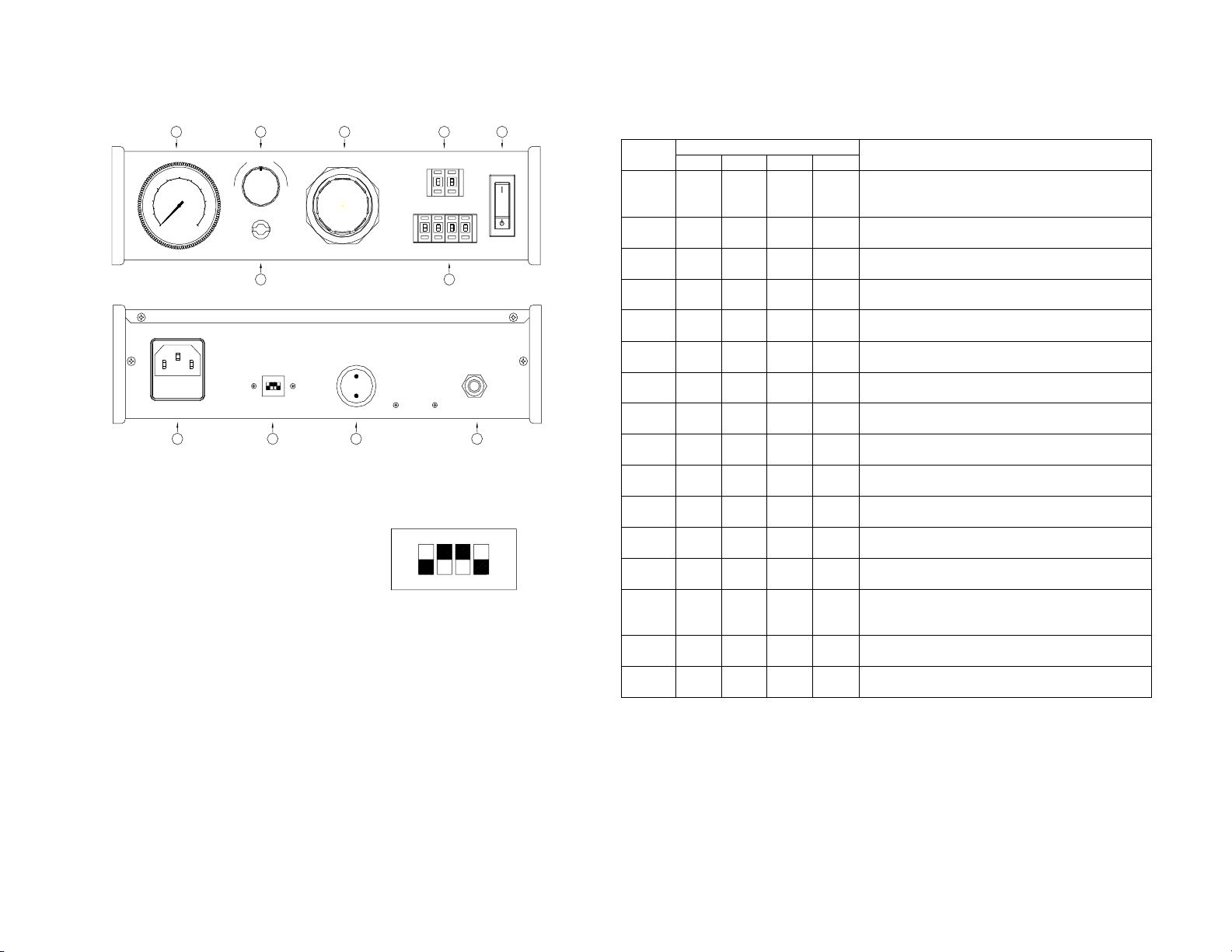
(2).Diagram of front and rear panels
0
10
2
0
30
40
50
60
70
80
90
100
0
1
2
3 4
5
6
7
VACUUM
+-
AI R PRESSUREINTERVAL
DISPENSINGTI ME
ON
OFF
FOOTSWIRTCH
SET UP
FUSE 0. 25
100 PSI MAX
0.7 MPa MAX
AIRIN
12345
67
10 9811
(3)Adjustment of dispensing time and interval
time
(a). Adjustment of dispensing time and interval time.
The dispensing time control button is located on the front panel of the unit.
The dispensing time can be set directly. Press the “+”button, and the
corresponding digit will increase by one. Similarly, press the “- ”button,
the corresponding digit will decrease by one. There are four digits in the
display, with a range from 0.01 second to 99.99 seconds, and the resolution
is 0.01 second.
(b). Interval Time Setup
The interval time control button is located on the front panel of the unit.
The interval time can be set directly. Press the “+”button will increase
the interval by one. Similarly, press the “- ”button will decrease the
interval by one. There are two digits in the display, with a range from 0.1
second to 9.9 seconds, and the resolution is 0.1 second.
Mode Switch Status
Item
No. S1 S2 S3 S4 Function
1 OFF OFF OFF OFF
With pedal switch pressed, dispense
continuously, otherwise it will
stop dispensing.
2 ON OFF OFF OFF Be triggered once, dispense at controlled time
once.
3 OFF ON OFF OFF
Be triggered once, dispense at controlled time
twice.
4 ON ON OFF OFF
Be triggered once, dispense at controlled time
three times.
5 OFF OFF ON OFF
Be triggered once, dispense at controlled time
four times.
6 ON OFF ON OFF
Be triggered once, dispense at controlled time
five times.
7 OFF ON ON OFF
Be triggered once, dispense at controlled time six
times.
8 ON ON ON OFF
Be triggered once, dispense at controlled time
seven times.
9 OFF OFF OFF ON Be triggered once, dispense at controlled time
eight times.
10 ON OFF OFF ON Be triggered once, dispense at controlled time
nine times.
11 OFF ON OFF ON Be triggered once, dispense at controlled time ten
times.
12 ON ON OFF ON Be triggered once, dispense at controlled time
eleven times.
13 OFF OFF ON ON Be triggered once, dispense at controlled time
twelve times.
14 ON OFF ON ON
Be triggered once, dispense at controlled time
continually, the next trigger will stop
dispensing.
15 OFF ON ON ON With pedal switch pressed, dispense at controlled
time continually, or it will stop dispensing.
16 ON ON ON ON Dispense at controlled time continually and
automatically.
Note: Dispensing at controlled time means dispensing according to set dispensing time
and interval time.
Mode switch on the rear panel of the unit
can be adjusted according to th
e
following table to suit different needs.
ON
12 43

(4)Internal air pressure control
The air pressure regulation knob controls internal air pressure. Air pressure
at 0.1-2.7bar (1-40Psi) is normally used.
(5)Vacuum control
The vacuum control knob regulates the ending dot in the air reflection, avoid connected
dots. Turn the knob clockwise will increase air reflection , otherwise, it will decrease.
(6)Set up
1. Connect the 7 bar dry and filtered air supply to the unit’s air input
plug.
2. Fill the barrel with syrup. Make sure the syrup level is not over the FULL
line,
(6)Operation
1. Turn the unit “on” by switching the red power to on position.
2. Pull the air pressure regulator knob outward and turn clockwise until the desired air
pressure is indicated.
3. Set the mode switch to proper position, referring to the adjustment of dispensing time
and interval time.
DISPENSOR
QUICK982B
FOOT SWITCH PL UG
BARREL ADAPTER ASSEMBL Y
POWER CORDBARREL STAND
AI R HOSE
COMPRESSED AI R
3. Helpful hints for making Proper deposit
1. Hold the barrel at approximately 60℃(+ or -20℃) angle(FIG1)
2. Lift the dispenser barrel vertically after making a drop, as shown (FIG2)
3. Do not let the syrup flow back into the controller as shown in FIG3.
4. Increase or decrease dot size by either,
Increase or decrease time only,
Or
Increase or decrease pressure only,
Or
Increase or decrease size of the tip.
60°
FIG.1 FIG.2
FIG.3
.

4. Cautions
1. The dispensed syrup maybe toxic and/or hazardous, refer to manufacturer’s
instructions for proper handling and safety precautions.
2. Compressed air pressure should not exceed 7 bar (100Psi). Otherwise, it will cause
negative effects (damage to objects or injury to the user).
3. Make certain air supply is clean and dry.
4. Syrup should be kept above 5℃to avoid change in density. Otherwise, the syrup
will be hard to dispense and proper dots can not be formed.
5. The air pressure should be regulated at 0.1-0.27Mpa (15-40Psi).
7. Clean the dispenser tip regularly.
8. The suck-back vacuum should be adjusted in conjunction with air pressure, dispensing
cycle and drop size. Too stronger vacuum will break the dispensed lines, cause running
back of the syrup through the controller, resulting in permanent damages to the unit.
9. Avoid turning barrels upside down or lay down on its side. Syrup may run through
air line to inside of the dispenser and cause component damages.
10. Avoid hit the plastic barrel assemblies with hot or sharp objects.
11. Avoid exposingthe dispenser to excessive moisture or solvent.
12. After use, clean the barrel and needles as soon as possible by soaking them in clean
water for 5-10 minutes.
3. The dispensing controller electrical schematic
1. Parts List
Symbol Description Part No.
F1 Fuse, 0.25Amp
P1 Potentionmeter 47087
P2 Controlling PCB 47166
S1 Solenoid Valve 26036
SW1 Power switch 12034
SW2 Foot pedal switch 47024
SW3 Time setup switch 12040
SW4 Mode Switch (DIP Switch) 47164
Transformer 110V/24V 18035
Transformer 220V/24V 18036
TR1
Transformer 230V/24V 18037
4. The dispensing controller pneumatic system.
1. Parts List
Symbol Description Part No.
1 Solenoid valve 26034
2 Dispensing socket 47165
3 Air pressure gauge 26035
4 Vacuum regulator 47163
5 Air pressure regulator 26036
6 Air-in manifold 44122
S1
P2
SW3
SW2
TI ME SETUP
BL ACK
BL ACK
BROWN
SW4
WHI T E
RED
BROWNBL CK
TR1
SW1
F1
BL UEBROWN
-
+
ON
+ -
P1
2 4 V AC
WHI T E WHI T E
PUSH WHEEL SWITCH
1. Electrical Theory Schematic
3
74
6
5
1
1.Theory Schematic of pneumatic system.

5. Trouble shooting
Problem Check or correction
No power 1.Check wall socket for power supply
2.Check fuse.
3.Unplug from wall. remove top cover ,visually inspect for
any loose or short connection.
Power on, but no light replace power switch
Power light on, does 1.Check foot switch connection.
not operate 2.Unplug from power supply, remove top cover and check for
loose connection.
Power light on, does 1.Check air supply and pressure gauge.
not dispense reset the regulator if necessary, remove barrel from
adapter .Depress foot switch to check air flow.
2.If solenoid clogged with foreign object from air compressor,
clean or replace it.
Solenoid buzzes 1.Voltage is too low
2.Air supply is insufficient.
3.Solenoid is not clean.
Burnt fuse 1.Checking fuse specifications.
2.Unplug power input, remove cover, and check internal
wiring for loose connection.
Inconsistent dots 1.Check needles tip, barrel, adapter and material for possible
clogging.
2.Check for air bubbles in the syrup.
3.Check air gauge for air pressure variation.
Dispensing ok, but 1.Check vacuum setting.
no vacuum in 2.Check air pressure setting(must be
dispense circuit 30-40Psi,0.2-0.27Mpa)
6. Parts list
No. Description Unit Quantity Part No.
1 Piston piece 1 25023
2 35cc barrel piece 1 25024
3 35cc adapter
(+1.0m clean tube) set 1 47089
4 Needle(10pieces/set) set 1 25025
CCC
USA
5 Power cable
VDE/CE
piece 1
6 Foot switch ( include two cores plug) set 1 47024
7 “O” ring piece 1 26041
8 Instruction manual set 1
9 Barrel rack piece 1 43035
10 Air-input tube (3m) set 1 26040
11 Adapter (match the barrel which cannot be
connected with the adapter) piece 1 42073
200-240V/0.25A piece12 Fuse 110V/0.5A piece
1
Table of contents