MadLab Bleep-o-tron User manual

Bleep-o-tron
Bleep-o-tron has the following features:
•polyphonic with 4 voices (4 notes can be played simultaneously)
•2 x oscillators (timbres) per voice
•8 x phase-modulation waveforms + combinations (36 in total)
•white noise
•6 x ADSR (attack-decay-sustain-release) envelopes per voice
•6 x LFOs (low-frequency oscillators) per voice
•6 x LFO waveforms (sine, square, triangle, rising sawtooth, falling sawtooth, noise)
•detuned oscillators by semitones or cents
•connects to standard MIDI keyboards (velocity sensitive)
•keyboard transpose (up to +/–2 octaves)
•keyboard split
•pitch bend and modulation
•ring modulator
•oscillator synch
•flanger (swept comb filter)
•portamento (constant rate and constant time)
•delay line (up to 150ms) with feedback and dry-wet mix
•selectable MIDI channel #1 to #16 or all channels
•40 x preset patches
•24 x user patches (non-volatile)
•master volume control
•Windows desktop app Patch Editor
The Patch Editor is located in the repository below. A single zip file contains the executable and associated
DLL. Simply unzip to a directory on your machine, no installer needed.
www.github.com/clubmadlab/Bleep-o-tron/
Web: www.madlab.org
Twitter: @clubmadlab

Construction
First fit and solder the resistors (R1 to R9) to the circuit board and trim their legs. Identify the resistors by the
coloured stripes on the body.
Next fit the chip sockets (IC1, IC2 and IC3) matching the notch in the socket against the notch in the symbol
on the board. Care should be taken when soldering these components to avoid solder bridges between the
pins. It is not recommended that the chips are soldered directly to the board.
Solder the ferrite bead (FERRITE) either way around. (Be careful not to mistake the diode D1 for the ferrite,
the diode has a stripe at one end of the body.)
Solder the diodes (D1 and D2) matching the stripe at one end to the stripe (also marked ‘k’) on the board.
Solder the pushbuttons (S1 - S4) to the board.
Fit and solder the capacitors, paying attention to the polarity of the electrolytics (C1, C2, C3 and C4)
(negative is marked by a stripe on the side of the body). The tantalum capacitor (C5) should be fitted such
that the shorter leg is by the minus sign. The ceramic capacitors (C6, C7, C8, C9 and C11) and the polyester
capacitor (C10) can be fitted either way around.
Bend the legs of the regulator (REG1) at right angles and solder it such that the metal heatsink is flat on the
board and the side with the writing is facing upwards.
Solder the LED (LED1) matching the shorter leg (also flat on the rim) to the hole with the line.
Solder the transistor (TR1) matching the shape to the symbol on the board.
Solder the jack socket (AUDIO) and the DIN socket (MIDI).
Solder the power socket (POWER), or alternatively the PP3 battery snap, to the board. If the latter, support
holes are drilled on the board for the battery snap leads. Feed the leads up through the support holes from
the rear side of the board and then down the solder holes. Red is positive and black is negative.
Don't fit the chips into their sockets until you have thoroughly checked your construction. Check that all the
components have been inserted correctly and that there are no dry joints and no solder bridges between
pins. Then match the small notch in each chip, or dot in one corner, to the notch in its socket. (Be careful not
to mix up the two 8-pin chips.)
Attach rubber feet to the underside of the board at the corners.
Connect headphones or powered speakers (with a 3.5mm jack plug) to the audio output socket and a MIDI
keyboard to the MIDI socket using a standard 5-pin DIN MIDI cable.
Either connect a mains power supply (6-9V regulated DC, 300mA, centre +) to the power socket, or 4 AA cells
to the battery snap.
The software includes a power-on self-test. The LED should flash twice if the board is functioning correctly.
Bleep-o-tron can output an audio signal on its jack socket which has a maximum peak-to-peak of about 2
volts. This is more than capable of producing a loud sound in a pair of 32-ohm impedance headphones.

How to use
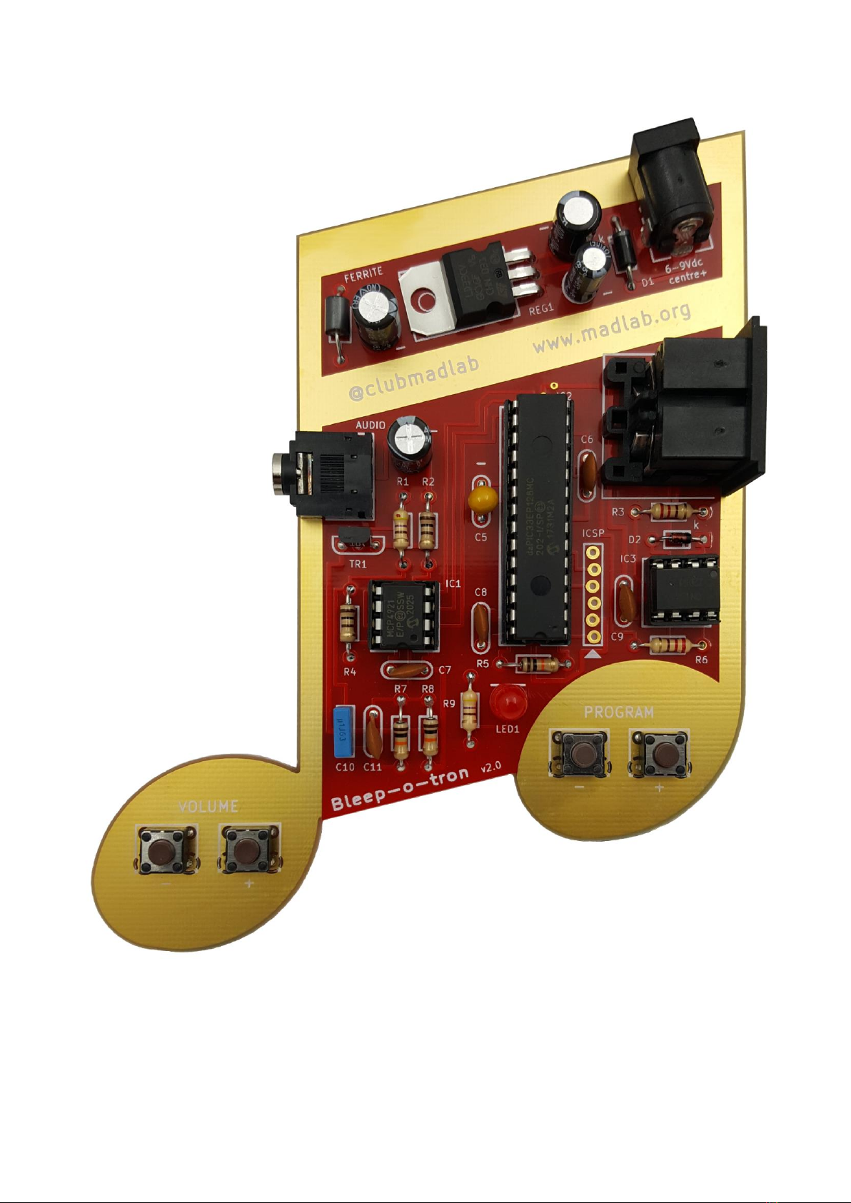
The preset and user patches can be accessed using the pushbuttons on the PCB marked PROGRAM. New
patches can be created and stored in the dsPIC chip using a Windows desktop Patch Editor app. Typically this
works in conjunction with a USB-to-MIDI adapter connected to the PC and the MIDI socket on Bleep-o-tron.
(Note that the USB-to-MIDI adapter must be able to handle MIDI SysEx messages correctly for the Patch
Editor to work.)
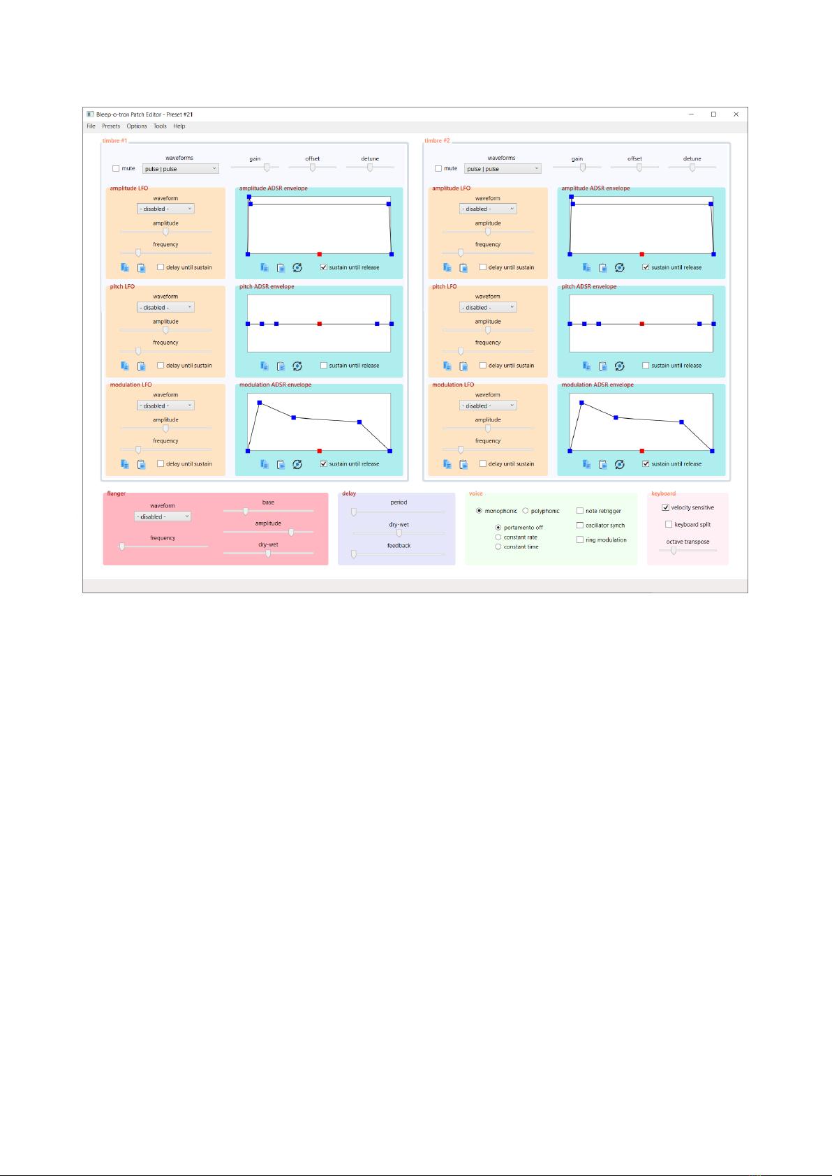
The fundamental sound generators of Bleep-o-tron are a pair of oscillators or ‘timbres’. Different waveforms
are available for each of these oscillators and they can be combined to produce more complex sounds. In
addition, each oscillator can output white noise.
The amplitude (volume) and pitch (frequency) of each timbre oscillator is under the dynamic control of both
an envelope and a low-frequency oscillator. The modulation (the degree to which the oscillator outputs a
simple sine wave or a more complex waveform) is also controllable by the same means. (Modulation is
equivalent to low-pass filtering in a traditional analogue synthesiser.)
The second oscillator can be detuned or offset relative to the first. This can be used to further ‘thicken’ a
sound. Detuning can be done by fractions of a semitone (known as ‘cents’), and can cause tremolo-type
effects as the two oscillators move into and out of phase with each other. Offsetting by a whole number of
semitones is equivalent to a two-note chord. Some intervals are very discordant. Whole octave intervals can
add body to a sound.
The gain or amplitude of each timbre can be independently adjusted. This is useful for making one
component of a sound dominant relative to the other. The default timbre gain is ¾ of the maximum.
Classic four-stage attack-decay-sustain-release envelopes are available for both oscillators to control their
amplitude, pitch and modulation. The level and period of the four stages can be individually adjusted for all
six envelopes, and envelopes can be sustained for as long as a key is held down.
An envelope can be copied to another and reset to the defaults.
Low-frequency oscillators, or LFOs, allow effects such as tremolo and vibrato. The amplitude, frequency and
waveform of each LFO can be independently controlled. Six LFO waveforms are available - sine, square,
triangle, rising sawtooth, falling sawtooth and noise. There is an option to delay an LFO until the sustain
period of its associated envelope.
One LFO can be copied to another.
Portamento is available which causes a glide between pitches when two notes are pressed in succession (as
opposed to the normal discrete jump from one pitch to the other). There are two types of portamento -
constant rate which means that small spans on the keyboard are covered more quickly than longer spans,
and constant time which means that glides take the same amount of time irrespective of the span length.
‘Retrigger’ causes all envelopes and LFOs to be restarted when a second note is pressed before a first has
finished playing. It can result in glitches when notes are pressed in quick succession so is not normally used,
but might be useful in certain circumstances.
A flanger is available which acts as a dynamic filter removing a set of regularly-spaced frequencies from the
sound spectrum (i.e., a comb filter). The position of the filter notches is under the control of a separate LFO,
and the range, waveform, speed of frequency sweep and dry-wet mix are all controllable. (The flanger is
implemented as a variable-length delay line and its parameters affect the instantaneous length of the delay

line.) The sound of the flanger is hard to describe but there are several built-in patches that demonstrate its
use.
A ring modulator is available which produces bell-like sounds rich in inharmonic partials.
‘Oscillator synch’ is a technique for locking the two timbre waveforms, causing timbre #2 to be restarted
when timbre #1 cycles.
There is an additional delay line that is shared by all voices. The delay period, feedback level and dry-wet mix
can be controlled.
A collection of settings (waveforms, LFOs, envelopes etc.) making a particular sound is known as a program
or ‘patch’ (from the days when synthesisers were controlled by patch leads and plug boards). There are a
number of patches built in to Bleep-o-tron which can be selected using the pushbuttons on the board
marked PROGRAM. There are also a number of user patches that can store sounds of your own. These user
patches are retained when power is removed from the board.
Bleep-o-tron connects to standard MIDI equipment such as a keyboard or sequencer. (Note that there is no
MIDI THRU socket.) Patches can be selected using the program change buttons on the keyboard, and
keyboard pitch and modulation wheels are supported. A specific MIDI channel can be selected causing
Bleep-o-tron to ignore MIDI notes and commands sent on other channels, or it can be set to disregard MIDI
channel information altogether and respond to notes and commands on all channels. The default behaviour
is to respond to MIDI channel #1. The default channel can be changed to a different channel using the Patch
Editor, or set to respond to all channels. Note that if you inadvertently set the channel to a different channel
to your keyboard then pressing two pushbuttons simultaneously on Bleep-o-tron sets it to respond to all
channels.
MIDI velocity (volume) data is supported, or it can be ignored causing all notes to sound at maximum
volume. The MIDI keyboard can also be split into two halves (at the note middle C or C4) causing timbre #1
to sound when notes below C4 are pressed and timbre #2 to sound when notes above C4 are pressed.
There is a master volume control using the pushbuttons on the board marked VOLUME. Don’t set the
volume too high when using headphones.
An option in the Patch Editor allows the default MIDI channel, default MIDI program and initial volume to be
stored in non-volatile memory in Bleep-o-tron.


Component list
Resistors
R1, R9 470R (yellow, purple, brown, gold)
R2, R4 100R (brown, black, brown, gold)
R3, R6 220R (red, red, brown, gold)
R5, R7, R8 10k (brown, black, orange, gold)
Capacitors
C1, C4 220uF electrolytic (blue or black)
C2 100uF electrolytic (blue or black)
C3 10uF electrolytic (blue or black)
C5 10uF tantalum (yellow/brown, beaded)
C6, C7, C8, C9, C11 100nF ceramic (brown, marked ‘104’)
C10 100nF polyester (yellow or blue, square)
Semiconductors
TR1 ZTX689B transistor (black)
REG1 LD1117V33 LDO 3.3V 0.8A regulator (black/silver)
D1 1N4001 diode (black with silver stripe)
D2 1N4148 diode (orange with black stripe)
LED1 5mm red
IC1 MCP4921 12-bit DAC + 8-pin socket
IC2 dsPIC33EP128MC202 microcontroller + 28-pin socket
IC3 6N138 opto-isolator + 8-pin socket
Miscellaneous
FERRITE ferrite bead (black)
AUDIO 3.5mm jack socket
MIDI 5-pin DIN socket
S1 - S4 miniature tactile pushbutton
POWER 2.1mm dc power socket
PP3 moulded battery snap + 4 x AA battery box
PCB
Self-adhesive rubber feet x 4
Design and documentation © MadLab Ltd. 2022
Table of contents
Other MadLab Recording Equipment manuals