C1
(10u)
Battery
snap www.madlab.org
©MadLab®2017
FUNKY DRUMMER
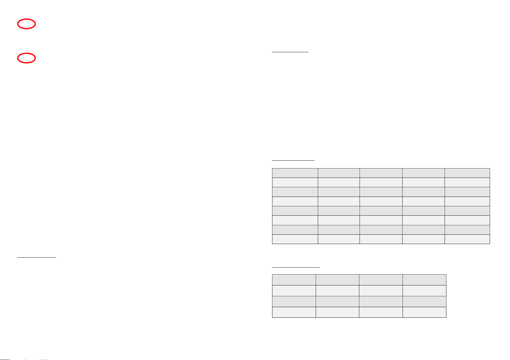
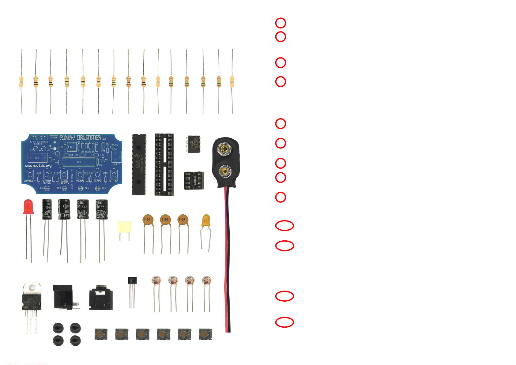
Identify the different components using the spotter chart.
1
Fit and solder all the resistors (R1 to R15) to the circuit board. Identify the
resistors by the coloured stripes on the body. They can be fitted either way
around.
2
Solder the light-dependent resistors (LDR1 to LDR4). Be careful with
these components as excessive heat can melt the plastic.
5
Solder the chip sockets (IC1 and IC2) matching the notch in the socket to
the notch on the board. Do not solder the chips directly to the board.
3
Solder the pushbuttons (S1 to S6) either way around.
7
Solder the transistor (TR1) matching the half-circle shape of the transistor
to the half-circle shape on the board.
8
Fit and solder the electrolytic capacitors (C1, C2, C3 and C8) to the board
putting the shorter leg into the hole with the – sign. The shorter leg also
has a stripe on the side of the body. Also solder the tantalum capacitor
(C6) so that the shorter leg is by the – sign. Fit and solder the remaining
ceramic (C4, C5 and C9) and polyester (C7) capacitors either way around.
4
Solder the jack socket (AUDIO), first cutting off the five small plastic
lugs on the underside so it fits flush on the board.
10
Bend the legs of the regulator (REG) at right angles and solder it such
that the metal heatsink is flat on the board and the side with the writing
is facing upwards.
9
programmable rhythm machine with 40 drum sounds
MLP114 1/7/17
REG
(LD33V)
IC2 socket
continued overleaf
Solder the light (LED) to the board putting the shorter leg into the hole
with the line. The shorter leg also has a flattened edge on the rim.
6
IC2
(dsPIC33F)
R9
(10k)
(brown, black, orange, gold)
R1
(0R)
(black)
R15
(0R)
(black)
R10
(0R)
(black)
R4
(100R)
(brown, black, brown, gold)
R2
(10k)
(brown, black, orange, gold)
R3
(10k)
(brown, black, orange, gold)
R8
(1R)
(brown, black, gold, gold)
R11
(150k)
(brown, green, yellow, gold)
R12
(150k)
(brown, green, yellow, gold)
R13
(150k)
(brown, green, yellow, gold)
R14
(150k)
(brown, green, yellow, gold)
R5
(470R)
(yellow, purple, brown, gold)
R6
(47R)
(yellow, purple, black, gold)
R7
(150R)
(brown, green, brown, gold)
C8
(220u)
C3
(220u)
C7
(100n)
Jack socket
IC1 socket
IC1
(MCP4921)
LED
(red)
LDR1 LDR2 LDR3 LDR4
TR1
(ZTX689B)
11 Solder the power socket (POWER). Optionally also fit the PP3 battery
snap (BATTERY). Push the battery snap leads up through the larger
holes in the board from the metal side of the board. Fit the metal tip of
the red lead into the BATT + hole and the metal tip of the black lead
into the BATT – hole. Solder the metal tips to the tracks on the board
then pull the wire loops back.
C2
(100u)
Power socket
C6
(10u)
S2S1 S3 S4 S5 S6
C9
(100n)
C4
(100n)
C5
(100n)
Carefully bend the legs of the chips inwards a little with your fingers.
Fit the chips into their sockets matching the small notch in the chip to
the notch in the socket.
12
Attach rubber feet to the corners of the board.
13