AudioArts Engineering R-5 User manual

R-
5
Audio Console
OWNER'SMANUAL
March 1997

AUDIOARTS ENGINEERING
600 Industrial Drive
New Bern, North Carolina 28562
252-638-7000 (Fax 252-637-1285)
Email: email@wheatstone.com
R-5 Audio Console Technical Manual — revised 3/97
©1997 Audioarts®Engineering
(a division of Wheatstone Corporation)
R-5 / June 98

R-5 / Jan 97 Contents - i
Table of Contents
FIRST STEPS / BASIC INFO
Unpacking the Console ................................................................1-2
Mainframe Installation .................................................................1-2
System Ground.............................................................................1-3
Console Power Supply..................................................................1-5
Energizing the Console................................................................1-5
Wiring Overview ............................................................................1-6
Individual Channel I/O Connectors..............................................1-7
Balanced vs Unbalanced Connections.........................................1-8
Wiring Up the Console .................................................................1-9
Set-up and Test.............................................................................1-9
Technical Documentation............................................................1-9
Drawing – Console Controls and I/O Connectors......................1-10
Console System Signal Flow Diagram .......................................1-11
Performance Specifications .......................................................1-12
MONO MIC INPUTS
Overview........................................................................................2-2
Signal Flow Diagram.....................................................................2-2
Controls and Features..................................................................2-3
Mono Mic Input Channel Wiring ..................................................2-4
Audio Connections.......................................................................2-4
Logic and Control Wiring .............................................................2-5
Drawing – Typical Remote Logic/Control Hook-ups ...................2-6
Technical Documentation............................................................2-7
STEREO LINE INPUTS
Overview........................................................................................3-2
Signal Flow Diagram.....................................................................3-2
Controls and Features..................................................................3-3
Stereo Line Input Channel Wiring ...............................................3-4
Audio Connections.......................................................................3-4
Logic and Control Wiring .............................................................3-5
Drawing – Typical Remote Control Hook-ups .............................3-6
Technical Documents ..................................................................3-7
R-5 / Mar 97R-5 / Aug 00

R-5 / Jan 97 Contents - ii
CONTENTS
TELEPHONE INPUT
Overview........................................................................................4-2
Signal Flow Diagram.....................................................................4-2
Controls and Features..................................................................4-3
Wiring – Audio Connections ........................................................4-4
Technical Documentation............................................................4-5
OUTPUTS
Overview........................................................................................5-2
Controls and Features..................................................................5-2
Signal Flow Diagram.....................................................................5-3
Output Wiring ...............................................................................5-4
Technical Documentation............................................................5-5
MONITORS
Overview........................................................................................6-2
Signal Flow Diagram.....................................................................6-3
Controls and Features..................................................................6-4
Monitor Circuit Wiring .................................................................6-5
Audio Connections.......................................................................6-5
Control Wiring ..............................................................................6-6
Technical Documentation............................................................6-7
ACCESSORIES
Overview........................................................................................7-2
Signal Flow Diagram.....................................................................7-2
Controls and Features..................................................................7-3
Accessory Wiring..........................................................................7-4
Tape Remote Switches (Control) .................................................7-4
Line Selector (Audio) ...................................................................7-5
Technical Documentation............................................................7-6

R-5 / Jan 97 Contents - iii
SET-UP AND TEST
Factory Calibration.......................................................................8-2
End-User Set-up and Test ............................................................8-2
Mono Mic Inputs...........................................................................8-2
Stereo Line Inputs........................................................................8-3
Telephone Input ...........................................................................8-5
Outputs .........................................................................................8-6
Monitors (Audio)...........................................................................8-6
Monitors (Control)........................................................................8-7
Talkback .......................................................................................8-8
Tape Remote .................................................................................8-8
Timer.............................................................................................8-8
Line Selector ................................................................................8-9
TECHNICAL DOCUMENTATION
MB-5 mother board schematic.....................................................9-2
MB-5 circuit card dwg.................................................................9-12
MB-5 parts list ............................................................................9-13
OM-5 output board schematic....................................................9-15
OM-5 circuit card dwg ................................................................9-21
OM-5 parts list ............................................................................9-22
SW-R5 circuit card dwg ..............................................................9-25
SW-R5 parts list..........................................................................9-26
Console parts list .......................................................................9-27
Mainframe parts list ...................................................................9-28
APPENDIX
External On Tally Circuit ............................................................ A-2
External Headphone Pad Circuit ................................................ A-2
Monitor Level Settings ................................................................ A-3
Pad Circuit for +4dBu Console Outputs ..................................... A-3
Disabling Phantom Power........................................................... A-4
Hand Crimp Tool Wiring Instructions ........................................ A-5
Extractor Pin Tool Instructions.................................................. A-6
Insert Point Bridging Resistors .................................................. A-7
Denon DN-951 Cd Player Hook-up Diagram ............................... A-8
Studio Dimming Resistors .......................................................... A-9
R-5 / Oct 99

Page 1 - 1
R-5 / Jan 97
FIRST STEPS/BASIC INFO
First Steps/Basic Info
Chapter Contents:
Unpacking the Console ....................................................................... 1-2
Mainframe Installation ........................................................................ 1-2
System Ground.................................................................................... 1-3
Console Power Supply ........................................................................ 1-5
Energizing the Console....................................................................... 1-5
Wiring Overview................................................................................... 1-6
Individual Channel I/O Connectors .................................................... 1-7
Balanced vs Unbalanced Connections................................................ 1-8
Wiring Up the Console ........................................................................ 1-9
Set-up and Test ................................................................................... 1-9
Technical Documentation................................................................... 1-9
Drawing – Console Controls and I/O Connectors............................. 1-10
Console System Signal Flow Diagram .............................................. 1-11
Performance Specifications .............................................................. 1-12
PROGRA
M
AUDITION
10"10"
30.3"
31 3/8"
5"
6 1/2"
21 1/2"
#8
woodscre
w
(t
y
p 4)
R-5 / Aug 00

Page 1 - 2
R-5 / Jan 97
FIRST STEPS/BASIC INFO
UNPACKING THE CONSOLE
The console is shipped as two packages. One (larger) carton contains the
console and technical documentation; the other (smaller) contains the
rackmount power supply, connecting cable, and connector kit.
MAINFRAME INSTALLATION
DO NOT CONNECT THE R-5 CONSOLE TO ITS POWER SUPPLY, AND DO
NOT CONNECT THE POWER SUPPLY TO THE AC POWER LINE UNTIL
INSTRUCTED TO DO SO.
It is not necessary to prepare the counter by making a cutout, since the
R-5 is mounted above the counter top. If you will be securing the console
to a counter top, you will need to drill mounting holes for four #8
woodscrews as shown in the drawing below.
PROGRAM AUDITIO
N
10"10"
30.3"
31 3/8"
5"
6 1/2"
21 1/2"
#8
woodscrew
(t
y
p 4)
Pre-drillfor#8woodscrews—doNOTuselargerdiameterscrews;theymaysplittheconsolewood!
Drill COUNTERTOP with .173" diameter (#17 drill) clear holes. Pre-drill CONSOLE WOODEN
ENDPIECES from below with .136" diameter (#29 drill) tap holes. Use hole locations as shown.
Attach the console mainframe to the counter top by screwing up through
the counter into the tap holes you have drilled into the bottom of the
mainframe's left and right wooden end pieces (two per side).
R-5 / Sep 02

Page 1 - 3
R-5 / Jan 97
FIRST STEPS/BASIC INFO
The first step is to ground the console.
SYSTEM GROUND
While console power supply common, audio common, and the
mainframe chassis are connected together at the R-5 mainframe, they
are not connected to electrical ground and the chassis of the power
supply.Safetyrequirementsdictate thatapositiveconnectionfrom the
console mainframe to electrical ground be made in the completed
installation; audio requirements also dictate this same connection—
use the two grounding lugs on the connector surface area of the
mainframe(underneaththehingedmeterbridge)toestablishyoursystem
ground (see left AUD VU meter area on drawing on page 1-1).
The system ground serves two important purposes:
(1) Provides a zero signal reference point for the entire audio system;
(2) Assures safety from electrical shock.
There exist two terms that one encounters in a discussion of ground:
(A) EARTH GROUND, which is usually a heavy copper rod driven
into the soil adjacent to the building (around 6 feet down) or
a connection to the copper water pipes leading into the
building. Either is acceptable (unless, of course, the water
pipes are plastic).
(B) THE POWER COMPANY EARTH CONDUCTOR that enters the
buildingatthepower line breaker box; this conductorshould
be (and is often by code) tied to the above-mentioned earth
ground at one point. This point is the SYSTEM EARTH
GROUND.
TIE THE CONSOLE GROUND LUG TERMINALS TO THE SYSTEM
EARTH GROUND. TIE EVERY PIECE OF EQUIPMENT IN THE ENTIRE
AUDIO SYSTEM TO THE CONSOLE'S GROUND LUG TERMINALS. If the
system earth ground point is inaccessible, tie the console ground
terminalstothepowercompanyearthconductoratthemainbreakerbox
(see drawing "Typical Grounding Scheme" on page 1-4).
Each piece of equipment should be connected by its own ground wire
(usually the round third pin on the AC cord). This means that every AC
outlet must have a separate conductor run to the console ground lug
terminals;theoutletscannotbedaisy-chainedasisnormallyencountered
in commercial and residential AC systems. Any equipment not supplied
with 3-wire AC cables must have individual ground wires (16 gauge or
larger) connected to their chassis grounds and then run to the console
ground lug terminals.

Page 1 - 4
R-5 / Jan 97
FIRST STEPS/BASIC INFO
Tie the console's ground lug
terminals to the system earth
ground. Tie every piece of
equipment in the entire audio
system to the console ground
lug terminals.
CONSOLE
2-TRACK
MULTI-TRACK
AC BREAKER
BOX
DEVICE 1
DEVICE 2
DEVICE N
CONSOLE POWER SUPPLY
CONTROL ROOM POWER AMP
STUDIO POWER AMP
OTHER
POWER COMPANY
EARTH GROUND
HEAVY
(#4 or #6)
COPPER
WIRE
HIGH POWER
EQUIPMENT RACK
COPPER ROD
SOIL
3-wire ground or separate wire run from chassis
EFFECTS RACK
MIC PANEL
GND
TYPICAL SYSTEM
GROUNDING SCHEME
etc.
3–5 ft.
Further Grounding Details
Check all equipment to be absolutely certain that each unit is power
transformer isolated from the AC mains to prevent safety hazards.
It is assumed that in each piece of audio equipment the audio ground
and the chassis are tied together at some point. Any piece of equipment
lackingagroundedchassisislikelytobepronetointerferenceproblems.
Locate all unbalanced audio equipment in the same rack if possible, to
minimize chassis ground potential differences. It may also be helpful to
insulate each piece of unbalanced equipment from it’s mounting rails in
therack bymeans of nylon 10-32 screws and insulating washers between
rails and faceplates.
As a rule of thumb, consumer
units (low level, –10dBu,
unbalanced) usually utilize RCA
jacks and two conductor wiring
connections; professional level
equipment (+4dBu, balanced)
generally uses three-conductor
XLR connectors.

Page 1 - 5
R-5 / Jan 97
FIRST STEPS/BASIC INFO
The next step is to install the rackmount power supply.
THE CONSOLE POWER SUPPLY
The R-5 console uses a separate rackmount power supply unit. The
power supply should be mounted in an adjacent equipment rack within
fifteen feet (but no closer than 3 feet) of the console. It should be
mounted in a rack space (it requires two rack spaces or 3-1/2") where
properaircirculationispossible.Avoidlocatinganyhighgainequipment
(suchasphonopreamps,taperecorders,etc.)toonearthepowersupply,
to avoid magnetic interference into that equipment.
Once the supply is mounted, connect the linking power cable at the
console end; the connector is a 6-pin plug that mates with a matching
socket("DCIN")mountedontheconsoleconnectorareaunderneaththe
righthand end of the hinged meterbridge (see drawing page 1-10).
Connect the other end of the cable to the rear of the rackmounted power
supply.
The power supply is fitted with a 3-wire grounded AC cord that should
be plugged into a “clean” AC power source. That is, an AC source that
feedsonlythecontrolroomaudiogear. Thissourceshouldbeaseparate
feed from those powering lighting, air-conditioning, or any other non-
audio machinery. The third pin ground wire of the AC source should be
tied to the system earth ground point (see “System Ground” section).
Note that while the AC power cord ground wire terminates at the power
supply chassis, it does NOT connect to the R-5 console common; the
console itself must be grounded separately. (See previous section:
“System Ground”.)
ENERGIZING THE CONSOLE
Assuming the console mainframe is properly installed and grounded,
and its power supply correctly rackmounted and connected to the
console,youmaynowenergizetherackmountpowersupplybyplugging
it into the AC mains.
The four LEDs on the power supply front panel should light up to
indicate the presence of their respective voltages. The console's VU
meters and timer display will illuminate. All other switches should
alternateonandoffwhenpressedinsuccession.(NoteCUEswitcheswill
de-activate when an associated line input red channel ON switch is
pressed. Amber channel OFF switches should deactivate ON switches
when pressed.
Once you have verified proper power-up, unplug the rackmount
power supply to de-energize the console.
You are now ready to proceed with audio and control wiring. First,
however, you should familiarize yourself with the R-5 wiring system
and supplied tools (next section).
The power feed recommended
in the text is often installed and
referred to in studios as an “iso-
lated AC ground” outlet.
It is usually orange in color.

Page 1 - 6
R-5 / Jan 97
FIRST STEPS/BASIC INFO
WIRINGOVERVIEW
Allaudio/controlconnectionsandend-userprogrammingofR-5console
functions take place at 12-pin AMP-type connectors located along the top
of the console, directly underneath the hinged meterbridge (see top of
drawing on page 1-1). Each connector consists of a printed-circuit board
("PCB") mounted female socket and a supplied mating male plug.
All R-5 console wiring takes
place at the top of the
console, underneath the
hinged meterbridge.
A connector kit is included with each console, and consists of mating
plugs, a crimp tool (Paladin model PA1645), an appropriate number of
crimp type wiring pins (.062" pin diameter; to be used with 22 gauge wire)
and a pin extractor tool (used to remove crimp pins that have been
accidentally inserted in the wrong connector block hole, or if rewiring or
wiring repair is needed).
Thesuppliedcrimptool(withextractorpin)isused
to wire up all I/O connector plugs.
Close-up of a wired-up 12-pin I/O connector plug
being inserted into its PCB-mounted socket.
R-5 / Apr 00

Page 1 - 7
R-5 / Jan 97
FIRST STEPS/BASIC INFO
R-5 console typical 12-pin connector socket.
I/O connector plug (rear
view). The beveled corners
in the key diagram to the
rightcorrespondtotheplug's
matingPCB-mountedsocket
(shown above).
3
6
9
12
2
5
8
11
1
4
7
10
3
6
9
12
2
5
8
11
1
4
7
10
Individual Channel I/O Connectors
Console input channels each have two 12-pin connectors: UPPER (for
LOGIC and control) and LOWER (for AUDIO). Note that audio signal
connections follow a logical pattern: They are grouped in 4 sets of 3 pins
each (1-3, 4-6, 7-9, and 10-12). The first pin of each group (1, 4, 7, and 10)
is audio common (ground) for connection of shields. The next pin (2, 5, 8,
and 11) is the low side for balanced signals, or ground for unbalanced
signals. The third pin (3, 6, 9, and 12) is the high side for balanced signals,
or the signal connection for unbalanced ones.
Thepinorientationshownbelowisidenticaltowhatyouwouldseewhen
looking at the BACK of a mating 12-pin plug while performing wiring:
Instructions for the use of the supplied crimp tool and extractor pin are
printed on each tool's packaging. Duplicate copies of this information are
also reproduced in the Appendix of this manual (see pages A-5 thru A-6).
The audio signal pattern described
in the text applies to input channel
AUDIO (lower) connectors. Logic,
output, monitor and accessory
connectors have their own pinouts.
See appropriate manual chapters
fordetailedinformation.Inallcases,
however,thepinnumbering pattern
(1-12) is identical.
R-5 / Mar 97
Page 1 - 8
R-5 / Jan 97
FIRST STEPS/BASIC INFO
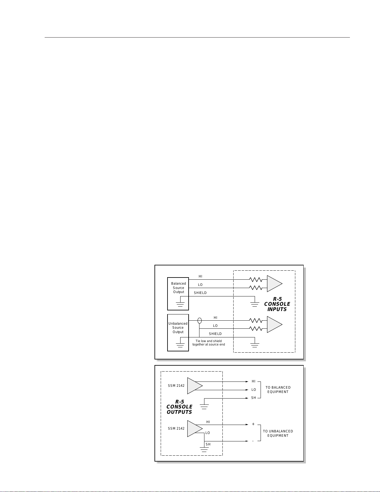
BALANCED vs UNBALANCED CONNECTIONS
Bynoweveryoneknows(orshouldknow)thatbalancedinputsandoutputsare
highly desirable —they have an intrinsic ability to reject hum, noise, crosstalk,
and RF, even if the shielding and grounding leave something to be desired. The
R-5 console has electronically balanced inputs and outputs, and leaves the
factory ready to accept professional level, +4dBu balanced source signals.
Not all equipment used in stations is balanced, however, and the most cost-
effective devices often don’t have +4 dBu output levels, either. Because of these
realities, the R-5 console is designed to accept balanced or unbalanced sources
withlevelsaslow as -10dBu. Ifyouwillbe using this typeofequipment,be aware
that line input gain for affected channels should be reprogrammed for low level
–10dBu signals (see bottom of page 3-4 and top of page 3-5).
Connecting unbalanced inputs is simple—wire to the console with typical
shielded two conductor cable (like Belden 9451), just as if you were connecting
a balanced source. At the unbalanced machine’s output, connect the black wire
(LOW) to the shield. This “pseudo-balanced” connection has proven to be the
simplest and most trouble-free way to go. Another plus is that the wiring need
notbechangedoutifabalancedoutputmachineissubsequentlyinstalledinthat
position.
If you will be connecting console OUTPUTS to an unbalanced system, be sure
to connect the LOW side and SHIELD together at the console, and connect the
unbalanced system to the HIGH side output and LOW/SHIELD connections.
The diagrams below summarize these connections:
HI
LO
SHIELD
HI
LO
SHIELD
Balanced
Source
Output
Unbalanced
Source
Output
R-5
CONSOLE
INPUTS
Tie low and shield
together at source end
SSM 2142 HI
LO
SH
TO BALANCED
EQUIPMENT
SSM 2142
HI
LO
SH
+
–
R-5
CONSOLE
OUTPUTS
TO UNBALANCED
EQUIPMENT
As a rule of thumb,
consumer units (low
level,–10dBu,unbalanc-
ed) usually utilize RCA
jacks and two conductor
wiring connections;
professionallevelequip-
ment (+4dBu, balanced)
generally uses three-
conductor XLR con-
nectors.
R-5 / Mar 97

Page 1 - 9
R-5 / Jan 97
FIRST STEPS/BASIC INFO
WIRING UP THE CONSOLE
With the console mainframe installed and properly grounded, and the
rackmount power supply installed, connected, and console power-up
verified, you are now ready to proceed with audio and control wiring.
Note the main portion of this manual is organized by channel type
(inputs, outputs, monitors and accessories). Each chapter has a special
section devoted to wiring hook-ups; use the information in these sections
(typically called "Audio Connections" and "Logic and Control Wiring") to
proceed.
Specific Wiring Instructions: Page
Mono Mic Inputs......................................................... 2-4
Stereo Line Inputs...................................................... 3-4
Telephone Input ......................................................... 4-4
Outputs....................................................................... 5-4
Monitors ..................................................................... 6-5
Accessories ................................................................ 7-4
SET-UPAND TEST
Onceallwiringiscomplete,ascalledoutintheinstructionslistedabove,
proceed to Chapter 8 ("Set-up and Test") which will walk you through a
check-out procedure for your R-5 console.
TECHNICALDOCUMENTATION
Technical documentation and drawings (schematics, printed circuit
board pictorials and load sheets, parts lists) are contained in Chapter 9.
R-5 / Aug 00
10 9
8
7
64
3
2
10
5
CUE
10 9
8
7
64
3
2
10
5
HDPN
10 9
8
7
64
3
2
10
5
CR
10 9
8
7
64
3
2
10
5
STUDIO
PGM
AUD
CALLER
UTPUTO
TRIMTEL
HDPN
AMIC 2 B
GAIN
TRIM
MIC 1
A B
GAIN
TRIM
OUTPUT TRIMS
PGM AUD VU TRIMS
PGM AUD
DC IN
LOGIC
AUDIO
PGM / AUD OUT
PHONE / TEL
/O B LINE / HDPN OUT
CUE / TALLY
TIMER
CUE
ASSIGN
A
B
PGM
AUD
TEL
INPUT
CUE
ASSIGN
GND GND
TAPE I
/O ATAPE I
1/2 3 /4LINE EXT 1-2 STUCR-
/
PLAY
REC
STOP
REW
FF
RTZ
S/S
RST
HOLD PGM
AUD
TEL
EXT 2
EXT 1
TB
3
4
5
2
1
6
T
I
M
E
R
T
A
P
E
L
I
N
E
S
O
U
R
C
E
S
E
L
E
C
T
TRIM
L R L R L R L R
LINE 5 /6
0
5
10
15
20
30
40
50
00
0
5
10
15
20
30
40
50
00
CUE
ASSIGN
A
B
PGM
AUD
TEL
INPUT
0
5
10
15
20
30
40
50
00
CUE
ASSIGN
A
B
PGM
AUD
TEL
INPUT
0
5
10
15
20
30
40
50
00
CUE
ASSIGN
A
B
PGM
AUD
TEL
INPUT
0
5
10
15
20
30
40
50
00
CUE
ASSIGN
A
B
PGM
AUD
TEL
INPUT
0
5
10
15
20
30
40
50
00
CUE
ASSIGN
A
B
PGM
AUD
TEL
INPUT
0
5
10
15
20
30
40
50
00
CUE
ASSIGN
A
B
PGM
AUD
TEL
INPUT
0
5
10
15
20
30
40
50
00
CUE
ASSIGN
A
B
PGM
AUD
TEL
INPUT
0
5
10
15
20
30
40
50
00
CUE
ASSIGN
A
B
PGM
AUD
TEL
INPUT
0
5
10
15
20
30
40
50
00
CUE
ASSIGN
A
B
PGM
AUD
TEL
INPUT
0
5
10
15
20
30
40
50
00
ASSIGN
A
B
PGM
AUD
TEL
INPUT
ASSIGN
A
B
PGM
AUD
TEL
INPUT
0
5
10
15
20
30
40
50
00
0
5
10
15
20
30
40
50
00
LOGIC
AUDIO
LOGIC
AUDIO
LOGIC
AUDIO
LOGIC
AUDIO
LOGIC
AUDIO
LOGIC
AUDIO
LOGIC
AUDIO
LOGIC
AUDIO
LOGIC
AUDIO
LOGIC
AUDIO
LOGIC
AUDIO
35:27
R5 / Jan 97 Page 1 - 10
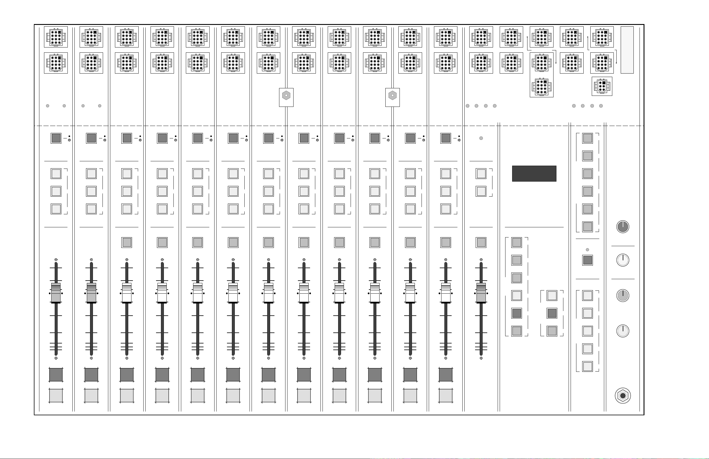
R-5 Console Controls and I/O Connectors
G
A
I
NVU
G
A
I
N
ON
ON
OFF
ON TALLY
TB LOGIC
TEL
HDPN
CR MUTE
STUDIO MUTE
TB BUS
CUE LOGIC
CR
"ON AIR"
RELAY
FET
H
L
A
H
L
B
F
A
D
E
R
FET
CUE
MIC INPUT MUTE CUE SPKR
CUE
PGM
PGM
AUD
MODEL R-5 AUDIO CONSOLE — SIGNAL FLOW DIAGRAM
TB
OFF
TEL
PGM
AUD
SOURCE
L
AFET
CUE LOGIC
EXT
CUE LOGIC
FROM
CALLER
CR MUTE
STUDIO MUTE
TB BUS
CUE LOGIC
J
U
M
P
E
R
S
A/B
ON
OFF
STOP
START
READY
LOGIC
OFF CUE LINE
INPUT
A/B
FET TEL
PGM
AUD
R
F
A
D
E
GAIN SET
JUMPERS
4/–10dBu
+
R
L
BR
CUE
PGM
AUD
R
F
A
D
E
LOGIC
LT
RT
VU
EXT1
PGM
EXT2
AUD
TEL
EXT 2R
L
EXT 1R
L
LT
RT
G
A
I
NFET
H
LLT
H
LRT
STUDIO
G
A
I
NFET
H
LLT
H
LRT
CUE TO
CR
OPTION
TB
TRIM
H
LLT
H
LRT
H
LLT
H
LRT
H
L
H
L
OUTPUTS and
MONITORS
INCLUDED ACCESSORIES
REC PLAY FF RW RTZSTOP
TAPE REMOTE
DISPLAY
TIMER 6
5
4
1
3
2STEREO LINE
PRESELECTOR
LT
RT
TRIM
VU
AUD
LT
RT
VU
TRIM
TRIM
HOLD STARTRESET
CUE
FET
IN
OUT INSERT
CUE
FET
TO CALLER
INTERNAL PWR AMP
INTERNAL
PWR AMP
R
SIMPLE PHONE
CUE
FET
TRIM
TRIM
TRIM
TRIM
TRIM
TRIM
TRIM
TRIM
DIM
RESISTORS
R5 / Jan 99 Page 1 - 11
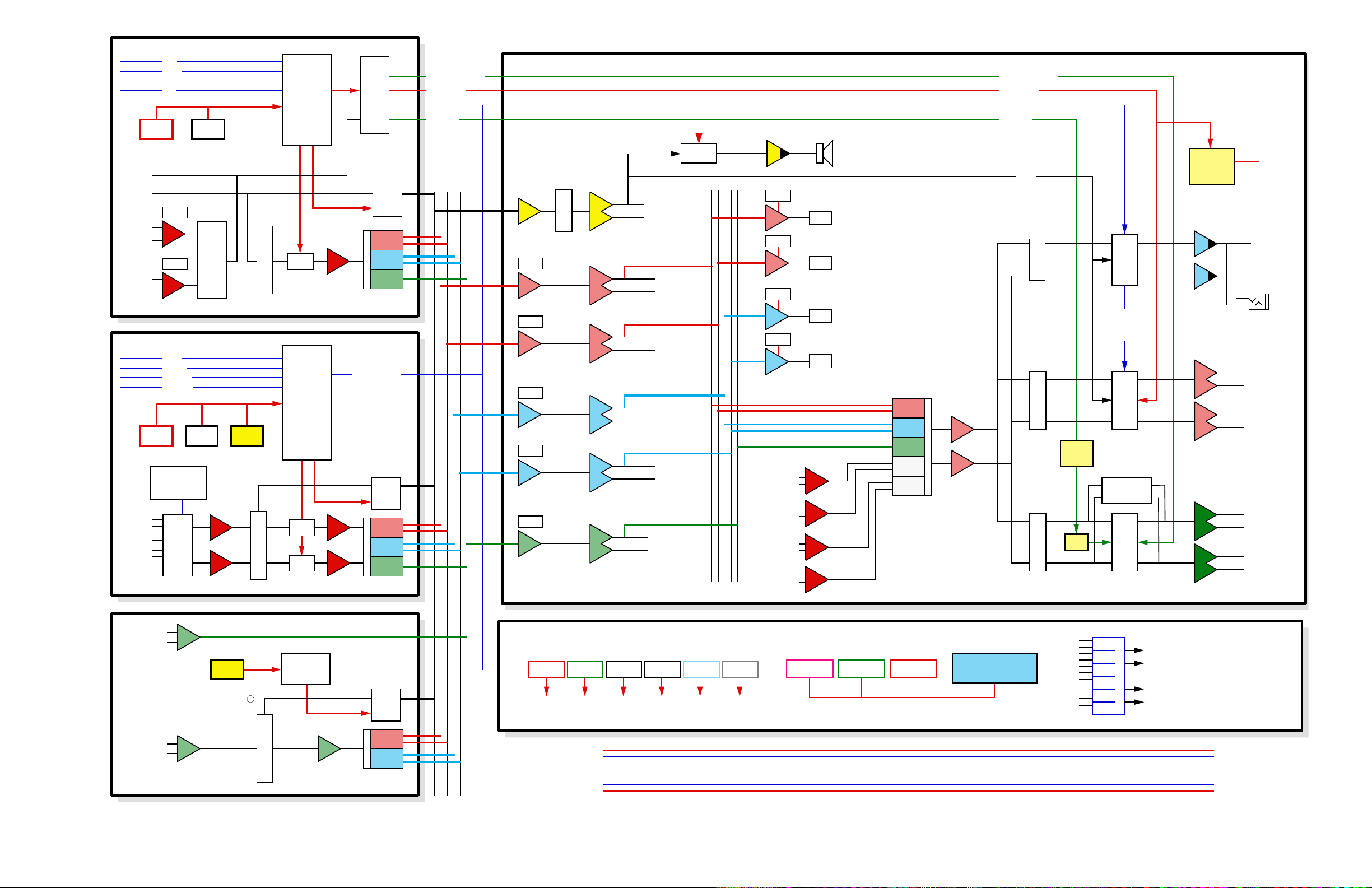
R-5 Console System Signal Flow Diagram

Page 1 - 12
R-5 / Jan 97
FIRST STEPS/BASIC INFO
PERFORMANCE SPECIFICATIONS
(Unless otherwise noted, test conditions are +4dBu output; +4dBu line
input, -50dBu mic input)
FREQUENCY RESPONSE
Line (20Hz-20KHz) ±1/4 dB
Mic (20Hz-20KHz) ±1/4 dB
DYNAMIC RANGE
Line 110dB
Mic 98dB
S/N RATIO (ref +8dBu)
Line 90dB
Mic 78dB
HEADROOM
ref +4dBu 24dB
OFF ISOLATION
1 KHz -95dB
20 KHz -70dB
ASSIGN ISOLATION
1 KHz -100dB
20 KHz -75dB
THD + N (20Hz-20KHz)
Line, +4dBu .007%
Line, +16dBu .007%
Mic, +16dBu .010%
CMMR (mic @60Hz) -65dB
IMD (SMPTE)
Line, +16dBu .006%
Mic, +16dBu .007%
DIM
Line, +24dBu .003%
Mic, +24dBu .004%
MAXIMUM INPUT
Line +28dBu
Mic –12dBu
MAXIMUM OUTPUT
+28dBu
MAXIMUM INPUT GAIN
Line 26dB
Mic 85dB
GAIN TRIM
Line settings 0dB,+14dB
Mic range 32dB
(-50dBu in; -12dB to +20dB)
BUS CROSSTALK
1 KHz -95dB
20 KHz -70dB
SLEW RATE 15V/µs
PHASE RESPONSE
input to output <25°
PHASE DIFFERENCE
left to right <1°
OVERALL DIMENSIONS
front-to-back 21-1/2"
width 31-3/8"
meterbridge height 8"
POWER CONSUMPTION
100 watts (120VAC)
Specifications subject to change without notice.

Page 2 - 1
R-5 / Jan 97
MONO MIC INPUTS
Mono Mic Inputs
Chapter Contents:
Overview............................................................................................... 2-2
Signal Flow Diagram............................................................................ 2-2
Controls and Features......................................................................... 2-3
Mono Mic Input Channel Wiring......................................................... 2-4
Audio Connections.............................................................................. 2-4
Logic and Control Wiring .................................................................... 2-5
Drawing – Typical Remote Logic/Control Hook-ups .......................... 2-6
Technical Documentation................................................................... 2-7
PROGRA
M
AUDITION
10"10"
30.3"
31 3/8"
5"
6 1/2"
21 1/2"
#8
woodscre
w
(t
y
p 4)

Page 2 - 2
R-5 / Jan 97
MONO MIC INPUTS
OVERVIEW
Each R-5 audio console is supplied with two mono microphone input
channels; each channel can accept two microphone input signals which
areaccessedbyanA/Binputselectorswitchatthetopofthechannel.There
are individual microphone gain trims provided for each A and B input,
allowing you to match differing signal levels.
Typically the two microphone channels will be used for the operator's
control room mic and a second microphone in another studio; for this
reason the channels may be programmed to automatically mute control
room or studio monitor speakers (factory preset to dim instead of mute -
see page A-10) when they are turned on, to prevent microphone feedback.
MicinputsmayalsobeturnedONandOFFfromaremotelocation,allowing
talent in remote studios to control their microphones directly. It is also
possible to activate TALKBACK-to-CR from another studio.
As you can see by the signal flow diagram below, a pre-fader, pre-on/off
insertpoint isprovided for mic inputs, allowing you to use outboardsignal
processing (equalization, reverberation, compression/limiting, etc.) for
individual channels. Note this patch point is bridged at the factory with an
internal 10Ωresistor; if you will be using an outboard processing loop, the
jumper resistor must be removed. See page A-7.
Once they have passed through the channel's fader, microphone input
signals are assigned to the console's output busses: PROGRAM (stereo),
AUDITION (stereo) and/or TELEPHONE (mono).
ON
EXTERNAL ON
EXTERNAL OFF
REMOTE ON TALLY
ACTIVATE TB
LOGIC
H
L
A
H
L
B
F
A
D
E
R
FET
MONO MIC INPU
T
OFF
TEL
PGM
AUD
J
U
M
P
E
R
S
A/B
TRIM
TRIM
CUE
FET
IN
OUT INSERT
CR MUTE
STUDIO MUTE
TB TO STUDIO
CUE LOGIC
TO CUE ACN
L
R
L
R
M
TO CONSOLE
OUTPUT BUSSES
(CONTROL)
(CONTROL)
(CONTROL)
(AUDIO)
(TB to CR audio)
Mono Mic Input Signal Flow Diagram
If you plan to use an outboard
patchloop,theconsole'sinternal
jumperresistormustberemoved.
See page A-7.
!
R-5 / Jan 99
Page 2 - 3
R-5 / Jan 97
MONO MIC INPUTS
MIC 1
AB
GAIN
TRIM
ASSIGN
A
B
PGM
AUD
TEL
INPUT
0
5
10
15
20
30
40
50
00
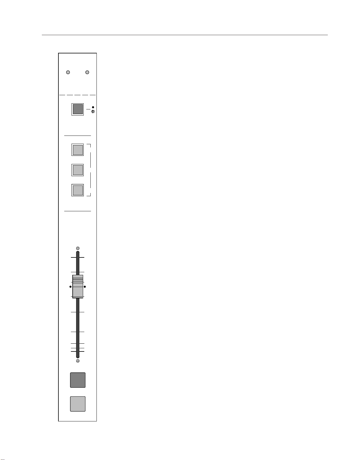
CONTROLS and FEATURES
GAIN TRIM - Concealed front panel gain trim potentiometers (located
justabovetheA/Bselectorswitch,beneaththehingedmeterbridge)provide
a 32dB control range, assuring compatibility with various input levels.
There are separate trimpots for A and B sources.
A/B SOURCE - This switch (LED illuminated) selects between the two
electronicallybalancedmicrophonelevelinputs.The"B"sourceisselected
when the switch is lit.
INSERT POINT (internal) - Mono mic inputs have a patch point available
atthechannel'saudioconnectortoallowinsertionofoutboardprocessing.
The insert point is unbalanced, pre-fader, pre-on/off.
ASSIGN - These three switches (LED illuminated) determine where the
input signal will be sent; they route the channel signal to the console's
stereo Program (PGM), stereo Audition (AUD) and/or mono Telephone
(TEL) busses.
FADER - Long-throw carbon; plug-in for easy service.
ON/OFFSWITCHES-TurnthechannelONandOFF.Brightlyilluminated.
If desired, they may be remotely controlled and programmed for different
automatic functions:
EXTERNAL CONTROL - Microphone channels may be turned ON and
OFF from a remote location; A TALKBACK-to-CR function can also be
remotely activated. The channel's ON switch can control a remote LED
tally indicator (see ON TALLY, bottom of page 2-5). These functions are
intended for a user-provided talent/guest control panel in a separate
studio. Three momentary contact switches are required (see drawing on
page 2-6).
PROGRAMMABLE FUNCTIONS - These include control room MUTE,
studio MUTE/DIM, and TALKBACK-to-STUDIO. These are programmed
via jumpers at the channel's logic connector (see page 2-5). Note the CR
MUTE signal can also activate the console's ON-AIR TALLY RELAY (see
MONITORS chapter, CUE/TALLY connector pinout, page 6-6).
R-5 / Feb 99
Table of contents
Other AudioArts Engineering Recording Equipment manuals

AudioArts Engineering
AudioArts Engineering D-70 User manual

AudioArts Engineering
AudioArts Engineering D-16 User manual

AudioArts Engineering
AudioArts Engineering R-60 User manual

AudioArts Engineering
AudioArts Engineering D-75 User manual

AudioArts Engineering
AudioArts Engineering D-76 User manual

AudioArts Engineering
AudioArts Engineering R-55 User manual


