UC3016-BK/ UC3016-BL/ UC3016-LG/ UC3016-OR/ UC3016-RD
8 07/22/2020
UC3016-BK/UC3016-BL
UC3016-LG/UC3016-OR
UC3016-RD
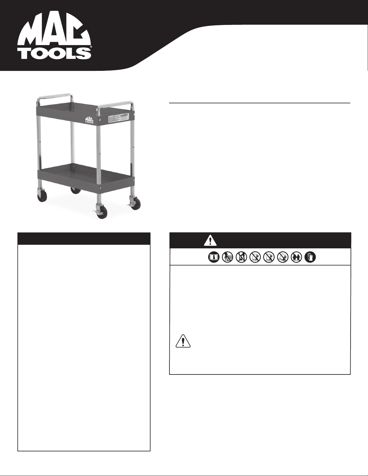
CHARIOT DE SERVICE
CAPACITÉ DE POIDS DU CHARIOT DE SERVICE
Charge totale du chariot avec tous les accessoires . . . . 350 LBS
Charge du plateau supérieur . . . . . . . . . . . . . . . . . . . . . . . . 150 LBS
Charge du plateau inférieur . . . . . . . . . . . . . . . . . . . . . . . . . 150 LBS
VEUILLEZ NOTER : Le chargement du chariot au-delà de sa capacité nominale
peut causer des dommages structurels au chariot ainsi que des dommages
personnels et/ou matériels. Veuillez sensibiliser vos clients aux dangers de
la surcharge. N'essayez pas de pousser le chariot avec des articles placés
sur le couvercle supérieur.
Hauteur totale. . . . . . . . . . . . . . . . . . . . . . . . . . . . . . . . . . . . . 35,75 po
Hauteur du couvercle ..............................32,75 po
Longueur totale ......................................31 po
Longueur totale avec le support de tournevis .........34,25 po
Longueur totale avec la tablette latérale abaissée . . . . . 32,25 po
Longueur totale avec la tablette latérale déployée . . . . . . 45,5 po
Longueur totale avec le support de tournevis et
la tablette latérale déployée .........................48,5 po
Profondeur totale..................................17,13 po
Hauteur du plateau supérieur ...........................3 po
Largeur du plateau supérieur ..........................30 po
Profondeur du plateau supérieur .......................16 po
Hauteur du plateau inférieur ............................3 po
Largeur du plateau inférieur ...........................30 po
Profondeur du plateau inférieur ........................16 po
Garde au sol .......................................7,88 po
Du dessus du plateau inférieur au bas
du plateau supérieure................................ 21.38"
Volume du charriot .................................11,700"³
SPÉCIFICATIONS
• Verrouillez le couvercle et les tiroirs avant de le déplacer. • Appliquez les freins
sur les roulettes verrouillables lorsque ont n’as pas besoin de déplacé l’unité.
• Ne pas tirer; pousser pour déplacer. • Les unités peuvent basculer et vous heurter,
provoquant des blessures. • Le chariot est conçu pour rouler facilement sur des
surfaces planes et ne doit pas être utilisé sur des surfaces inégales ou inclinées.
• N’ouvrez pas plus d’un tiroir plein à la fois. • Ne grimpez pas dans ou sur les
tiroirs. • Gardez hors de la portée des enfants.• Portez des gants lorsque vous
soulevez le chariot par les bords. • Le manque d'observer ces avertissements peut
avoir comme conséquence des blessures corporelles et/ou des dégâts matériels.
AVERTISSEMENT: Ce produit peut vous exposer à des produits chimiques
y compris le nickel, reconnu par l’État de la Californie comme causant
le cancer et des anomalies congénitales ou d’autres effets nuisibles
sur la reproduction. Pour de plus amples informations, aller
à www.P65Warnings.ca.gov.
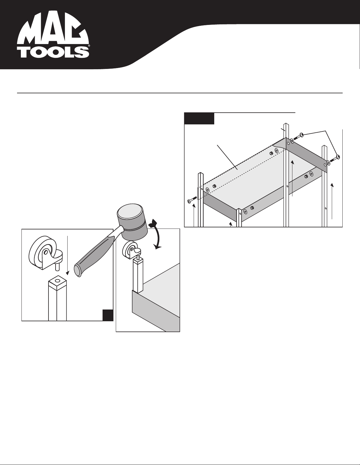
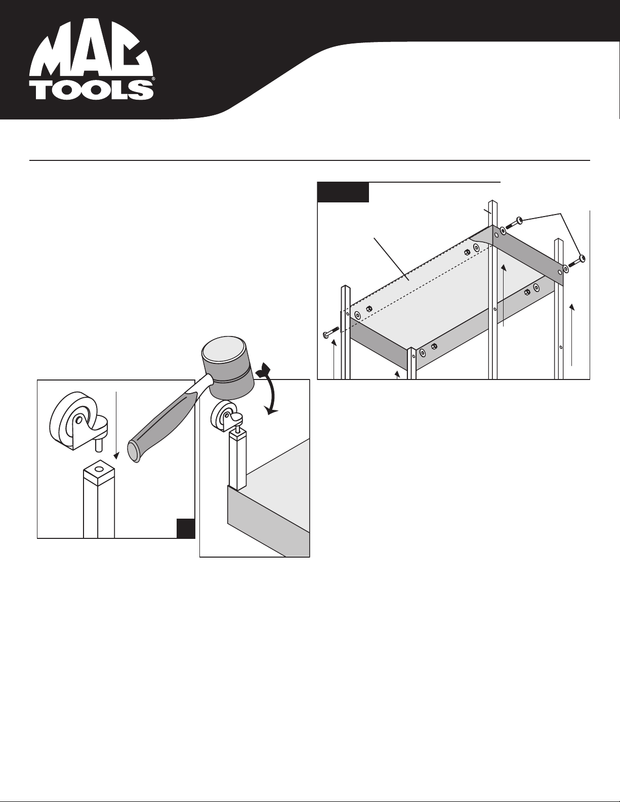
MANUEL DE FONCTIONNEMENT
Lisez et comprenez bien toutes les instructions. Le manque d’observer toutes les
instructions énumérées ci-dessous, peut entraîner une décharge électrique, un feu
et/ou causer de sérieuses blessures corporelles. Veuillez lire et bien comprendre
toutes les instructions. Tout manquement aux instructions indiquées ci-après
pourrait entraîner un choc électrique, un incendie, une explosion et/ou des blessures
personnelles graves. Il est de la responsabilité du propriétaire de s'assurer que tout
le personnel lise ce manuel avant d'utiliser l'appareil. Il revient aussi au propriétaire
de l'appareil de conserver ce manuel en bon état et dans un endroit accessible
permettant au manuel d'être vu et lu par tous. Si le manuel ou les étiquettes du
produit sont perdus ou illisibles, contactez MAC Tools®pour les faire remplacer. Si
l'utilisateur-opérateur de l'appareil ne maîtrise pas bien l'anglais, les instructions
relatives au produit et aux mesures de sécurité devront être lues et discutées avec
l'opérateur dans sa langue maternelle par l'acheteur- propriétaire ou toute personne
habilitée par lui à le faire, en s'assurant que l'opérateur en comprend bien le contenu.