Figure 11) Attaching the blade
to the shaft.
MINI INSTRUCTIONS MANUAL Vegetables cutter MKJ2-250
1. Introduction
1.1 Vegetable cutters series MKJ2-250 are modern gastronomic machines, meeting the requirements
of the terms, both in standard of hygiene and safety of using.
1.2 Compliance with the recommendations contained in the manual and use the machine as inten-
ded, will provide a safe and long-term performance.
1.3 The manufacturer can not be held responsible for any consequences resulting from improper
maintenance of machine instructions.
1.4 Machines MKJ2-250 come in two variants with different power supply methods 400/230V (MKJ2-
250.1) 3-phase current, or 230V 1-phase current with revolutions adjustment(MKJ2-250.2).
2. Apply
Vegetable cutter is used for cutting all kinds of raw fruits and vegetables into slices, chips and
pulp, and for use cube attachement - even for cube, as well as for grinding yellow cheese. Largely eli-
minates the manual work effort shredding vegetables and fruits, and provides lower costs by reducing
the time to prepare meals.
3. Prepare for instalation
After unpacking the machine, check the completeness of the equipment according to specifications.
Then hopper cover and knife grinders rinse with hot water. For storage of grinding knives there is a special
base, which can be bought separately. Knives should be protected from contamination. After each use,
wash them in warm water, dry and rub with dining olive.
4. Connection to the power supply and test run
Machine MKJ2 -250.1 must be supply voltage 3 x 400 V with protective conductor and neutral. The
power cables should be 1.5 mm2, with fuses rated at 6A inserts in each of the three phases. Installation
should be completed with three phase socket, the ground wire should be connected to the terminal mar-
ked with the ground. Supply should be checked by authorized persons, in terms of the effectiveness of
protection against electric shock. Cable length of the machine is about 2.5 m and ends with a five-plug.
Socket should be near the position of the machine.
WARNING - Applies to MKJ2-250.1
When you first run the machine and the shaft does not rotate and red light slow flash, it means that
the phase wires are connected improperly. In this case, in the plug of Power cord should be replaced the
connection of the phase wires.
MKJ2-250.2 machines adapted to 1-phase current supply must be connected to a 230V socket with
an earthing pin.
5.
The drive unit is driver by integrated worm gear and is equipped with a magnetic safety switches
that prevent the inclusion of the drive with the cover is open or the pusher removed. Durring slicing, each
time you open the pusher to fill the food cutter, the machine automatically turns off, but you do not need
every time to press the power switch (green button). During the pusher service indicator light is lit. Howe-
ver, when you open the cover for replacement the disc or cleaning trough, after closing it again, re-press
the power switch button (green) because a safety switch located on the lid makes off power to the engine
and then the lamp goes out.
6. Installing shredding discs and the fidding box
Before replacing discs,the machine must be deactivated by the main switch (red button). The signal-
ling lamp comes off. After opening the cover, hold the shredding disc in two hands and insert on the shaft
so that the bayonet recesseson the disc mounting sleeve will align with the pins on the shaft. After fully
inserting the disc,turn it slightly to the left. In order to remove a shredding disc, follow the above procedure
in the reverse order. Durring operation,the cutting disc automatically lock on the roller as the shredder shaft
rotation direction is oposite to the direction of the side recess of the bayonet lock. In order to remove the fe-
eding cover,unfasten the clip on the left side of the machine and remove the cover from the hinges located
on the right side of the machine slightly turning the lid sideways back and forth.
In order to fix the feeding cover, follow the above procedure in a reverse order, insert the cover into
the hinges in the direction opposite in relation to its removal.
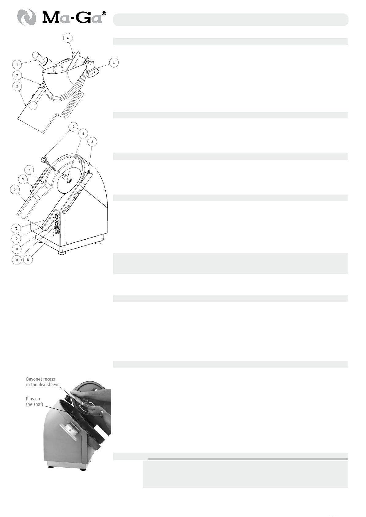
Figure 4 Main components
and parts of MKJ2-250
1. Pusher
2. Feedingcover
3. Driveunitwithatrough
4. Hold-downelement
5. Scraper
6. Outputshaft
7. Covermagneticmicroswitch
8. Hold-downelementmagnetic
microswitch
9. Holdingclip
10. WhitesignallingLED
11. RedsignallingLED
12. Machinepowerswitch
13. Machineturnoffswitch
14. Revolutionsadjustmentknob
(forMKJ2-250.2)
Warning:
A correctly fixed and clipped feeding cover activates the emergency switch allowing for
machine activation by means of the main switch (green button). However, the cutter may
be activated not before the feeding opening is closed by means of the hold – down element
(before that, the signalling lamp must indicated the machine activation status).


