manuals.online logo
Brands
  1. Home
  2. •
  3. Brands
  4. •
  5. Magellan
  6. •
  7. Indoor Furnishing
  8. •
  9. Magellan VK-2124 User manual

Magellan VK-2124 User manual

www.classicexhibits.com
Step 1
Page 1 of 4
866.652.2100
© 2015
WHEN DISASSEMBLING ALUMINUM EXTRUSION, TIGHTEN ALL
SETSCREWS AND LOCKS TO PREVENT LOSS DURING SHIPPING
Order #XXXXX -
Perspective View
Plan View 20’
10’
VK-2124 Modied - 10x20 - General Layout
www.classicexhibits.com
Step 2
Page 2 of 4
866.652.2100
© 2015
WHEN DISASSEMBLING ALUMINUM EXTRUSION, TIGHTEN ALL
SETSCREWS AND LOCKS TO PREVENT LOSS DURING SHIPPING
Order #XXXXX - General Information
Using You Set-up Instructions:
The Visionary Designs Set-up Instructions for Magellan displays are created
specifically for your configuration. They are laid out sequentially, including an
exploded view of the entire display and a logical series of detailed steps for
assembly. We encourage you to study the instructions before attempting to
assemble your exhibit.
THIS IS VERY IMPORTANT!
Each page reminds you to tighten the setscrews after disassembling your
exhibit to prevent loss of the locks and setscrews (see below in red).
Cleaning & Packing Your Display:
1) Use care when cleaning aluminum extrusions or acrylic inserts. Use only
non-abrasive cleaners.
2) When cleaning laminate inserts or counter tops, use mild cleansers and
a soft material such as cotton.
3) Keep all display components away from extreme heat and long exposure
to sunlight to avoid warping and fading.
4) Retain all packing materials. It will make re-packing much easier and will
reduce the likelihood of shipping damage.
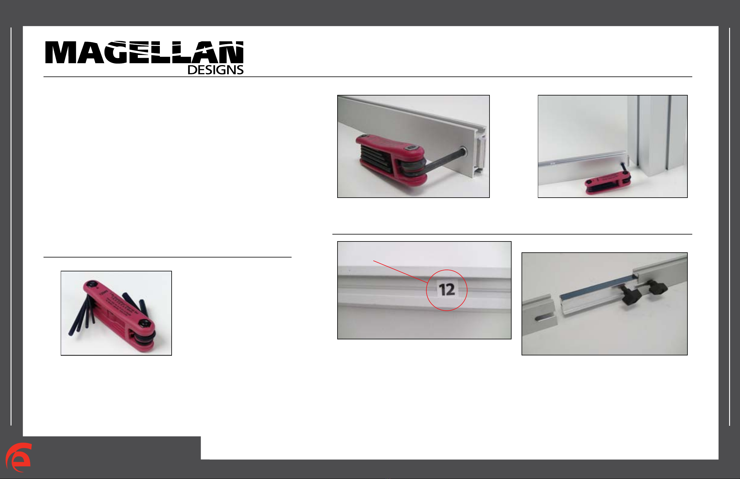
Hex Key Tool
Typical Connection Typical Connection
Most visionary design exhibits can
be assembled with the supplied Hex
Key Tool. Occasionally, a flat head
screwdriver may be required.
Detail A: Most horizontal extrusion connections have a patented expandable lock. This lock inserts into
the groove of an opposing extrusion. Tightening the lock with the Hex Key Tool expands the lock and creates
a strong positive connection.
Numbered
Label
Detail B: Each extrusion contains a numbered label that
corresponds to set-up instructions. The label is located
within a groove of the extrusion (when possible). Visionary
Design labels contain Black numbers unless otherwise
specified.
Horizontal Connection
Detail C: A rectangular connection bar with plastic
T Knobs is inserted between two horizontal extrusions
joined end-to-end. Turn the knobs clockwise to tighten.
Do Not Overtighten.
www.classicexhibits.com
Step 1
Page 1 of 4
866.652.2100
© 2015
WHEN DISASSEMBLING ALUMINUM EXTRUSION, TIGHTEN ALL
SETSCREWS AND LOCKS TO PREVENT LOSS DURING SHIPPING
Order #XXXXX - Backwall Assembly
When assembled
5B 2
3
13A 14A
15A 16A
13A
17A
18A
14A
15A 16A
1
11
1
4
3
4
3
4
3
4
22
2
6B
8B 10B
12B
Item
1
2
3
4
5B
6B
7B
8B
9B
10B
11B
12B
13A
14A
15A
16A
17A
18A
Qty.
4
4
4
4
1
1
1
1
1
1
1
1
2
2
2
2
1
1
Description
Oval Base Plate
35”h Vertical Backwall Support
11.396”w Horizontal Extrusion
4.318”w Horizontal Extrusion
49.55” Curved Vertical Extrusion
42”h Vertical Extrusion
49.55” Curved Vertical Extrusion
42”h Vertical Extrusion
49.55” Curved Vertical Extrusion
42”h Vertical Extrusion
49.55” Curved Vertical Extrusion
42”h Vertical Extrusion
44”w Horizontal Extrusion
24”w Horizontal Extrusion
= Connector A
*
*
*
*
*
*
*
**
*
= Connector B
Steps:
1) Attach oval base plates [1] to verticals [2] using bolts as shown.
2) Attach horizontals [3,4] to verticals [2].
3) Attach upper verticals to lower curved verticals.
4) Connect horizontals [13A,14A] together.
5) Attach vertical assemblies to horizontals [3,4].
6) Attach horizontal assemblies between vertical assemblies.
7) Attach horizontals [17A,18A] between to assembled sections.
8) Velcro attach graphics to back of assembled backwall.
11B
7B 9B
Graphic Attachment
Apply graphic to back
of assembled backwall.
Velcro at lower
back of bar
Velcro at
back of bar
Velcro at upper
back of bar
www.classicexhibits.com
Step 2
Page 2 of 4
866.652.2100
© 2015
WHEN DISASSEMBLING ALUMINUM EXTRUSION, TIGHTEN ALL
SETSCREWS AND LOCKS TO PREVENT LOSS DURING SHIPPING
Order #XXXXX -
Backwall Workstations Assembly
Steps:
1) Attach horizontals [20-21] between verticals [19B] and assembled backwall.
2) Attach flange plates [19a] atop verticals [19B] using bolts as shown.
3) Place counter atop supports and secure in place as shown. Refer to detail.
4) Attach graphic to verticals [19B] using caps. Refer to detail.
5) Attach monitor mounts to assembled backwall. Refer to detail.
19B
19a 19a
19B
20
21 21
20
When assembled
*
*
*
*
*
**
*
*
**
**
Graphic
Cap
V20
Slide connector with stud into
groove of extrusion and
twist to secure in place. Attach
graphic with cap as shown.
Graphic to Post Attachment Monitor Mount Attachment
Holes
Attach monitor mount
plate to vertical using
setscrews provided.
Screw Screw Counter Counter
Graphic Graphic
Counter Top Attachment
Insert screws located
on underside of counter
into holes on flange plate
and secure with wing nuts.
Wing Nut
Item
19B
19a
20
21
Qty.
4
4
4
4
Description
37.5”h Vertical Extrusion
Flange Plate
9.3552"w Horizontal Extrusion
15.7689"w Horizontal Extrusion
www.classicexhibits.com
Step 3
Page 3 of 4
866.652.2100
© 2015
WHEN DISASSEMBLING ALUMINUM EXTRUSION, TIGHTEN ALL
SETSCREWS AND LOCKS TO PREVENT LOSS DURING SHIPPING
Order #XXXXX -
Backwall Attachments
When assembled
Steps:
1) Attach graphic header to upper horizontals.
Refer to Graphic Header Attachment detail.
2) Attach lights atop backwall.
Refer to Light Connection detail.
Light Connection
Attach lights to
backwall where
desired and
tighten in place.
Graphic Header Attachment
Header
Graphic
Screw Cap
Insert screw cap thru hole of
header into threaded hole of
horizontal extrusion. Turn screw
cap clockwise to tighten and
secure header in place.
Horizontal
Extrusion
*
Graphic Header
22
22
*
*
*
*
*
*
*
*
*
www.classicexhibits.com
Step 4
Page 4 of 4
866.652.2100
© 2015
WHEN DISASSEMBLING ALUMINUM EXTRUSION, TIGHTEN ALL
SETSCREWS AND LOCKS TO PREVENT LOSS DURING SHIPPING
Order #XXXXX -
Pedestal Assembly - Qty.2
Item
1
2
3
4
5
6/6a
7
8
9/9a
10
Description
38”h Vertical Extrusion w/ Door Hinges
38”h Vertical Extrusion w/ Door Stopper
38.4565” Curved Extrusion w/ S10
22.9803”w Horizontal Extrusion
10.4062”w Horizontal Extrusion
23”w Horizontal Extrusion
22.9803”w Horizontal Extrusion
15.0700”w Horizontal Extrusion
23”w Horizontal Extrusion
Qty.
1
1
1
1
1
1/1
1
1
1/1
1
Steps:
1) Attach lower horizontals between verticals.
2) Attach door to vertical [1]. Refer to detail.
3) Slide infills between verticals and rest atop
lower horizontals as shown.
4) Attach upper horizontals between verticals.
5) Velcro attach shelf supports to inside of
assembled pedestal.
6) Place shelf atop shelf supports.
7) Place counter atop assembled pedestal.
3
1
2
9a
9
8
Counter
When
assembled
*** KEEP Left and Right pedestal wall
assembly together when shipping ***
10
Door
4
76
5
6a
Infill
Infill
Infill
Shelf
Supports
Shelf
Door
Hinge
Hinge
Door Attachment
Slide pin into
hinge attached
to vertical.
Slide door
hinge atop pin.
www.classicexhibits.com
Step 5
Page 5 of 4
866.652.2100
© 2015
WHEN DISASSEMBLING ALUMINUM EXTRUSION, TIGHTEN ALL
SETSCREWS AND LOCKS TO PREVENT LOSS DURING SHIPPING
Order #XXXXX - Case 1 Packing Instructions
Level 2
Base Plate
2
1
1
2 2 2
8 Connectors
Top View of Each Level
Halogen Lights
Graphics
Setup Hardware
Base Plate
Level 1 Level 3
Wings
www.classicexhibits.com
Step 6
Page 6 of 4
866.652.2100
© 2015
WHEN DISASSEMBLING ALUMINUM EXTRUSION, TIGHTEN ALL
SETSCREWS AND LOCKS TO PREVENT LOSS DURING SHIPPING
Order #XXXXX - Case 2 Packing Instructions
Top View of Each Level
Level 1
Header (X2)
Level 2
13&14
15&16
13&14
15&16
10&8
3(4)
4(4)
17&18
6&12
22(2)
7,11,9,5
Level 3
19 19
20(x2)
21(x2)
19B 19B
19B 19B
Level 4
19 19
20(x2)
21(x2)
Level 5
www.classicexhibits.com
Step 7
Page 7 of 4
866.652.2100
© 2015
WHEN DISASSEMBLING ALUMINUM EXTRUSION, TIGHTEN ALL
SETSCREWS AND LOCKS TO PREVENT LOSS DURING SHIPPING
Order #XXXXX - Case 3 Packing Instructions
Top View of Each Level
Level 1 Level 2
CounterCounter
Plex
Level 3
www.classicexhibits.com
Step 8
Page 8 of 4
866.652.2100
© 2015
WHEN DISASSEMBLING ALUMINUM EXTRUSION, TIGHTEN ALL
SETSCREWS AND LOCKS TO PREVENT LOSS DURING SHIPPING
Order #XXXXX - Case 4 Packing Instructions
Level 4
Shelf Supports
Assembled
Side
Top View of Each Level
Counter Top
Shelf Supports
Level 1 Level 5 Level 6
57
Shelf
Level 2 Level 3
Infills
Assembled
Side
810
Assembled
Door
www.classicexhibits.com
Step 9
Page 9 of 4
866.652.2100
© 2015
WHEN DISASSEMBLING ALUMINUM EXTRUSION, TIGHTEN ALL
SETSCREWS AND LOCKS TO PREVENT LOSS DURING SHIPPING
Order #XXXXX - Case 5 Packing Instructions
Level 4
Shelf Supports
Assembled
Side
Top View of Each Level
Counter Top
Shelf Supports
Level 1 Level 5 Level 6
57
Shelf
Level 2 Level 3
Infills
Assembled
Side
810
Assembled
Door

Other Magellan Indoor Furnishing manuals

Magellan VK-1240 User manual

Magellan

Magellan VK-1240 User manual

Magellan VK-1064 User manual

Magellan

Magellan VK-1064 User manual

Popular Indoor Furnishing manuals by other brands

Poliman Branco/Preto - 539.7 Assembling instructions

Poliman

Poliman Branco/Preto - 539.7 Assembling instructions

Hillsdale Furniture CASTILLE 5976-880 quick start guide

Hillsdale Furniture

Hillsdale Furniture CASTILLE 5976-880 quick start guide

Argos HOME New Pagnell 3 Dr 4 Drw Wardrobe... Assembly instructions

Argos

Argos HOME New Pagnell 3 Dr 4 Drw Wardrobe... Assembly instructions

BestMatic TBT-127183.4 Assembly instruction

BestMatic

BestMatic TBT-127183.4 Assembly instruction

Next 680852 Assembly instructions

Next

Next 680852 Assembly instructions

Habitat Minato 320/1662 manual

Habitat

Habitat Minato 320/1662 manual

East West Furniture VANCOUVER DINING CHAIR VAC-C Assembly instructions

East West Furniture

East West Furniture VANCOUVER DINING CHAIR VAC-C Assembly instructions

Init NT-C1112 Assembly instructions

Init

Init NT-C1112 Assembly instructions

Lorell Value Series manual

Lorell

Lorell Value Series manual

Safavieh Furniture Logan ETG4200 manual

Safavieh Furniture

Safavieh Furniture Logan ETG4200 manual

Epic Office Furniture EkoSystem Desk Shelf Assembly instructions

Epic Office Furniture

Epic Office Furniture EkoSystem Desk Shelf Assembly instructions

Spectrum Industries 37234 Assembly instructions/use and care manual

Spectrum Industries

Spectrum Industries 37234 Assembly instructions/use and care manual

Birlea EDG2SBBLK Assembly instructions

Birlea

Birlea EDG2SBBLK Assembly instructions

VIBO SBPDT45/13DXC Assembling instructions

VIBO

VIBO SBPDT45/13DXC Assembling instructions

DURAVIT Brioso BR 7024 Mounting instructions

DURAVIT

DURAVIT Brioso BR 7024 Mounting instructions

Furniture of America CM6130LV Assembly instructions

Furniture of America

Furniture of America CM6130LV Assembly instructions

Dileoffice Atika Instructions for use

Dileoffice

Dileoffice Atika Instructions for use

Bebecar TRAMA ARC instructions

Bebecar

Bebecar TRAMA ARC instructions

manuals.online logo
manuals.online logoBrands
  • About & Mission
  • Contact us
  • Privacy Policy
  • Terms and Conditions

Copyright 2025 Manuals.Online. All Rights Reserved.