Magenta TT10 User manual

TT-10 Turntable
User Manual

INDEX
CONTENT: PAGE:
SAFETY INSTRUCTIONS: 3
INITIAL SETUP: 5
LEVELING THE TURNTABLE 6
TONEARM SETUP (ASSEMBLY REQUIRED) 6
TONEARM SETUP (FACTORY ASSEMBLED) 7
INSTALLING THE CARTRIDGE 8
ADJUSTING THE VTA (VERTICAL TRACKING ANGLE) 9
CARTRIDGE ALIGNMENT 10
CARTRIDGE DOWNFORCE (WEIGHT) 11
CARTRIDGE AZIMUTH 12
DRIVE BELT AND ANTISKATE PLACEMENT 13
TURNTABLE CONNECTION 14
STARTUP AND SHUTDOWN PROCEDURE 15
TROUBLESHOOTING 16
SPECIAL ADJUSTMENTS: TONEARM MOUNT 17

IMPORTANT SAFETY INSTRUCTIONS:
CAUTION: To reduce the risk of electric shock, do not remove the
cover. There are no user-serviceable parts inside; it is
recommended that only qualified personnel service this
component.
OWNER’S MANUAL: Before powering up the equipment, read all
safety and operating instructions and follow them as instructed.
Retain the safety and operating instructions for future reference.
ATTACHMENTS: Use only those attachments recommended by
the unit manufacturer, as others may cause hazards.
ACCESSORIES: Do not place the unit on an unstable cart, stand,
tripod, bracket, or table. The unit may fall, causing injury to a
person or damage to the unit. Mount the unit according to the
manufacturer’s instructions with the suggested mounting
accessory.
WATER AND MOISTURE: Do not use the unit near water (for
example, near a swimming pool, bathtub, washbowl, kitchen sink,
or laundry tub) or in a damp environment (like a basement or
outside in the rain).
OBJECT AND LIQUID ENTRY: Do not push objects of any kind
into the unit through openings as they could touch dangerous
voltage points and short-out parts, possibly resulting in a fire or
electric shock. Avoid spilling liquid of any kind on the unit. If water
or any metal object (such as a paper clip, coin, or staple)
accidentally falls inside the unit, disconnect it from the AC power
source immediately and contact Margules Audio for further
instructions.
HEAT: Position the unit away from heat sources such as
radiators, heat registers, stoves, or other units (including
amplifiers) that produce heat.
GROUNDING OR POLARIZATION: As a safety feature, the unit
may be equipped with a polarized alternating current line plug, in
which one blade is wider than the other. This plug will fit into the
power outlet only one way. If you cannot insert the plug fully into
the outlet, try reversing the plug. If the plug still does not fit,
contact a licensed electrician to update your obsolete outlet. Do
not break the safety purpose of the polarized plug.
POWER SOURCES: Operate the unit only from the power source
indicated on the marking label. If you are unsure of the type of
power supplied to your home, consult your unit dealer or local
power company.
3

IMPORTANT SAFETY INSTRUCTIONS: IMPORTANT SAFETY NOTE:
POWER CORD PROTECTION: Arrange power supply cords so
that they do not suffer from foot traffic or pinching by items placed
on or against them. Please pay close attention to power cords
where plug enter the AC outlet and where they exit from the unit.
OVERLOADING: Do not overload wall outlets, extension cords,
or integral convenience receptacles as this increases the risk of
fire or electric shock.
REPLACEMENT PARTS: When replacement parts are required,
be sure the service technician has used replacement parts
specified by the manufacturer or those having the same
characteristics as the original parts. Unauthorized substitutions
may result in fire, electric shock, or other hazards.
SAFETY CHECK: Upon completion of any service or repairs to
the unit, ask the service technician to perform safety checks to
ensure the unit is in proper operating condition.
Power Cord: The removable power cord provided with your
player has been specifically designed for use with this product,
but other AC cords may be used instead. Consult your dealer for
advice on AC power cords and high-quality wire in your system.
Wiring: Cables running inside walls should have the appropriate
markings to indicate compliance and listing by the UL, CSA, or
other standards required by the UL, CSA, NEC, or your local
building code. Questions about cables inside of walls should be
referred to a qualified custom installer, a licensed electrician, or a
low-voltage contractor.
RECORDING COPYRIGHT: Recording of copyrighted material for
other than personal use is illegal without permission of the
copyright holder.
FCC INFORMATION FOR USER:
CAUTION: Any changes or modifications not expressly approved
by Margules Audio could void the user's authority to operate the
equipment.
4

INITIAL SETUP, INSTALLATION, AND ASSEMBLY:
PLATTER
SPINDLE
CERAMIC BALL
In the following manual, we will cover all the basics needed to set
up your new T3 turntable.
1. INSTALLATION REQUIREMENTS:
It is imperative to place the turntable on a firm, non-vibrating,
horizontally leveled, and solid support.
2. ASSEMBLING THE BEARING AND PLATTER:
2.1: Carefully insert the ball bearing into the spindle hole. The ball
bearing is made from ceramic. If the platter is dropped too hard
when placing it, the ball bearing can break.
2.2: Insert the spindle into the hole carefully, allowing the air to
flow outside of the bearing structure. The bearing has been
pre-lubricated from the factory, and it should be cleaned and
lubricated with thin oil after every 100 hours of use.
2.3: Carefully place the platter on the spindle. DO NOT twist, drop
or force the platter into position; this could damage the bearing
and will void the warranty.
In the next image, we can see the correct order in which all the
pieces should be assembled.
The platter should spin freely after everything is in place.
5
SPINDLE HOLE ON
TURNTABLE BASE

4.1.1 Unpack the eccentric counterweight and gently, holding the
arm in such a way that you won’t damage the tonearm or the pivot
push it into the weight mount, located in the back of the tonearm.
It is recommended that you twist the counterweight left and right
while pushing in the counterweight, this will help to let it slide in.
Moving the eccentric counterweight left and right will shift the
tonearm center of gravity, allowing it to tilt.
4.1.2 Level the eccentric counterweight to allow the tonearm to be
as leveled as possible, as we will continue the final adjustments
on page 10 of this manual.
Unscrew the tip of the cones for leveling adjustment
INITIAL SETUP, INSTALLATION, AND ASSEMBLY:
3. LEVELING THE TURNTABLE:
Before placing the turntable on its final position, make sure that
the surface on which the turntable will be mounted is solid, flat
and stable.
3.1 LEVELING THE TURNTABLE:
After positioning the turntable on its final place, make sure that its
leveled with a bubble level, if you need to adjust the height of the
feet, the turntable spikes can be adjusted.
To adjust the turntable, screw and unscrew the tip of the cones
until the turntable is leveled.
The Motor base is fixed; therefore it cannot be adjusted or
modified.
4. TONEARM SETUP AND CALIBRATION (ASSEMBLY REQUIRED):
Please read the following steps carefully!
The tonearm is factory leveled, but the eccentric tonearm
counterweight and cartridge needs to be installed.
A correct tonearm and cartridge calibration will ensure the best
audio quality and will extend the life of the stylus tip and your
records, so please take time and care to set your turntable
carefully and correctly.
For all the following adjustments, you might need:
Small screwdriver to set the cartridge (Not Provided).
Set of Allen keys 1/16 for all adjustments except for the tonearm
mount 9/64 (Not Provided).
Digital Scale (Provided).
Protractor and VTA Scale (Provided).
4.1 ASSEMBLING THE ECCENTRIC WEIGHT:
In the back of the tonearm, you will find the eccentric
counterweight mount.
DO NOT MOUNT the cartridge until counterweight is installed.
6

INITIAL SETUP, INSTALLATION, AND ASSEMBLY:
4.1.1 Unpack the eccentric counterweight and gently, holding the
arm in such a way that you won’t damage the tonearm or the pivot
push it into the weight mount, located in the back of the tonearm.
It is recommended that you twist the counterweight left and right
while pushing in the counterweight, this will help to let it slide in.
Moving the eccentric counterweight left and right will shift the
tonearm center of gravity, allowing it to tilt.
4.1.2 Level the eccentric counterweight to allow the tonearm to be
as leveled as possible, as we will continue the final adjustments
on page 10 of this manual.
7
INITIAL SETUP, INSTALLATION, AND ASSEMBLY:
4A. TONEARM SETUP AND CALIBRATION (FACTORY
ASSEMBLED):
Please read the following steps carefully!
The tonearm is factory calibrated and leveled, but the shipping
and handling of the turntable can modify the factory settings.
A correct tonearm and cartridge calibration will ensure the best
audio quality and will extend the life of the stylus tip and your
records, so please take time and care to set your turntable
carefully and correctly.
For all the following adjustments, you might need:
Small screwdriver to set the cartridge (Not Provided).
Set of Allen keys 1/16 for all adjustments except for the tonearm
mount 9/64 (Not Provided).
Digital Scale (Provided).
Protractor and VTA Scale (Provided).
4A.1 PRE-SET THE CARTRIDGE WEIGHT:
The final downforce (weight) of the cartridge will be adjusted on
page 10 of this manual. This pre-set is for allowing you to
measure and align the cartridge correctly.
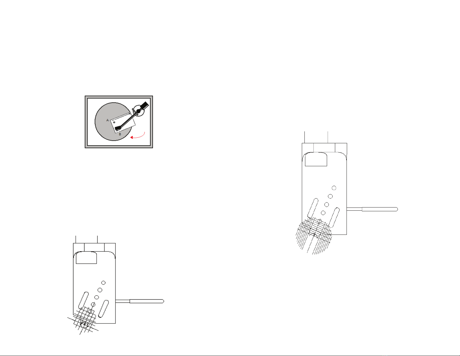
4A.1.1 Unpack the digital scale and insert the batteries (Included).
Place the scale on top of the platter, carefully turn it on and wait
for 2 secods for the scale to tare.
4A.1.2 Carefully remove the stylus guard and unlock the tonearm.
4A.1.3 Using the tonearm lifter, very carefully position the stylus
on the black dot of the scale and allow it to measure the weight.
3. LEVELING THE TURNTABLE:
Before placing the turntable on its final position, make sure that
the surface on which the turntable will be mounted is solid, flat
and stable.
3.1 LEVELING THE TURNTABLE:
After positioning the turntable on its final place, make sure that its
leveled with a bubble level, if you need to adjust the height of the
feet, the turntable spikes can be adjusted.
To adjust the turntable, screw and unscrew the tip of the cones
until the turntable is leveled.
The Motor base is fixed; therefore it cannot be adjusted or
modified.
4. TONEARM SETUP AND CALIBRATION (ASSEMBLY REQUIRED):
Please read the following steps carefully!
The tonearm is factory leveled, but the eccentric tonearm
counterweight and cartridge needs to be installed.
A correct tonearm and cartridge calibration will ensure the best
audio quality and will extend the life of the stylus tip and your
records, so please take time and care to set your turntable
carefully and correctly.
For all the following adjustments, you might need:
Small screwdriver to set the cartridge (Not Provided).
Set of Allen keys 1/16 for all adjustments except for the tonearm
mount 9/64 (Not Provided).
Digital Scale (Provided).
Protractor and VTA Scale (Provided).
4.1 ASSEMBLING THE ECCENTRIC WEIGHT:
In the back of the tonearm, you will find the eccentric
counterweight mount.
DO NOT MOUNT the cartridge until counterweight is installed.
Correct Inorrect

5. INSTALLING THE CARTRIDGE:
Before installing the cartridge, please follow the cartridge
manufacturer's instructions and install the cartridge on the
tonearm.
NOTE: The final cartridge position will be adjusted on pages 9-12
of this manual.
5.1 CONNECTING THE CARTRIDGE:
Before connecting the lead wires to the cartridge, please read the
user manual of the cartridge, and follow the color code on the
back of the cartridge. If the cartridge does not include a color
code, use the following diagram (Figure 5):
4A.1.4 The scale should measure between 1 and 2 grams of
downforce (weight), this will allow to adjust the tonearm and
cartridge alignment. If the downforce is lower than 1g or higher
than 2g please adjust the Eccentric counterweight.
To adjust the downforce (weight) of the tonearm move the
eccentric counterweight:
Gently move the counterweight towards the cartridge to add more
downforce and further from the cartridge to reduce downforce
while the tonearm is located on its guard.
Use the tonearm lifter to raise the tonearm and place it on the
scale until a range of 1-2 grams is measured.
8

INITIAL SETUP, INSTALLATION, AND ASSEMBLY:
6. VTA (VERTICAL TRACKING ANGLE) ADJUSTMENT:
The T3 tonearm mount is factory pre-adjusted and should be
leveled to the platter.
6.1 Pull out the turntable protractor that you received with your
TT-10 turntable, and place it with the circular hole in the center of
the spindle, and align it, so it's pointing to the center of the
tonearm's pivot.
6.2 Place the tonearm on the protractor and align it with the VTA
piece of the protractor.
In the Margules arm, the arm's body should be lining against the
protractor's VTA wall.
As a confirmation, the centerpiece of the protractor should be
pointing the pivot of the arm.
These lines should be parallel to the arm body. This will give you
the VTA alignment and the correct position of the stylus and the
azimuth.
The following images are examples of the results you get if your
VTA is not yet correctly adjusted, which means the turntable still
needs some adjustment.
.
Lift or lower the tonearm with the tonearm height adjustment allen
screw until it is parallel with the VTA lines on the protractor.
Once that is done, retighten the tonearm height adjustment screw.
9

INITIAL SETUP, INSTALLATION, AND ASSEMBLY:
7. CARTRIDGE ALIGNMENT:
Move the tonearm against the internal VTA wall of the protractor.
As explained in the VTA adjustment, on page 9.
To help during the alignment procedure, do not tighten the screws,
have them slightly loose so you can move the cartridge while
adjusting.
Adjust the pickup cartridge, so the needle tip rests on the cross
point of the protractor circled, Adjust the cartridge so that the
cantilever is aligned with the line of the protractor, this will ensure
the tangential adjustment.
Once you have achieved that, carefully tighten the screws of the
cartridge. Doble check a proper tangency adjustment by moving
the arm and placing the needlepoint in the second web, the one
nearer the center.
Then check the needle tip and cartridge are aligned with the other
point on the protractor that is closer to the spindle (you will have
to slightly rotate the protractor).
You should have no problem with this if you have the correct VTA.
If required, please read page 9 of this manual.
10

INITIAL SETUP, INSTALLATION, AND ASSEMBLY:
8. CARTRIDGE DOWNFORCE (WEIGHT):
To ensure the best audio quality and extend the life of your
cartridge and records, the downforce must be adjusted.
Please refer to the cartridge user manual to read the
cartridge recommended downforce.
To adjust the downforce, please use the digital scale included with
your new turntable.
7.1 Place the digital scale turned off on the platter, turn it on
gently, and wait 2 seconds, allowing the scale to tare.
7.2 Using the tonearm lifter, move the tonearm until the stylus tip
rests on the black dot in the center of the measuring area, and
lower the tonearm to allow the scale to measure the downforce.
7.3 Using the tonearm lifter, raise the tonearm, and adjust the
downforce by gently pushing or pulling the eccentric
counterweight forward and backward.
7.4 Pushing the counterweight will reduce downforce, and pulling
the counterweight will add more downforce, make small and
gentle movements, use the tonearm lifter, place the stylus on the
scale and take readings until the downforce recommended by the
cartridge manufacturer is reached.
11

INITIAL SETUP, INSTALLATION, AND ASSEMBLY:
9. CARTRIDGE AZIMUTH ADJUSTMENT:
9.1 Using the provided protractor, check the cartridge seen from
the front, it has to be parallel to the engraved lines of the
protractor azimuth graph:
9.2 If the azimuth needs adjustment, rotate the eccentric
counterweight in the back of the tonearm until the cartridge seen
from the front is parallel to the lines of the azimuth adjustment
piece of the protractor, avoid moving the counterweight forward or
backward to avoid changes in the downforce.
You can also use a small mirror to quickly check if the needle tip
is perpendicular to the record.
The T3 tonearm is unipivot. After the azimuth has been adjusted,
tap down on both sides of the head of the axis to make sure that
the head axis appears to be “floating” over the pivot without
touching the tonearm axle, or in other words, when it can easily
move up and down and sideways. Please make sure that the
ltonearm lifter is on the raised position.
In case that the azimuth is aligned but the tonearm is touching the
tonearm axle, further adjustments will be required. Please refer to
page 17 of this manual.
After adjusting the azimuth, you must re-check the cartidge
downforce.
12
Eccentric Counterweight

INITIAL SETUP, INSTALLATION, AND ASSEMBLY:
10. DRIVE BELT PLACEMENT:
10.1 Start by gently placing the drive belt on the grooves of the
motor axis and then on the grooves of the platter.
Slowly spin the platter until the turntable drive belt is set on both
the platter and the motor axis grooves.
The top grooves on the motor axis are for 33 RPM, and the lower
grooves are for 45 RPM.
13
sssss
sssss
11. ANTI-SKATE WEIGHT PLACEMENT:
Place the loop of the weight filament in the hook of the
anti-skating device on the tonearm base.
Place the filament over the anti-skating weight adjustment arm,
and let the weight hang behind it.
Every mark on the anti-skating weight adjustment arm is
approximate to 0.5g.
Adjust the weight, so it matches the weight of your pickup
cartridge.
Distance from mark to mark = 0.5g
Eccentric Counterweight
Anti-Skate Weight

14
INITIAL SETUP, INSTALLATION, AND ASSEMBLY:
12. TURNTABLE CONNECTIONS:
When connecting the turntable, the cables should rest on the platform you placed your turntable on, and not pull the turntable back or
sideways.
It is essential to make sure the cables don’t mess with the turntable level setup in the beginning when all of the connections are made.
To ensure that the cables are not modifying the turntable level, you can check the motor suspension by pushing down the turntable body
next to the motor, and the turntable body should move up and down freely.
First, connect the RCA (1) output and ground (2) from the turntable to the FZ 47 DB phono preamplifier input (3) and ground (4),
respectively.
Then connect the output of the phono preamplifier (5) to your preamplifier.
Finally, plug both equipments to the 127 AC (6,7).
Follow this diagram to make the connections:

INITIAL SETUP, INSTALLATION, AND ASSEMBLY:
13. STARTUP PROCEDURE
To start up your turntable, verify that all the connections and
adjustments mentioned previously have been done correctly.
Once that is done, follow the next steps.
Switch the power button to the ON position.
Place vinyl on the platter.
The motor is a very low torque motor, and produced very low
vibrations and noise, therefore to start it, spin the platter
clockwise manually a few turns, reaching the desired speed
of 331/3 rpm or 45 rpm and the motor will start and will
continue spinning the platter at the correct speed.
Select the desired RPM by lowering or raising the turntable drive
band from the motor axis. The top grooves on the pulley are for
33 RPM, and the lower grooves are for 45 RPM.
Raise tonearm by the lever, and set to the position where de vinyl
or desired song begins.
Lower tonearm using the tonearm lifter to the desired position on
the record.
Wait for your favorite vinyl or song to start, and enjoy your new T3
turntable.
14. SHUTDOWN PROCEDURE
Raise tonearm with the tonearm lifter.
Place tonearm on the tonearm rest support.
Power OFF the turntable.
Wait for the platter to stop spinning, or stop platter manually.
Remove vinyl from the platter.
15

INITIAL SETUP, INSTALLATION, AND ASSEMBLY:
15. TROUBLESHOOTING:
No sound?
Check that the input selected in your pre-amplifier or system is the
one where you connected your FZ 47 DB phono stage, or your
own phone stage.
Check for an appropriate system volume.
Verify pickup cartridge cables, turntable RCA output cables,
ground cable, and power cable are properly connected.
Sound image shifted to one side?
Verify that the pickup cartridge is properly aligned with the
protractor.
Inspect the needle in the pickup cartridge to see that it is not bent
or damaged.
Noisy or distorted audio?
Verify all connections have been properly made, including the
ground cable from the turntable to the FZ 47 DB phono stage, or
your phono stage. Also make sure that the cartridge type is
compatible with the phonostage.
Verify proper volumes are set at all the gain stages in your sound
system.
Inspect the needle in the pickup cartridge to make sure that it is
not damaged.
Skipping tonearm?
Make sure the tonearm is properly set, and the downforce is
adjusted according to the cartridge manufacturer specifications.
Check the VTA, Azimuth, and arm lifter clearance.
Shifted sound image?
Verify the cartridge has been set up correctly so that it is parallel
to the vinyl, and the needle is perpendicular to the headshell.
Adjust the Anti-Skate weight. If required, please read page 13.
16

SPECIAL ADJUSTMENTS: TONEARM MOUNT
16. TONEARM SUPPORT ADJUSTMENT:
The tonearm support is factory pre-adjusted, and it is already
leveled to the platter.
To adjust it, you can dismount the arm and level it precisely with
relation to the platter with a bubble level, making sure that the
tonearm mount is leveled in all directions. This tonearm mount
can be raised or lowered, depending on the configuration of the
tonearm.
The support can be adjusted in three-axis by adjusting the screws
on the base of the tonearm.
If you tighten the screw in the back of the tonearm base (2), the
tonearm will tilt backward, and raise the tonearm so it might not
touch the record surface, or the arm lifter won't be able to raise
the arm the 2mm required, and the tonearm will not be able to
rotate freely because of possible friction with the tonearm lifter.
If you tighten or loosen the screws on the sides (1 and 3), the axis
will tilt sideways.
Those adjustments can be used to make sure that the tonearm is
floating freely over the pivot.
If it is not correctly aligned, you can have friction into the arm body
cover of the pivot by touching with the internal axle, and the arm
lifter will not work correctly, and cartridge misalignment can occur.
To ensure that the alignment is correct, you must check that on
the outside of the record, and into the record, the arm can rotate
freely, and the lifter has to lift the tonearm by 2mm in relation to
the record, and also the lifter and the tonearm need to have
1-2mm clearance when the record is being played.
17
Other manuals for TT10
1
Table of contents
Other Magenta Turntable manuals