Magic-Pak MGE4-12 Series User manual

Check that equipment complies with all applicable building codes, laws, and regulations for its intended use prior to installation.
508197-01 Issue 2137 Page 1 of 22
Save these instructions for future reference
INSTALLATION AND MAINTENANCE INSTRUCTIONS
MGE4-12/14 Series
Electric Cooling / Gas Heating Packaged Unit
Manufactured By
Allied Air Enterprises LLC
A Lennox International Inc. Company
215 Metropolitan Drive
West Columbia, SC 29170
This is a safety alert symbol and should never be ignored. When you see this symbol on labels or in manuals, be alert to
the potential for personal injury or death.
Improper installation, adjustment, alteration, service
or maintenance can cause property damage, personal
injury or loss of life. Installation and service must be
performed by a licensed professional installer (or
equivalent), service agency or the gas supplier.
WARNING
The installation of this appliance must conform to the requirements of the National Fire Protection Association; the National
Electrical Code, ANSI/NFPA No. 70 (latest edition); and any state/provincial laws or local ordinances. Local authorities
having jurisdiction should be consulted before installation is made. Such applicable regulations or requirements take
precedence over the general instructions in this manual.
CAUTION
*P508197-01*
(P) 508197-01
Table of Contents
Installation ...................................................................1
Start-Up .....................................................................15
Operation...................................................................15
Maintenance..............................................................17
Accessories ...............................................................18
Wiring Diagrams........................................................20
Installation
These units are not approved for mobile home
applications. Such use could result in property damage,
personal injury, or death.
WARNING
General
These instructions explain the recommended method of
installation of the MagicPak All-In-One™ HVAC system
model MGE4 gas heating with electric cooling unit and
associated electrical wiring.
These instructions, and any instructions packaged with
mating components and/or accessories, should be carefully
read prior to beginning installation. Note particularly any
CAUTIONS or WARNINGS in these instructions and all
labels on the units.

Page 2 of 22 508197-01Issue 2137
The MGE4 series are self-contained, gas-red heating
with electric cooling models with optional epoxy-coated
coils. The unit design has been certied by Intertek
Testing Services for compliance with the latest edition of
the American National Standard – ANSI Z21.47 for direct
vent central furnaces. The MGE4 models are certied to
be in compliance with the latest edition of AHRI Standard
210/240. All models are design certied for heating
operation when red with natural or propane gas. Units
must be equipped to use the fuel type provided in the eld.
These instructions are intended as a general guide only,
for use by qualied personnel and do not supersede any
national or local codes in any way. Compliance with all local,
state, provincial, or national codes pertaining to this type of
equipment should be determined prior to installation.
Units certied for less than 2% cabinet leakage using ANSI/
ASHRAE 193 (complies with IECC 2015) are identied on
the rating plate.
In the State of Massachusetts:
This product must be installed by a licensed Plumber
or Gas Fitter. When exible connectors are used, the
maximum length shall not exceed 36”. When lever-type
gas shutos are used, they shall be T-handle type.
WARNING
Because the MGE unit is installed in a conned space,
the return air must be ducted, sealed to the unit and
terminated outside the space containing the unit. Even
a small leak at the return air duct connection can cause
a potentially dangerous negative pressure condition.
WARNING
For your safety, do not store or use gasoline or other
ammable vapors and liquids in the vicinity of this or any
other appliance. Such actions could result in property
damage, personal injury, or death.
WARNING
Installation and servicing of air conditioning equipment
can be hazardous due to internal refrigerant pressure
and live electrical components. Only trained and
qualied service personnel should install or service
this equipment. Installation and service performed by
unqualied persons can result in property damage,
personal injury, or death.
WARNING
The unit must be installed with approved wall sleeve
and louver accessories for safe operation. Improper
installations could result in property damage, personal
injury, or death.
WARNING
Inspection
Upon receipt of equipment, carefully inspect it for possible
shipping damage. If damage is found, it should be noted
on the carrier’s freight bill. Take special care to examine
the unit inside the carton if the carton is damaged. File a
claim with the transportation company. If any damage is
discovered and reported to the carrier, do not install
the unit, as claim may be denied.
Check the unit rating plate to conrm specications
are as ordered.
Limitations
The unit should be installed in accordance with all
national and local safety codes. Limitations of the unit and
appropriate accessories must also be observed.
The outdoor fan is designed to operate against no more
than .10” w.c. static pressure.
Minimum and maximum operation conditions must be
observed to assure proper system performance. Refer to
Table 1 for the ambient operating limitations of the unit.
Table 1. Ambient Temperature Limitations
Outdoor Ambient Air Temperature °F
Minimum DB Maximum DB
Cool Cool Heat
65 115 75
Indoor Ambient Air Temperature °F
Minimum Maximum
DB/WB DB DB/WB DB
Cool Heat Cool Heat
62/57 50 90/72 80
DB = Dry Bulb
WB = Wet Bulb

508197-01 Issue 2137 Page 3 of 22
Unit Dimensions (in.)
Model A B C D E
*MGE4-12-091*P
*MGE4-12-121*P 57-7/8 20-3/4 18-5/8
6
24-5/8
*MGE4-12-181*P
*MGE4-12-241*P 59-7/8 22-3/4 20-5/8 26-5/8
*MGE4-12-301*P 63-7/8 26-3/4 24-5/8 30-5/8
*MGE4-14-361*P 71-7/8 34-3/4 28-5/8 10 38-5/8
24-3/8”
A
4”4”
Return Air
Opening
16”
12”
16”
Supply Air
Opening
24-1/4”
1-1/2”
12”
10-3/4”
Thermostat
Wiring
Connections
Line Voltage
Knockouts
(7/8” and 1-1/8” Dia.)
Top View
13-1/2”
28”
D
33-1/4”
COutdoor
Coil
Combustion
Air Inlet
Vent Pipe
Termination
2-1/2” O.D.
B
3-1/4”
E
Supply Air
Opening
Return Air
Opening
Outdoor Fan Discharge
32-3/8”
Tool-less
Filter
Access
Condensate
Drain 3/4” NPT*
Flame
Inspection
Sight Glass
3/4”
28”
Gas Pipe
Connection
0.5”
9-3/4”
Compressor /
Gauge Ports /
Outdoor Fan Access
Indoor Blower &
Controls Access
Return Air
Opening
Supply Air
Opening
Front View Side View Rear View
* Provisions must be made to properly drain condensate from the drain pan.
Figure 1.

Page 4 of 22 508197-01Issue 2137
Figure 2. Minimum Clearances
Unit must be supported by platform, which must be
level with sill plate of opening in exterior wall.
Platform (field supplied) -
Supply Duct
Opening
Clearance to
Front of Unit
Closet Door / Access
Panel Opening
Minimum 30” wide
1” Min.
Side Clearance
Return Duct
Opening
Exterior Wall
1” Min. Side
Clearance
Closet Wall
Closet Wall
Top View
ExteriorWall
Wall Sleeve
Side Panel
(one each side)
InteriorWall
Minimum
Clearance
3/4" Plywood Riser
(supplied with wall sleeve)
Floor
Front of Unit
Sill Plate
4" Min.
Mounting Strap
(one each side;
supplied with unit)
Supply
Duct Return
Duct
Condensate
Drain Trap
(field supplied)
Gas Piping
(field supplied)
Side View
IMPORTANT
The unit must be installed with approved
wall sleeve and louver accessories for
safe operation. Improper installations could
result in property damage, personal injury,
or death.
Supply Duct Clearances
Minimum Clearances to Combustible
Materials1
Front Sides Top
0” 0” 0”
1 Accessibility clearances take precedence.
Unit Clearances
Minimum Clearances [1]
Front2Sides3
1” 1”
1 Accessibility clearances take precedence.
2 Clearance must accommodate eld-installed
condensate drain line / drain trap and gas line.
3 Additional clearance required if eld-installed
condensate drain line / drain trap is routing alongside
unit.
NOTE: Consult local codes for other clearance
requirements
Accessibility Clearances
The front of the unit must be accessible for service. A
minimum clearance of 30” in front of unit is required for
service.
If the unit is enclosed, a door or access panel aligned with
the front of the unit is the preferred method of providing
access. The door or access panel opening must be a
minimum of 30” wide (centered on the unit) and be as tall
as the unit.

508197-01 Issue 2137 Page 5 of 22
Location
The unit must be installed with approved wall sleeve
and louver accessories for safe operation. Improper
installations could result in property damage, personal
injury, or death.
WARNING
For information on wall sleeves and louver accessories,
see the Accessories section.
This unit is designed to be installed in up to the wall (exterior
wall) installation only. Refer to Figure 2 for additional
details. Accessibility clearances must take precedence
over re protection clearances.
The outside of the unit may be ush with the face of the
exterior wall, and it should not be obstructed with trees,
landscape materials, or building structure. Unit can be
installed recessed with appropriate wall sleeve accessories.
There is no minimum clearance required on locating the
unit to an interior corner of a building.
If the unit is installed in a residential garage, it must be
located or protected to avoid physical damage by vehicles.
The unit must be installed so that no electrical components
are exposed to water.
This unit must be installed level to allow for proper
drainage of the unit base pan and indoor drain pan.
CAUTION
Wall Sleeve and Louver Installation
Refer to installation instructions included with the wall
sleeve and the louver along with Figure 3 for guidance in
assembling and installing the wall sleeve and louver.
The sleeve is not intended as the sole support for
the unit. An additional support must be provided for
adequate support (see Figure 3).
CAUTION
Figure 3. Wall Sleeve and Louver Kit Installation
NOTE: Unit must be supported by platform, which must be level with sill plate of opening in exterior wall.
Exterior Wall
Wall Sleeve Top Panel
Wall Sleeve Side Panel
Platform
(field fabricated
and supplied)
Platform Height: Minimum 4”
3/4” Board Added to
Level Platform with
Wall Sleeve Base
(provided with
wall Sleeve)
Lag Screws with Washers
Wall Sleeve Base
Wall Sleeve Side Panel
Wall Sleeve Divider Panel

Page 6 of 22 508197-01Issue 2137
Installing and Securing Unit to Wall Sleeve
Before installing and securing the unit to the wall sleeve,
make sure that the proper louver is installed. Due to the
high temperatures of the combustion products released
from the vent pipe, these units require the use of either
an aluminum louver or polypropylene louver (see the
Accessories section).
1. Make sure the gaskets attached to the sleeve are not
damaged.
2. Verify divider panel is positioned properly. Refer to
Table 2 for wall sleeves that allow for multiple divider
panel locations.
3. Place the unit into the wall sleeve. Lift leading end of
unit and walk unit onto the sleeve. Once in the wall
sleeve, lower the unit into position. This prevents
damage to the base pads. Assure that the unit is level
and completely seated against the gaskets on the
wall sleeve. The unit must be supported by a eld-
fabricated and supplied platform.
Model
ASLEEVE**-2 ASLEEVE**-5
Orientation
of Flange
Two Positions Three
Positions
MGE4-12-09,12 Lower Lower Down
MGE4-12-18,24
UpMGE4-12-30 Upper Middle
MGE4-14-36 NA Upper
Table 2.
Figure 4. Positioning Divider Panel
Flange Up Orientation
Flange Down Orientation
4. Use the two installation brackets to secure the unit to
the wall sleeve (see Figure 7). The units are shipped
with the brackets placed loose on the unit top panel,
beneath packaging. Hook each bracket into the front
edge of the wall sleeve side panel. Position the bracket
so it can be bent around the front corner of the unit.
Remove one of the two screws in that position on the
unit. Line up one of the holes in the installation bracket
with the screw hole and attach the bracket to the unit
with that screw. Make sure to fasten tight enough
that the seal is maintained. Trim o excess bracket if
applicable.
5. Inspect the t up of the unit to the wall sleeve. Verify
that the gaskets of the wall sleeve make a complete
seal to the unit paying particular attention to top and
bottom corners of unit to sleeve seal. Caulk if needed.
Venting
The venting system is an integral part of the appliance.
The venting system must not be modied in any manner
other than what is specied in these instructions.
This appliance should be installed in a location such that
the vent outlet is located in the following manner:
1. Distances to windows that open, building openings, or
public walkways should be consistent with the National
Fuel Gas Code Z223.1.
2. For U.S. installations, the vent system shall terminate
a minimum horizontal clearance of 4’ from electric
meters, regulators, and relief equipment.
3. Flue products from properly adjusted and maintained
units, should not cause degradation to building
materials.
The unit contains a combustion air inducer. The inducer
draws the combustion products out of the heat exchanger
together with dilution air and forces the mixture from the
unit to the outside. No special provisions are required for
supplying air for combustion, nor is a chimney required as
this is a direct vent appliance.
The vent outlet must be extended (see Vent Pipe
Installation).
The venting system is designed for proper operation under
most weather conditions and for wind speeds up to 40 miles
per hour. The venting system should be unobstructed for a
minimum of 2 feet.
Existing Venting Systems
When an existing furnace is removed and replaced, the
MGE4 unit venting system may no longer be sized to
properly vent the attached appliances. An improperly sized
venting system can result in spillage of ue products into
the living space, the formation of condensate, leakage, etc.
Refer to the CAUTION box in the next column for proper
test procedure.

508197-01 Issue 2137 Page 7 of 22
Carbon Monoxide Poisoning Hazard
Failure to follow the steps outlined below for each
appliance connected to the venting system being
placed into operation could result in carbon monoxide
poisoning or death.
The following steps shall be followed for each appliance
connected to the venting system being placed into
operation, while all other appliances connected to the
common venting system are not in operation:
1. Seal any unused openings in the common venting
system.
2. Visually inspect the venting system for proper size
and horizontal pitch, as required in the National Fuel
Gas Code, ANSI Z223.1/NFPA 54 (latest edition)
and these instructions. Determine that there is no
blockage or restriction, leakage, corrosion, or other
deciencies which could cause an unsafe condition.
3. As far as practical, close all building doors
and windows between the space in which the
appliance(s) connected to the venting system are
located and other spaces in the building.
4. Close replace dampers.
5. Turn on clothes dryers and any appliance not
connected to the venting system. Turn on any
exhaust fans, such as range hoods and bathroom
exhausts, so they are operating at maximum speed.
Do not operate a summer exhaust fan.
6. Follow the lighting instructions. Place the unit being
inspected in operation. Adjust the thermostat so
appliance is operating continuously.
7. Test for spillage from draft hood equipped
appliances at the draft hood relief opening after 5
minutes of main burner operation. Use the ame of
a match or candle.
8. If improper venting is observed during any of the
above tests, the venting system must be corrected
in accordance with the National Fuel Gas Code,
ANSI Z223.1/NFPA 54 (latest edition).
9. After it has been determined that each appliance
remaining connected to the venting system properly
vents when tested as outlined above, return doors,
windows, exhaust fans, replace dampers, and any
other gas-red burning appliance to their previous
conditions of use.
CAUTION
Locating Vent Pipe & Extension
Determining the length of the vent pipe extension is
dependent upon which wall sleeve accessory is installed
at the job site for each particular installation.
For proper operation, the vent length must be correct for
the installation. The unit may not operate correctly with
inadequate vent length.
CAUTION
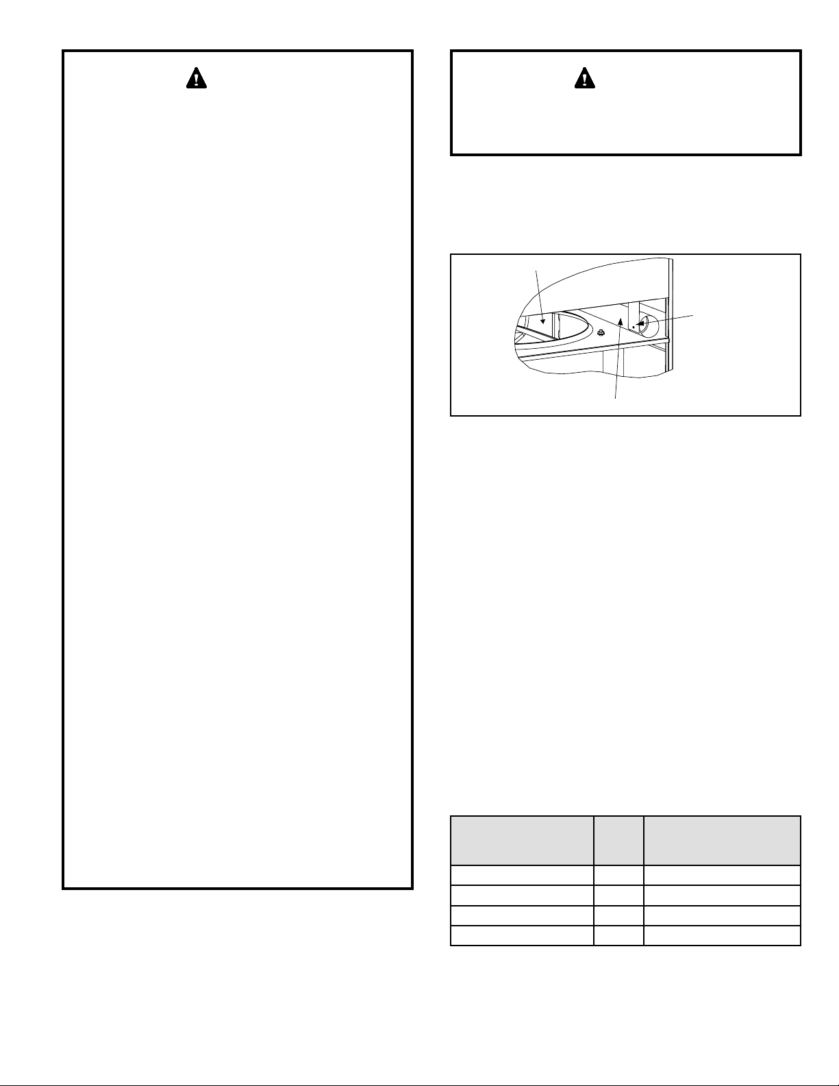
1. Access vent pipe at the side of the unit that will face
the outdoors.
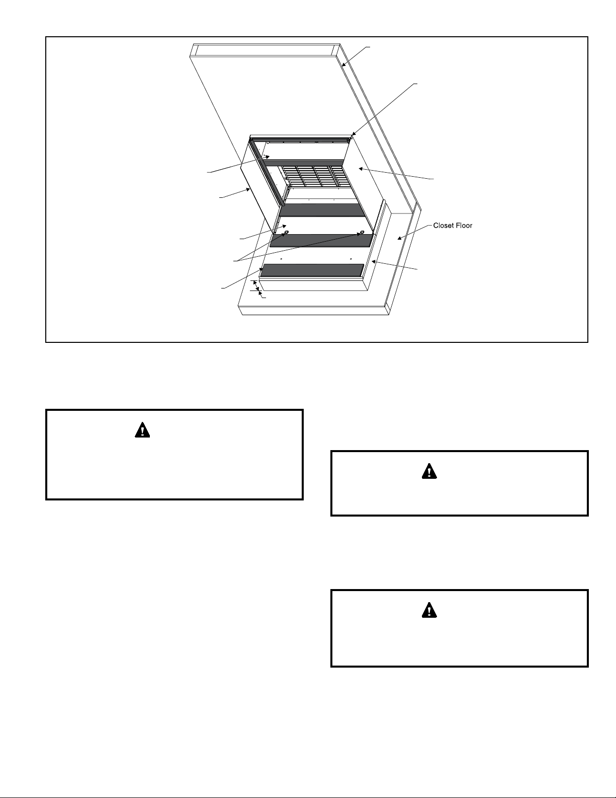
2. The vent pipe and vent pipe extension is located to the
right of the outdoor fan (see Figure 5).
Figure 5. Locating Vent Pipe and Extension
Mounting
Bracket
Vent Pipe
Outdoor Fan
3. Remove the 5/16” screw used to mount the vent pipe
assembly to the mounting bracket. Keep this screw.
4. Five holes have been drilled into the vent extension
(see Figure 6). Four of those holes are provided so
that the vent can be extended the necessary length
required for the installation. The wall sleeve that is
installed determines which of these clearance holes
should be used. Using Table 3 and Figure 6, determine
which clearance hole should be used to position the
vent extension properly. Slide the vent extension
outward and line up the correct clearance hole on the
vent extension with the hole in the vent pipe and the
hole in the mounting bracket.
5. Re-install the 5/16” screw that was removed in Step
3. Thread the screw rst through the clearance hole
in the mounting bracket, the proper clearance hole in
the vent extension, and into the engagement hole in
the vent pipe. The length of the vent pipe extension
that extends out of the cabinet should be as shown in
Table 3.
Table 3. Determining Hole Setting
Wall Sleeve Used Hole #
Approximate Length the
Vent Pipe Extends from
the Cabinet
ASLEEVE6-1, 2, 5 4 5.5 in.
ASLEEVE8-1, 2, 5 3 7.5 in.
ASLEEVE10-1, 2, 5 2 9.5 in.
ASLEEVE12-1, 2, 5 1 11.5 in.

Page 8 of 22 508197-01Issue 2137
Figure 6. Positioning Vent Pipe Extension
Outdoor Fan
0
Vent Extension
Clearance Holes*
* The clearance holes are not marked
on the actual vent extension.
6. Position the vent pipe at the center of the metal wire
grille when using polypropylene louvers. The vent
pipe should have a slight downward slope to allow any
moisture to drain away from the unit as well as being
centered on the metal wire grille.
Ductwork
Ductwork should be designed and sized according to the
methods in Manual Q of the Air Conditioning Contractors
of America (ACCA).
Check unit supply and return air openings for debris
before making ductwork connections.
It is recommended that supply and return duct connections
at the unit be made with exible joints. If exible ducts are
used, a 6” sheet metal starter collar is required.
The supply and return air duct systems should be fabricated
per the designed CFM and static requirements of the job
(see Table 4). Ductwork should not be sized to match
the dimensions of the duct connections on the unit.
The return duct should be sealed to the unit casing and
terminate outside the space containing the unit.
Do not screw into the side of the drain pan or the indoor
coil, which is located above the installation bracket.
CAUTION
Figure 7. Securing Unit
Installation
Brackets
Remove and replace screw to secure bracket
(one each side)
Model
Gas Heating Indoor
Blower
Speed
0.1 “w.c. 0.2 “w.c. 0.3 “w.c. 0.4 “w.c. 0.5 “w.c.
Rise
Range
(F°)
Mid
Rise
(F°)
SCFM
Watts
HP
Temp
Rise
SCFM
Watts
HP
Temp
Rise
SCFM
Watts
HP
Temp
Rise
SCFM
Watts
HP
Temp
Rise
SCFM
Watts
HP
Temp
Rise
0.75 Ton
15MGE4-12-091*P
15 - 45 30
TAP 1
(FAN) 430 46 0.06 --- 370 50 0.07 --- 320 53 0.07 --- 265 57 0.08 --- 200 62 0.08 ---
TAP 2
(COOL)† 375 39 0.05 --- 315 42 0.06 --- N/A N/A N/A --- N/A N/A N/A --- N/A N/A N/A ---
TAP 3
(COOL) N/A N/A N/A --- N/A N/A N/A --- 440 83 0.11 --- 390 87 0.12 --- 340 92 0.12 ---
TAP 4
(HEAT)* 365 35 0.05 31 300 39 0.05 37 240 42 0.06 47 N/A N/A N/A N/A N/A N/A N/A N/A
TAP 5
(HEAT) N/A N/A N/A N/A N/A N/A N/A N/A 460 83 0.11 24 415 88 0.12 27 370 98 0.13 30
24MGE4-12-091*P
25 - 55 40
TAP 1
(FAN) 430 46 0.06 --- 370 50 0.07 --- 320 53 0.07 --- 265 57 0.08 --- 200 62 0.08 ---
TAP 2
(COOL)† 375 39 0.05 --- 315 42 0.06 --- N/A N/A N/A --- N/A N/A N/A --- N/A N/A N/A ---
TAP 3
(COOL) N/A N/A N/A --- N/A N/A N/A --- 440 83 0.11 --- 390 87 0.12 --- 340 92 0.12 ---
TAP 4
(HEAT)* 445 48 0.06 40 390 53 0.07 46 340 56 0.08 53 N/A N/A N/A N/A N/A N/A N/A N/A
TAP 5
(HEAT) N/A N/A N/A N/A N/A N/A N/A N/A 530 102 0.14 34 480 108 0.14 37 440 114 0.15 41
N/A: Do not operate unit using this blower speed at this external static pressure.
† As shipped speed for Cooling operation. Blower speed must be eld adjusted to speed Tap 3 for higher duct static applications.
* As shipped speed for Heating operation. Blower speed must be eld adjusted to speed Tap 5 for higher duct static applications.
# As shipped speed for Low Stage Cooling operation (low duct static).
Table 4. Blower Performance (208V or 230V)

508197-01 Issue 2137 Page 9 of 22
Model
Gas Heating Indoor
Blower
Speed
0.1 “w.c. 0.2 “w.c. 0.3 “w.c. 0.4 “w.c. 0.5 “w.c.
Rise
Range
(F°)
Mid
Rise
(F°)
SCFM
Watts
HP
Temp
Rise
SCFM
Watts
HP
Temp
Rise
SCFM
Watts
HP
Temp
Rise
SCFM
Watts
HP
Temp
Rise
SCFM
Watts
HP
Temp
Rise
1 Ton
15MGE4-12-121*P
15 - 45 30
TAP 1
(FAN) 415 39 0.05 --- 350 43 0.06 --- 285 47 0.06 --- 240 51 0.07 --- 165 54 0.07 ---
TAP 2
(COOL)† 425 46 0.06 --- 370 49 0.07 --- 315 53 0.07 --- N/A N/A N/A --- N/A N/A N/A ---
TAP 3
(COOL) N/A N/A N/A --- N/A N/A N/A --- 475 93 0.12 --- 430 97 0.13 --- 385 101 0.14 ---
TAP 4
(HEAT)* 370 36 0.05 30 315 39 0.05 35 260 42 0.06 43 N/A N/A N/A N/A N/A N/A N/A N/A
TAP 5
(HEAT) N/A N/A N/A N/A N/A N/A N/A N/A 470 80 0.11 24 415 85 0.11 27 370 89 0.12 30
24MGE4-12-121*P
25 - 55 40
TAP 1
(FAN) 415 39 0.05 --- 350 43 0.06 --- 285 47 0.06 --- 240 51 0.07 --- 165 54 0.07 ---
TAP 2
(COOL)† 425 46 0.06 --- 370 49 0.07 --- 315 53 0.07 --- N/A N/A N/A --- N/A N/A N/A ---
TAP 3
(COOL) N/A N/A N/A --- N/A N/A N/A --- 475 93 0.12 --- 430 97 0.13 --- 385 101 0.14 ---
TAP 4
(HEAT)* 450 50 0.07 40 405 53 0.07 44 355 57 0.08 50 N/A N/A N/A N/A N/A N/A N/A N/A
TAP 5
(HEAT) N/A N/A N/A N/A N/A N/A N/A N/A 525 101 0.14 34 485 105 0.14 37 450 110 0.15 40
36MGE4-12-121*P
30 - 60 45
TAP 1
(FAN) 415 39 0.05 --- 350 43 0.06 --- 285 47 0.06 --- 240 51 0.07 --- 165 54 0.07 ---
TAP 2
(COOL)† 425 46 0.06 --- 370 49 0.07 --- 315 53 0.07 --- N/A N/A N/A --- N/A N/A N/A ---
TAP 3
(COOL) N/A N/A N/A --- N/A N/A N/A --- 475 93 0.12 --- 430 97 0.13 --- 385 101 0.14 ---
TAP 4
(HEAT)* 590 87 0.12 45 555 91 0.12 48 515 96 0.13 52 475 100 0.134 56 N/A N/A N/A N/A
TAP 5
(HEAT) N/A N/A N/A N/A 680 138 0.19 39 650 143 0.19 41 615 148 0.198 44 585 153 0.21 46
1.5 Ton
15MGE4-12-181*P
15-45 30
TAP 1
(FAN) 470 54 0.07 --- 400 59 0.08 --- 345 63 0.08 --- 290 67 0.09 --- 235 70 0.09 ---
TAP 2
(COOL)† 670 118 0.16 --- 625 123 0.16 --- 565 131 0.18 --- 525 136 0.18 --- N/A N/A N/A N/A
TAP 3
(COOL) N/A N/A N/A --- 765 184 0.25 --- 730 191 0.26 --- 675 201 0.27 --- 630 206 0.28 ---
TAP 4
(HEAT)* 370 39 0.05 30 305 43 0.06 37 250 46 0.06 45 N/A N/A N/A N/A N/A N/A N/A N/A
TAP 5
(HEAT) N/A N/A N/A N/A N/A N/A N/A N/A 460 92 0.12 24 415 96 0.13 27 370 101 0.14 30
24MGE4-12-181*P
25-55 40
TAP 1
(FAN) 470 54 0.07 --- 400 59 0.08 --- 345 63 0.08 --- 290 67 0.09 --- 235 70 0.09 ---
TAP 2
(COOL)† 670 118 0.16 --- 625 123 0.16 --- 565 131 0.18 --- 525 136 0.18 --- N/A N/A N/A N/A
TAP 3
(COOL) N/A N/A N/A --- 765 184 0.25 --- 730 191 0.26 --- 675 201 0.27 --- 630 206 0.28 ---
TAP 4
(HEAT)* 450 52 0.07 40 385 57 0.08 46 330 61 0.08 54 N/A N/A N/A N/A N/A N/A N/A N/A
TAP 5
(HEAT) N/A N/A N/A N/A N/A N/A N/A N/A 540 116 0.16 33 490 121 0.16 37 450 127 0.17 40
36MGE4-12-181*P
30-60 45
TAP 1
(FAN) 470 54 0.07 --- 400 59 0.08 --- 345 63 0.08 --- 290 67 0.09 --- 235 70 0.09 ---
TAP 2
(COOL)† 670 118 0.16 --- 625 123 0.16 --- 565 131 0.18 --- 525 136 0.18 --- N/A N/A N/A N/A
TAP 3
(COOL) N/A N/A N/A N/A 765 184 0.25 --- 730 191 0.26 --- 675 201 0.27 --- 630 206 0.28 ---
TAP 4
(HEAT)* 590 86 0.12 45 555 90 0.12 48 515 95 0.13 52 475 99 0.13 56 N/A N/A N/A N/A
TAP 5
(HEAT) 715 129 0.17 38 680 135 0.18 39 650 140 0.19 41 615 146 0.20 44 585 151 0.20 46
N/A: Do not operate unit using this blower speed at this external static pressure.
† As shipped speed for Cooling operation. Blower speed must be eld adjusted to speed Tap 3 for higher duct static applications.
* As shipped speed for Heating operation. Blower speed must be eld adjusted to speed Tap 5 for higher duct static applications.
# As shipped speed for Low Stage Cooling operation (low duct static).
Table 4. Blower Performance (208V or 230V)

Page 10 of 22 508197-01Issue 2137
Model
Gas Heating Indoor
Blower
Speed
0.1 “w.c. 0.2 “w.c. 0.3 “w.c. 0.4 “w.c. 0.5 “w.c.
Rise
Range
(F°)
Mid
Rise
(F°)
SCFM
Watts
HP
Temp
Rise
SCFM
Watts
HP
Temp
Rise
SCFM
Watts
HP
Temp
Rise
SCFM
Watts
HP
Temp
Rise
SCFM
Watts
HP
Temp
Rise
1.5 Ton
48MGE4-12-181*P
35-65 50
TAP 1
(FAN) 470 54 0.07 --- 400 59 0.08 --- 345 63 0.08 --- 290 67 0.09 --- 235 70 0.09 ---
TAP 2
(COOL)† 670 118 0.16 --- 625 123 0.16 --- 565 131 0.18 --- 525 136 0.18 --- N/A N/A N/A N/A
TAP 3
(COOL) N/A N/A N/A N/A 765 184 0.25 --- 730 191 0.26 --- 675 201 0.27 --- 630 206 0.28 ---
TAP 4
(HEAT)* 695 141 0.19 51 655 147 0.20 54 620 153 0.21 58 580 161 0.22 62 N/A N/A N/A N/A
TAP 5
(HEAT) 830 214 0.29 43 795 221 0.30 45 760 228 0.31 47 730 236 0.32 49 690 242 0.32 52
60MGE4-12-181*P
40-70 55
TAP 1
(FAN) 470 54 0.07 --- 400 59 0.08 --- 345 63 0.08 --- 290 67 0.09 --- 235 70 0.09 ---
TAP 2
(COOL)† 670 118 0.16 --- 625 123 0.16 --- 565 131 0.18 --- 525 136 0.18 --- N/A N/A N/A N/A
TAP 3
(COOL) N/A N/A N/A N/A 765 184 0.25 --- 730 191 0.26 --- 675 201 0.27 --- 630 206 0.28 ---
TAP 4
(HEAT)* 800 182 0.24 56 770 187 0.25 58 740 191 0.26 60 710 198 0.27 63 675 204 0.27 66
TAP 5
(HEAT) N/A N/A N/A N/A N/A N/A N/A N/A 850 263 0.35 53 825 270 0.36 54 805 276 0.37 56
2 Ton
15MGE4-12-241*P
15-45 30
TAP 1
(FAN) 450 49 0.07 --- 400 52 0.07 --- 345 56 0.08 --- 285 59 0.08 --- 235 65 0.09 ---
TAP 2
(COOL)† 815 206 0.28 --- 780 210 0.28 --- 750 215 0.29 --- 720 219 0.29 --- 690 224 0.30 ---
TAP 3
(COOL) N/A N/A N/A N/A N/A N/A N/A N/A 850 283 0.38 --- 820 287 0.38 --- 785 286 0.38 ---
TAP 4
(HEAT)* 370 36 0.05 30 320 38 0.05 35 250 42 0.06 45 N/A N/A N/A N/A N/A N/A N/A N/A
TAP 5
(HEAT) N/A N/A N/A N/A N/A N/A N/A N/A 465 82 0.110 24 420 85 0.11 26 370 90 0.12 30
24MGE4-12-241*P
25-55 40
TAP 1
(FAN) 450 49 0.07 --- 400 52 0.07 --- 345 56 0.08 --- 285 59 0.08 --- 235 65 0.09 ---
TAP 2
(COOL)† 815 206 0.28 --- 780 210 0.28 --- 750 215 0.29 --- 720 219 0.29 --- 690 224 0.30 ---
TAP 3
(COOL) N/A N/A N/A N/A N/A N/A N/A N/A 850 283 0.38 --- 820 287 0.38 --- 785 286 0.38 ---
TAP 4
(HEAT)* 450 49 0.07 40 400 52 0.07 45 345 56 0.08 52 N/A N/A N/A N/A N/A N/A N/A N/A
TAP 5
(HEAT) N/A N/A N/A N/A N/A N/A N/A N/A 530 99 0.13 34 490 103 0.14 37 450 107 0.14 40
36MGE4-12-241*P
30-60 45
TAP 1
(FAN) 450 49 0.07 --- 400 52 0.07 --- 345 56 0.08 --- 285 59 0.08 --- 235 65 0.09 ---
TAP 2
(COOL)† 815 206 0.28 --- 780 210 0.28 --- 750 215 0.29 --- 720 219 0.29 --- 690 224 0.30 ---
TAP 3
(COOL) N/A N/A N/A N/A N/A N/A N/A N/A 850 283 0.38 --- 820 287 0.38 --- 785 286 0.38 ---
TAP 4
(HEAT)* 600 89 0.12 45 560 93 0.12 48 520 96 0.13 52 485 100 0.13 56 N/A N/A N/A N/A
TAP 5
(HEAT) N/A N/A N/A N/A 700 148 0.20 38 665 153 0.21 40 635 157 0.21 42 600 162 0.22 45
48MGE4-12-241*P
35-65 50
TAP 1
(FAN) 450 49 0.07 --- 400 52 0.07 --- 345 56 0.08 --- 285 59 0.08 --- 235 65 0.09 ---
TAP 2
(COOL)† 815 206 0.28 --- 780 210 0.28 --- 750 215 0.29 --- 720 219 0.29 --- 690 224 0.30 ---
TAP 3
(COOL) N/A N/A N/A N/A N/A N/A N/A N/A 850 283 0.38 --- 820 287 0.38 --- 785 286 0.38 ---
TAP 4
(HEAT)* 720 145 0.19 50 675 151 0.20 53 635 157 0.21 56 595 164 0.22 60 N/A N/A N/A N/A
TAP 5
(HEAT) N/A N/A N/A N/A 820 223 0.30 44 780 232 0.31 46 745 238 0.32 48 710 246 0.33 50
N/A: Do not operate unit using this blower speed at this external static pressure.
† As shipped speed for Cooling operation. Blower speed must be eld adjusted to speed Tap 3 for higher duct static applications.
* As shipped speed for Heating operation. Blower speed must be eld adjusted to speed Tap 5 for higher duct static applications.
# As shipped speed for Low Stage Cooling operation (low duct static).
Table 4. Blower Performance (208V or 230V)

508197-01 Issue 2137 Page 11 of 22
Model
Gas Heating Indoor
Blower
Speed
0.1 “w.c. 0.2 “w.c. 0.3 “w.c. 0.4 “w.c. 0.5 “w.c.
Rise
Range
(F°)
Mid
Rise
(F°)
SCFM
Watts
HP
Temp
Rise
SCFM
Watts
HP
Temp
Rise
SCFM
Watts
HP
Temp
Rise
SCFM
Watts
HP
Temp
Rise
SCFM
Watts
HP
Temp
Rise
2 Ton
60MGE4-12-241*P
40-70 55
TAP 1
(FAN) 450 49 0.07 --- 400 52 0.07 --- 345 56 0.08 --- 285 59 0.08 --- 235 65 0.09 ---
TAP 2
(COOL)† 815 206 0.28 --- 780 210 0.28 --- 750 215 0.29 --- 720 219 0.29 --- 690 224 0.30 ---
TAP 3
(COOL) N/A N/A N/A N/A N/A N/A N/A N/A 850 283 0.38 --- 820 287 0.38 --- 785 286 0.38 ---
TAP 4
(HEAT)* 810 182 0.24 55 775 186 0.25 58 745 191 0.26 60 710 195 0.26 63 680 200 0.27 66
TAP 5
(HEAT) N/A N/A N/A N/A N/A N/A N/A N/A 860 258 0.35 52 830 265 0.36 54 800 270 0.36 56
2.5 Ton
24MGE4-12-301*P
25-55 40
TAP 1
(FAN) 490 55 0.07 --- 465 65 0.09 --- 435 72 0.10 --- 415 81 0.11 --- 390 89 0.12 ---
TAP 2
(COOL)† 930 239 0.32 --- 900 243 0.33 --- 885 250 0.34 --- 835 256 0.34 --- 805 262 0.35 ---
TAP 3
(COOL) N/A N/A N/A N/A N/A N/A N/A N/A N/A N/A N/A N/A 930 325 0.44 --- 900 328 0.44 ---
TAP 4
(HEAT)* 450 47 0.06 40 400 49 0.07 45 350 53 0.07 51 N/A N/A N/A N/A N/A N/A N/A N/A
TAP 5
(HEAT) N/A N/A N/A N/A N/A N/A N/A N/A 530 93 0.12 34 490 98 0.13 37 450 103 0.14 40
36MGE4-12-301*P
30-60 45
TAP 1
(FAN) 490 55 0.07 --- 465 65 0.09 --- 435 72 0.10 --- 415 81 0.11 --- 390 89 0.12 ---
TAP 2
(COOL)† 930 239 0.32 --- 900 243 0.33 --- 885 250 0.34 --- 835 256 0.34 --- 805 262 0.35 ---
TAP 3
(COOL) N/A N/A N/A N/A N/A N/A N/A N/A N/A N/A N/A N/A 930 325 0.44 --- 900 328 0.44 ---
TAP 4
(HEAT)* 600 80 0.11 45 560 84 0.11 48 515 89 0.12 52 475 93 0.12 56 N/A N/A N/A N/A
TAP 5
(HEAT) N/A N/A N/A N/A 705 136 0.18 38 670 141 0.19 40 635 146 0.20 42 600 151 0.20 45
48MGE4-12-301*P
35-65 50
TAP 1
(FAN) 490 55 0.07 --- 465 65 0.09 --- 435 72 0.10 --- 415 81 0.11 --- 390 89 0.12 ---
TAP 2
(COOL)† 930 239 0.32 --- 900 243 0.33 --- 885 250 0.34 --- 835 256 0.34 --- 805 262 0.35 ---
TAP 3
(COOL) N/A N/A N/A N/A N/A N/A N/A N/A N/A N/A N/A N/A 930 325 0.44 --- 900 328 0.44 ---
TAP 4
(HEAT)* 715 140 0.19 50 670 146 0.20 53 630 152 0.20 57 590 159 0.21 61 N/A N/A N/A N/A
TAP 5
(HEAT) N/A N/A N/A N/A 815 218 0.30 44 775 227 0.30 46 740 233 0.31 48 705 241 0.32 51
60MGE4-12-301*P
40-70 55
TAP 1
(FAN) 490 55 0.07 --- 465 65 0.09 --- 435 72 0.10 --- 415 81 0.11 --- 390 89 0.12 ---
TAP 2
(COOL)† 930 239 0.32 --- 900 243 0.33 --- 885 250 0.34 --- 835 256 0.34 --- 805 262 0.35 ---
TAP 3
(COOL) N/A N/A N/A N/A N/A N/A N/A N/A N/A N/A N/A N/A 930 325 0.44 --- 900 328 0.44 ---
TAP 4
(HEAT)* 810 163 0.22 55 775 169 0.23 58 740 173 0.23 60 710 179 0.24 63 680 185 0.25 66
TAP 5
(HEAT) 935 233 0.31 48 900 240 0.32 50 870 245 0.33 52 835 254 0.34 53 810 257 0.34 55
N/A: Do not operate unit using this blower speed at this external static pressure.
† As shipped speed for Cooling operation. Blower speed must be eld adjusted to speed Tap 3 for higher duct static applications.
* As shipped speed for Heating operation. Blower speed must be eld adjusted to speed Tap 5 for higher duct static applications.
# As shipped speed for Low Stage Cooling operation (low duct static).
Table 4. Blower Performance (208V or 230V)

Page 12 of 22 508197-01Issue 2137
Model
Gas Heating Indoor
Blower
Speed
0.1 “w.c. 0.2 “w.c. 0.3 “w.c. 0.4 “w.c. 0.5 “w.c.
Rise
Range
(F°)
Mid
Rise
(F°)
SCFM
Watts
HP
Temp
Rise
SCFM
Watts
HP
Temp
Rise
SCFM
Watts
HP
Temp
Rise
SCFM
Watts
HP
Temp
Rise
SCFM
Watts
HP
Temp
Rise
3 Ton
24MGE4-14-361*P
25-55 40
TAP 1
(COOL)#704 126 0.17 --- 664 131 0.18 --- 626 136 0.18 --- 592 141 0.19 --- 553 147 0.20 ---
TAP 2
(COOL)† 1020 307 0.41 --- 980 313 0.42 --- 940 314 0.42 --- 900 318 0.43 --- 865 323 0.43 ---
TAP 3
(COOL) N/A N/A N/A N/A N/A N/A N/A N/A 965 333 0.45 --- 930 338 0.45 --- 890 344 0.46 ---
TAP 4
(HEAT)* 450 48 0.06 40 385 52 0.07 46 325 55 0.07 55 N/A N/A N/A N/A N/A N/A N/A N/A
TAP 5
(HEAT) N/A N/A N/A N/A N/A N/A N/A N/A 550 107 0.14 33 500 112 0.15 36 450 117 0.16 40
36MGE4-14-361*P
30-60 45
TAP 1
(COOL)#704 126 0.17 --- 664 131 0.18 --- 626 136 0.18 --- 592 141 0.19 --- 553 147 0.20 ---
TAP 2
(COOL)† 1020 307 0.41 --- 980 313 0.42 --- 940 314 0.42 --- 900 318 0.43 --- 865 323 0.43 ---
TAP 3
(COOL) N/A N/A N/A N/A N/A N/A N/A N/A 965 333 0.45 --- 930 338 0.45 --- 890 344 0.46 ---
TAP 4
(HEAT)* 615 82 0.11 44 580 86 0.12 46 540 91 0.12 50 500 96 0.13 54 460 102 0.14 58
TAP 5
(HEAT) N/A N/A N/A N/A 710 129 0.17 38 685 135 0.18 39 650 140 0.19 41 615 145 0.19 44
48MGE4-14-361*P
35-65 50
TAP 1
(COOL)#704 126 0.17 --- 664 131 0.18 --- 626 136 0.18 --- 592 141 0.19 --- 553 147 0.20 ---
TAP 2
(COOL)† 1020 307 0.41 --- 980 313 0.42 --- 940 314 0.42 --- 900 318 0.43 --- 865 323 0.43 ---
TAP 3
(COOL) N/A N/A N/A N/A N/A N/A N/A N/A 965 333 0.45 --- 930 338 0.45 --- 890 344 0.46 ---
TAP 4
(HEAT)* 715 135 0.18 50 675 142 0.19 53 640 148 0.20 56 600 155 0.21 60 560 162 0.22 64
TAP 5
(HEAT) N/A N/A N/A N/A 820 212 0.28 44 785 219 0.29 46 745 227 0.30 48 715 234 0.31 50
3 Ton
60MGE4-14-361*P
40-70 55
TAP 1
(COOL)#704 126 0.17 --- 664 131 0.18 --- 626 136 0.18 --- 592 141 0.19 --- 553 147 0.20 ---
TAP 2
(COOL)† 1020 307 0.41 --- 980 313 0.42 --- 940 314 0.42 --- 900 318 0.43 --- 865 323 0.43 ---
TAP 3
(COOL) N/A N/A N/A N/A N/A N/A N/A N/A 965 333 0.45 --- 930 338 0.45 --- 890 344 0.46 ---
TAP 4
(HEAT)* 825 175 0.23 54 790 179 0.24 57 755 185 0.25 59 720 191 0.26 62 690 197 0.26 65
TAP 5
(HEAT) 935 240 0.32 48 905 246 0.33 49 870 254 0.34 51 845 260 0.35 53 815 266 0.36 55
N/A: Do not operate unit using this blower speed at this external static pressure.
† As shipped speed for Cooling operation. Blower speed must be eld adjusted to speed Tap 3 for higher duct static applications.
* As shipped speed for Heating operation. Blower speed must be eld adjusted to speed Tap 5 for higher duct static applications.
# As shipped speed for Low Stage Cooling operation (low duct static).
Table 4. Blower Performance (208V or 230V)
Filter
All return air must be ltered. A washable lter is furnished
with the unit, located in the return air opening.
If a lter is installed at a separate central return
location, then the factory furnished lter must be
removed from the unit.
If an installation is made in which it is more desirable to
mount the lter exterior to the unit, in the return duct work
or elsewhere, the washable lter can be used or replaced
with a disposable lter. If a disposable lter is used in lieu
of a washable lter, use the information provided in Table 5
when sizing the disposable lter.
Table 5. Minimum Required Surface Area for
Disposable Filters
Model Number Filter Area (in2)
15MGE4-12-09* 175
24MGE4-12-09*
15MGE4-12-12*
24MGE4-12-12*
210
36MGE4-12-12* 285
15MGE4-12-18*
24MGE4-12-18*
36MGE4-12-18*
48MGE4-12-18*
325
60MGE4-12-18*
*MGE4-12-24* 385
*MGE4-12-30* 435
*MGE4-14-36* 480

508197-01 Issue 2137 Page 13 of 22
When proper duct design is applied, eld-provided lters
up to MERV 6 can typically be installed in the unit’s factory
lter location in lieu of a washable lter. If a higher resistance
lter is eld installed in the unit, the added resistance must
be included in the external static pressure and must not
exceed 0.5 in. w.c., including ductwork.
Condensate Drain
Provisions must be made to properly drain condensate
from the drain pan.
Condensate drain connection: 3/4” NPT to 3/4” PVC tting
(schedule 40 minimum). Drain must be trapped as shown
in Figure 8. The drain line should pitch gradually downward
at least 1” per 10’ of horizontal run to open drain. Field
fabricated platform should be 4” minimum to allow for
proper trapping and drainage.
Use thread sealant on the threaded ttings. Install
threaded ttings by hand only. Do not over torque the
ttings.
CAUTION
If local codes require the use of metal condensate lines,
do not thread metal ttings into the unit drain pans. Thread
a PVC tting into the unit drain pans and make the eld
connection to the PVC tting.
NOTE: These units are designed with a redundant drain
system to handle condensate without the need for a
secondary or emergency drain pan. Should the indoor coil
condensate drain system fail, all water is contained within
the unit and the ow is directed into the unit base pan.
From there it will drain into the condensate riser.
Figure 8. Condensate Drain Installation
Electrical Connections
All wiring must be done in accordance with the National
Electrical Code (NEC), ANSI/NFPA No. 70 (latest edition);
or local codes, where they prevail. Any alteration of internal
wiring will void certication and warranty.
Units are factory wired for a 230 volt power supply. If power
supply is 208 volts, it will be necessary to change a wire
connection on unit transformer from 240 volt terminal to
208 volt terminal as shown on the wiring diagram.
Use wiring with a temperature limitation of 75°C minimum.
Run the 208 or 230 volt, single phase, 60 hertz electric
power supply through a fused disconnect switch and
connect to the unit as shown in the unit’s wiring diagram.
The unit must be electrically grounded in accordance with
local codes or, in the absence of local codes, with the
National Electrical Code ANSI/NFPA No. 70 (latest edition).
The power supply to the unit must be NEC Class 1 and
must comply with all applicable codes. A fused disconnect
switch should be eld provided for the unit, and must be
separate from all other circuits. If any of the wire supplied
with the unit must be replaced, replacement wire must be
of the type shown on the wiring diagram.
Electrical wiring must be sized to minimum circuit ampacity
(MCA) marked on the unit. Use copper conductors only.
Each unit must be wired with a separate branch circuit and
be properly fused.
Gas Supply and Piping
Refer to unit rating plate to make sure the furnace is
equipped to utilize the type of fuel that is being provided
(natural or propane).
Any conversion of a natural gas unit to propane gas
must be done by qualied personnel using a conversion
kit available from the manufacturer, following the
instructions in the conversion kit. If done improperly,
over-ring of the burners and improper burner operation
can result. This can create carbon monoxide which
could cause asphyxiation.
WARNING
Gas supply piping should be installed in accordance with
local codes and the regulations of the utility. Piping must
be of adequate size to prevent undue pressure drop.
Consult the local utility or gas supplier for complete details
on special requirements for sizing gas piping.
If local codes allow the use of a exible gas appliance
connector, always use a new approved connector. Do not
use a connector which has previously serviced another
gas appliance.

Page 14 of 22 508197-01Issue 2137
The gas valve supplied with this furnace is rated at 1/2
psig maximum. Any higher pressure may rupture the
pressure regulator diaphragm and may cause over-
ring of the burners and improper burner operation. The
over-ring may result in the creation of carbon monoxide
which could cause asphyxiation.
WARNING
Fire or Explosion Hazard
Failure to follow the safety warnings exactly could result
in serious injury, death, or property damage.
Never test for gas leaks with an open ame. Use a
commercially available soap solution made specically
for the detection of leaks to check all connections. A
re or explosion may result causing property damage,
personal injury, or loss of life.
WARNING
Figure 9. Gas Supply Piping
Return Supply
Drip Leg (field supplied)
Ground Joint Union (field supplied)
Condensate Drain (field supplied)
Compressor /
Gauge Ports /
Outdoor Fan Access
Gas Valve and
Burners Access
Indoor Blower and
Controls Access
Manual Shutoff Valve with 1/8”
NPT Plugged Tapping; Accessible
for Test Gauge Connection
(field supplied)
Filter
A
ccess
Pipe connections must be tight, and a non-hardening pipe
compound resistant to liqueed petroleum gases must be
used.
Connect the gas pipe to the gas pipe connection providing
a ground joint union as close to the gas pipe connection
as is possible to facilitate removal of controls and manifold.
Provide a drip leg on the outside of the furnace. A manual
shuto valve shall be installed in the gas line, outside the
unit, 5’ above the oor, or in accordance with any local
codes.
The furnace must be isolated from the gas supply piping
system by closing the individual manual shuto valve
during any pressure testing of the gas supply piping system
at test pressure equal to or less than 1/2 psig (3.5 kPa) or
14” W.C. If the piping system is to be tested at pressures in
excess of 1/2 psig (3.5 kPa), the furnace and its appliance
main gas valve must be disconnected from the gas supply
piping system.
After gas piping is complete, carefully check all piping
connections (factory and eld) for gas leaks. Use a leak
detecting solution or other preferred means. Some soaps
used for leak detection are corrosive to certain metals.
Carefully rinse piping thoroughly after leak detection has
been completed.

508197-01 Issue 2137 Page 15 of 22
Start-Up
For Your Safety, Read Before Lighting
If you do not follow these instructions exactly, a re
or explosion may result causing property damage,
personal injury, or loss of life.
WARNING
This furnace is equipped with a direct ignition control.
Do not attempt to manually light the burners.
CAUTION
To Light Burners
Figure 10. Gas Valve
Gas Inlet
Gas Inlet
Pressure
Test Ta p
ON / OFF
Switch
Gas Manifold
Pressure
Test Ta p
Regulator
Adjustment
Screw
(Under Cap)
1. Turn o electrical power to unit.
2. Turn the thermostat to lowest setting.
3. Move the gas valve switch to the “ON” position (see
Figure 10).
Operation
Operation of the unit is automatic and will provide heating
and cooling depending on the setting of the thermostat.
Heating
1. Turn on main power supply.
2. Open manual gas shuto valve.
3. Set thermostat system to “HEAT”.
4. Set thermostat to temperature desired.
Sequence of Operation
1. Thermostat calls for heat.
2. Combustion air inducer starts and proper air ow is
proven by the pressure switch closing.
3. Blower continues to operate for 30 seconds prior to
the burners lighting.
4. Ignition control begins spark and opens gas valve. The
burners are lit. Ignition is proved through ame sensor.
5. Supply air blower starts 30 seconds after the burners
light.
6. When the thermostat is satised, the burners and
combustion air inducer shut o.
7. Supply air blower will shut o 120 seconds later.
If the burners should fail to ignite, the ignition control will
try to ignite the burners a total of three times. Should the
burners fail to ignite within the three trials for ignition, the
ignition control will lock out for 1 hour before beginning
another ignition cycle. To reset the control, turn the
thermostat down or o for 10 seconds and then set to
desired setting. At this time, the ignition sequence will try
again.
Cooling
1. Set thermostat system switch to “COOL.”
2. Set thermostat to temperature desired.
NOTE: When Y is energized, the combustion air inducer
will operate for 10 seconds. The purpose of this action is to
deter insect nesting in the ue pipe.
Thermostat
The room thermostat should be located on an inside
wall where it will not be subject to drafts, sun exposure,
or heat from electrical xtures or appliances. Follow
manufacturer’s instructions enclosed with the thermostat
for general installation procedures. Color-coded insulated
wires (#18 AWG) should be used to connect the thermostat
to the unit.
For **MGE4-14-361** models, a two-stage thermostat is
recommended for reaching highest eciency and full use
of two-stage compressor.
4. Turn on electrical power to the unit.
5. Set the room thermostat to the desired temperature.
If the thermostat “set” temperature is above room
temperature after the pre-purge time expires, burners
will light.
To Shut Down Unit
1. Turn o electrical power to unit.
2. Move the gas valve switch to the “OFF” position (see
Figure 10).

Page 16 of 22 508197-01Issue 2137
To Shut Down Unit
For temporary or short periods of shutdown, set the
thermostat system switch to “OFF”. For a prolonged period
of shutdown, set the thermostat system switch to “OFF”
and turn o the electrical power supply and the gas supply
to the unit.
Adjustments – Heating Section
Temperature Rise
At time of installation, the temperature rise must be
adjusted to be within the range specied on the unit rating
plate.
Checking and Adjusting Gas Input
The gas input must not exceed the gures shown on the
rating plate. The unit is equipped for rated inputs with
manifold pressures of: 3.5” w.c. for natural gas and 10.0”
w.c. for propane. The furnace requires conversion for use
with propane; the MagicPak propane conversion kit must
be used.
The manifold pressure can be measured by removing the
pipe plug in the downstream side of the gas valve and
connecting a water manometer or gauge.
Only small variations in gas input may be made by adjusting
the regulator. In no case should the nal manifold
pressure vary more than 0.3” w.c. for natural gas or
0.7” w.c. for propane.
The furnace rate must be within +/- 2% of the appliance
rating input.
WARNING
To adjust the regulator, turn the adjusting screw on the
regulator clockwise to increase pressure and input or
counterclockwise to decrease pressure and input.
BTU/HR
Input =
Cubic Feet per
Revolution x 3600 x Heating
Value
# Seconds per
Revolution
For Natural Gas: Check the furnace rate by observing
the gas meter, when available, making sure all other gas
appliances are turned o. The test hand on the meter
should be timed for at least one revolution. Note the
number of seconds for one revolution.
The heating value of the gas can be obtained from the
local utility company.
For Propane Gas: The only check for the furnace rate is
to verify proper orice spud size is installed and properly
adjust the manifold pressure using a manometer. Typical
manifold set point for installations is 10.0” W.C.
Adjustments – Cooling Section
No adjustments are required or should be attempted
regarding any of the components of the cooling system.
The system should be checked for loose or missing wiring.
Blower
The unit contains a constant torque ECM blower motor with
dedicated blower speed taps for continuous fan, cooling and
heating operation. The proper speeds have been preset at
the factory for typical heating and cooling operation. Refer
to the wiring diagram and Blower Performance table for
recommended heating/cooling speeds for specic models.
Speeds may require adjustment due to duct design and
application.
Blower Operation
Continuous operation of the air handling blower will be
obtained if the thermostat fan switch is set to “ON”. With
the thermostat fan switch set to “AUTO”, the air handling
blower will cycle corresponding with the thermostat cycling.
Fan Control
The blower will start approximately 30 seconds after the
burners ignite and will stop approximately 120 seconds
after the thermostat is satised. The time delay is preset at
the factory and timing cannot be adjusted.
When the thermostat system switch is set for “COOL”, the
blower will start 5 seconds after the thermostat calls for
cooling and will stop 90 seconds after the thermostat is
satised.
A fan switch is provided on the thermostat which will bring
the blower on for continuous operation when the switch is
set for “ON”.
Limit Control
A xed temperature limit control is provided which will shut
o the gas to the burners if the unit is overheated for any
reason. The control must not be adjusted or relocated.
Altitude Natural Gas LP Gas
Burner Orices Manifold Pressure Burner Orices LP Kit Manifold Pressure
0 - 5,500 ft. As shipped 3.5” w.c. ALPKT613 or 614
(model dependent)
10.0” w.c.
5,500 - 8,500 ft. 3.0” w.c. 8.0” w.c.
Above 8,500 ft. Per National Fuel Gas Code 3.5” w.c. Per National Fuel Gas Code 10.0” w.c.
Table 6.

508197-01 Issue 2137 Page 17 of 22
• Cleaning the indoor and outdoor coil if covered with
any foreign material, lint, leaves, or other obstructions.
The condensing coil should be cleaned at a minimum once
per year. In areas subject to high trac or environmental
conditions which may contain chloride, sultes, dust,
ammonia, etc., more frequent cleaning is required.
Heating System
Burners
The burners can be removed for cleaning or to change
orices. To remove the burners:
1. Disconnect electrical service and turn o gas to the
appliance.
2. Remove access panel to burners and gas valve
compartment.
3. Burners can be individually removed from burner
assembly by removing the two screws that hold each
burner in the burner rack.
• Burners can be cleaned using a bottle brush.
• Orices are threaded into the gas manifold and can
be removed by unscrewing.
4. Reinstall orices and burners in the reverse order in
which they were removed. Ensure burners are properly
seated over orices and properly aligned.
5. Reinstall access panel and turn on gas and electrical
service.
Heat Exchanger
The heat exchanger should be inspected periodically and
cleaned if necessary. If cleaning is necessary, use a sti
brush with a wire handle to remove scale. While cleaning
the heat exchanger, the vent extension tube should also
be cleaned. Remove the four screws on the combustion
air inducer mounting plate and take out the blower. Use a
brush to clean the vent extension tube.
Blower
Direct-drive blower motors are permanently lubricated and
do not require oiling.
Filters
Inspect the lter once a month. Replace disposable lter or
clean the washable lter as necessary (a minimum of three
times each heating or cooling season is recommended).
To clean the washable lter, shake lter to remove excess
dirt and/or use a vacuum cleaner. Wash lter in soap or
detergent water and replace after lter is dry.
Outdoor Coil
Foreign material should not be allowed to accumulate on
the outdoor coil surface or other parts in the air circuit.
Rollout Switch
If for any reason the heat exchanger were to become
blocked, there is a temperature sensitive switch located
above the burners that will turn o the burners. After
correcting the problem, this switch must be manually reset
by pressing the button on top of it.
Installation and Operation in Extremely Cold
Weather Areas
In areas where extremely cold outdoor temperatures (below
– 20°F) can be expected, some additional installation and
operating precautions should be taken. The following
precautions are designed to prevent possible vent system
ice blockage that could result in safety shutdown of the
burners:
1. Adjust to the highest achievable temperature rise
within the rise and static pressure ranges specied
on the rating plate. Depending on specic model, it
may be possible to change to a lower heating blower
speed tap to get a higher temperature rise. This also
increases comfort.
2. Make sure there are no leaks of outside air into the
return air system.
3. Keep the louver free from ice that may form and
obstruct the ue outlet.
High Altitude
This unit is approved for operation at altitudes from
0 to 5,500 feet above sea level without any required
modications. For installations above 5,500 feet, refer to
Table 6.
Maintenance
Disconnect all electrical power to the unit before
conducting any maintenance procedures. Failure to
disconnect the power could result in personal injury or
death.
WARNING
Periodic inspection and maintenance normally consists of
changing or cleaning lters and (under some conditions)
cleaning the coils.
Cooling System
The refrigeration system normally requires no maintenance
since it is a closed, self-contained system. Periodic
maintenance is limited to:
• Cleaning the air lter. Follow directions noted on the
lter and label attached to the access panel.

Page 18 of 22 508197-01Issue 2137
Cleaning should be as often as necessary to keep the coil
clean. To clean the coil, remove the lower access panel
and blow out debris by using compressed air or water. Be
sure power to unit is shut o before using water to clean
the coil.
Care should be used when cleaning the coils so that
the coil ns are not damaged.
Accessories
The unit must be installed with approved wall sleeve and louver accessories for safe operation. Improper installations
could result in property damage, personal injury, or death.
WARNING
Refer to Table 9 for dimension information.
B
29-1/8
Required Wall Opening
C
Maximum Wall
Thickness
Exterior Wall
16
A
16-5/8
29
Wall Sleeve
Figure 11.
Motors
The indoor and outdoor fan motors are permanently
lubricated and require no maintenance.
Condensate Drain Pan
Foreign material should not be allowed to clog the drain
hole. Inspect and clear drain opening prior to cooling
season

508197-01 Issue 2137 Page 19 of 22
Wall Sleeves Louvers Model
Dimensions (in.)
Wall
Sleeve Wall Opening
Wall Sleeve Wall Sleeve
Extension
Polypropylene
Louvers
Aluminum
Louvers
Impact
Louvers
*MGE4-12-091*P
*MGE4-12-121*P
*MGE4-12-181*P
*MGE4-12-241*P
*MGE4-12-301*P
*MGE4-14-361*P
Height
(A)
Height
(B)
Depth
(C)
Sleeve
Only
Sleeve
Plus
Extension
ASLEEVE6-1 --- ALVRP***MGE-1 ALVRAL-1^ ALVRALC-1^ •••• 29 29-1/8 6 ---
ASLEEVE8-1 --- ALVRP***MGE-1 ALVRAL-1^ ALVRALC-1^ •••• 29 29-1/8 8 ---
ASLEEVE10-1 ASLEEVEXT4-1 ALVRP***MGE-1 ALVRAL-1^ ALVRALC-1^ •••• 29 29-1/8 10 14
ASLEEVE12-1 ASLEEVEXT4-1 ALVRP***MGE-1 ALVRAL-1^ ALVRALC-1^ •••• 29 29-1/8 12 16
ASLEEVE6-2 --- ALVRP***MGE-2 ALVRAL-2^ ALVRALC-2^ •32-3/4 32-7/8 6 ---
ASLEEVE8-2 --- ALVRP***MGE-2 ALVRAL-2^ ALVRALC-2^ •32-3/4 32-7/8 8 ---
ASLEEVE10-2 ASLEEVEXT4-2 ALVRP***MGE-2 ALVRAL-2^ ALVRALC-2^ •32-3/4 32-7/8 10 14
ASLEEVE12-2 ASLEEVEXT4-2 ALVRP***MGE-2 ALVRAL-2^ ALVRALC-2^ •32-3/4 32-7/8 12 16
ASLEEVE6-2 --- --- ALVRAL-7^ --- ○○○○ 32-3/4 32-7/8 6 ---
ASLEEVE8-2 --- --- ALVRAL-7^ --- ○○○○ 32-3/4 32-7/8 8 ---
ASLEEVE10-2 ASLEEVEXT4-2 --- ALVRAL-7^ --- ○○○○ 32-3/4 32-7/8 10 14
ASLEEVE12-2 ASLEEVEXT4-2 --- ALVRAL-7^ --- ○○○○ 32-3/4 32-7/8 12 16
ASLEEVE6-5 --- --- ALVRAL-3^ ALVRALC-3^ ○○○○ 45 45-1/8 6 ---
ASLEEVE8-5 --- --- ALVRAL-3^ ALVRALC-3^ ○○○○ 45 45-1/8 8 ---
ASLEEVE10-5 ASLEEVEXT4-3 --- ALVRAL-3^ ALVRALC-3^ ○○○○ 45 45-1/8 10 14
ASLEEVE12-5 ASLEEVEXT4-3 --- ALVRAL-3^ ALVRALC-3^ ○○○○ 45 45-1/8 12 16
ASLEEVE6-5 --- ALVRP***MGE-3 •45 45-1/8 6 ---
ASLEEVE8-5 --- ALVRP***MGE-3 •45 45-1/8 8 ---
ASLEEVE10-5 ASLEEVEXT4-3 ALVRP***MGE-3 •45 45-1/8 10 14
ASLEEVE12-5 ASLEEVEXT4-3 ALVRP***MGE-3 •45 45-1/8 12 16
ASLEEVE6-5 --- --- ALVRAL-4^ ALVRALC-4^ ○•45 45-1/8 6 ---
ASLEEVE8-5 --- --- ALVRAL-4^ ALVRALC-4^ ○•45 45-1/8 8 ---
ASLEEVE10-5 ASLEEVEXT4-3 --- ALVRAL-4^ ALVRALC-4^ ○•45 45-1/8 10 14
ASLEEVE12-5 ASLEEVEXT4-3 --- ALVRAL-4^ ALVRALC-4^ ○•45 45-1/8 12 16
*** Louver colors: WHT = white, SAN = sandstone, BGE = beige, TPST = taupestone
^ -P: Option to paint standard, aluminum, and impact-resistant louver
○ Optional: Wall sleeves and louvers can be oversized to maintain a uniform appearance
NOTE: ALVRP**MGE louvers may not be oversized due to vent pipe and metal grate insert location
Table 7. Accessories
Accessory Nomenclature
MagicPak Unit
15MGE4-12-**1*P
24MGE4-**-**1*P
36MGE4-**-**1*P
48MGE4-**-**1*P
60MGE4-**-**1*P
LP Conversion Kit ALPKT613 •
LP Conversion Kit ALPKT614 ••••
Table 8. LP Conversion Kits

Page 20 of 22 508197-01Issue 2137
Figure 12. Wiring Diagram - MGE 0.75 Ton through 2 Ton
Wiring Diagrams
This manual suits for next models
7
Table of contents
Other Magic-Pak Heater manuals