7
3. INSTALLATION INSTRUCTIONS
Note: This appliance is intended to operate on a fixed gas supply.
Appliances may be installed in locations with non-combustible materials in accordance to the information provided in Section 3.5 of this
manual. This unit is not approved for installation in locations with combustible materials.
Important- Ensure that the supplied gas regulatorhas been properly installed priorto operatingthe appliance. Additionalinstallation
clearances may be required to accommodateany gas connectionsat the rear of the unit. Thegas connections and regulator must be
accessiblefromthefrontoftheappliance.
If required by local codes, the vent line from the gas appliance pressure regulator shall be installed outdoors in accordance therewith. In the
absence of local codes, the vent line shall be installed in accordance with the National Fuel Gas Code, ANSI Z223.1/NFPA54,
Natural Gas Installation Code, CAN/CGA-B149.1, or the Propane Installation Code, CAN/CGA-149.2, as applicable.
3.1. Gas Information
The energy requirements for your appliance can be found on the data information plate located on the front panel.
Orifices are sized to provide proper gas flow to the rated BTU/hr for each model. Regulator pressure must be measured
and adjusted before the unit goes into service, following installation and when operational performance is in question. The
manifold and supply pressure readings are taken at the pressure test points provided.
WARNING
NEVER supply the appliance with a gas that is not indicated on the data plate. Supplying incorrect gas will cause
improper operation. Contact your Dealer for another gas type for the appliance.
3.2. Gas Connection(s)
Your gas appliance will give you peak performance when the gas supply line is of sufficient size to provide the
correct gas pressure. The gas line must be installed to meet the local building codes or National Fuel Gas Code
ANSI Z223.1/NFPA 54 Latest Edition, or the Natural Gas and Propane Installation Code, CSA-B149.1 as
applicable and local codes. Gas line sizing requirements can be determined by your local gas company by
referring to the National Fuel Gas Code, Appendix C, Table C-4 (for natural gas) and Table C-16 (for propane).
The gas line needs to be large enough to supply the necessary amount of fuel to all appliances without losing
pressure to any appliance.
3.3. Leak Testing
The fuel supply system must be tested before the appliance is used. If the fuel line is going to be tested at a
pressure greater than ½ PSIG (3.45 kPA), make sure that the appliance is disconnected from fuel line. If the fuel
line is to be tested at a pressure equal to or less than ½ PSIG (3.45 kPA), the appliance can be connected, if the
unit’s gas valve is shut. Apply pressure and test all gas line connections for leaks with a soapy water solution.
3.4. Cabinet Mounting
When installing an appliance connected to a fixed gas supply, it should be mounted with a restraining devices to
prevent damage to gas supply lines when the appliance is moved for service or cleaning. Refer to Figures 3 and
3A for recommended installation dimensions, opening dimensions may change depending on options and
accessories.
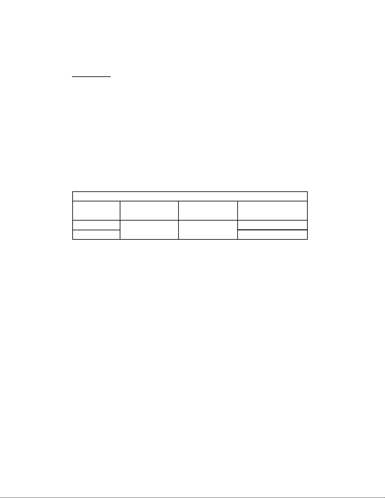
GasType BTU/Hr(kW)
perMainBurner
BTU/Hr(kW)
perSideBurner
ManifoldPressure
AllModels
Natural 4.0"WC(10.1cm)
Propane 10.0"WC(25.4cm)
20,000(5.86) 25,000(7.33)
GASINFORMATION