Magliner LiftPlus User manual

1-800-MAGLINE (624-5463)
LiftPlus®
1
Serial #: _________________________________
Date of Purchase: ________________________
LiftPlus®
Maintenance Manual

1-800-MAGLINE (624-5463)
LiftPlus®
2
Table of Contents
LiftPlus Toolkit........................................................................................................................................3
Safety Instructions.................................................................................................................................4
Removing Covers..................................................................................................................................5
Disconnecting/Connecting Battery ........................................................................................................6
Lift Screw Girdle and Upper Belt ...........................................................................................................7
Replacing Lower Belt.............................................................................................................................7
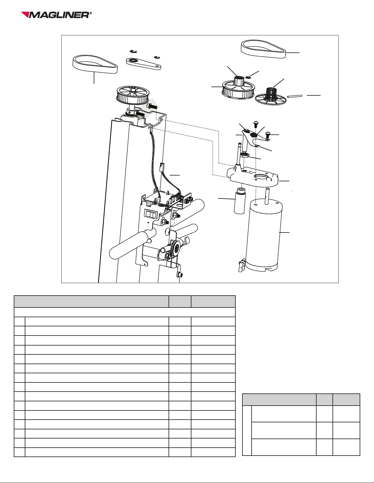
Motor Assembly.....................................................................................................................................8
Pulleys 1, 2-3.......................................................................................................................................10
Motor and Solenoid Body....................................................................................................................10
Motor Brake Pad .................................................................................................................................11
Lower Lift Screw Collar and Assembly................................................................................................13
Pulley 4................................................................................................................................................13
Lift Screw Thrust Bearing ....................................................................................................................14
Lift Screw Guide ..................................................................................................................................14
Trolley Assembly .................................................................................................................................16
Rear Rollers.........................................................................................................................................16
Front Rollers....................................................................................................................................... 17
Caster Assembly................................................................................................................................. 17
Disengaging/Engaging Brake Cable Ends ..........................................................................................19
Brake Cable Assembly ........................................................................................................................19
Brake Caliper Assembly ......................................................................................................................19
Adjusting the Brakes, Caliper ........................................................................................................ 20-21
Replacing Battery ................................................................................................................................22
Battery Box..........................................................................................................................................22
Circuit Breaker.....................................................................................................................................22
Lower Limit Switch...............................................................................................................................24
Upper Limit Switch...............................................................................................................................25
Power Switch; Up/Down Switch ..........................................................................................................26
Charging Light; Overload Light............................................................................................................26
Charging Input; Remote Control Input.................................................................................................27
Control Board Diagram.................................................................................................................. 28-29
Maintenance........................................................................................................................................30
Troubleshooting Guide ........................................................................................................................31
Advanced Troubleshooting Guide ................................................................................................. 32-34
Replacement Parts List ................................................................................................................. 54-56
Inspection / Maintenance Checklist................................................................................................ 57-63

1-800-MAGLINE (624-5463)
LiftPlus®
3
• Standard Allen wrench set
• #1, #2 Phillips head screwdrivers
•Large at head screwdriver
•Micro at head screwdriver
• Standard socket wrench set
• Metric socket wrench set
• Standard combination wrench set
• Long handled magnetic driver with assorted Phillips and hex heads
• Crescent wrench
• Vise-grips
• Channel-lock pliers
• Dead blow hammer
• 1 lbs. hammer
• Needle Nose Pliers
• E-ring tool
• Pin punch set
• Wire stripper
• Wire cutter
• Wire crimper
• Cordless drill
• Drill bit set
• Blue thread locker
• Anti-static wrist strap
LiftPlus Toolkit

1-800-MAGLINE (624-5463)
LiftPlus®
4
Maintenance/Repair Safety Instructions
•Wear safety glasses when performing maintenance or repairs.
•Always use the correct tool type and size required for the job.
•Be careful not to cause cosmetic blemishes while working on the LiftPlus.
•Be careful not to strip or cross thread any fasteners especially in aluminum parts.
•Be careful not to damage any wire insulation.
•Engage the parking brake before working on the liftplus unless you will be working on the
brake system.
•Do not Wear loose clothing, drawstrings, etc.
•Do not Use excessive force in any operation.
•Do not work on or around the drive or electrical components of the LiftPlus unless the
power switch is off and the battery is disconnected.
•Do not activate the motor unless all hands and tools are clear of the drive system.
•Do not disconnect wire connectors by pulling on their wires. Grip only the connectors
themselves.
•Do not contact the components of the control board with any metal tool.
•All replacements must be made with genuine Magliner parts.
General Safety Instructions
•Inspect before each use for damaged and loose fasteners/connections.
•Inspect the unit for cracks, wear or damage. Replace damaged components immediately.
•Keep hands and feet away from all moving parts.
•Never stand or sit on the work bench.
•Do not use this product to lift or to transport people.
•Never use as a step ladder.
•Never use on a moving vehicle.
•Never operate when any of the housing components have been removed.
•Keep all loose items away from the lift screw, as they may become entangled during use.
•Never use or store in wet environments or get any of the unit wet. The unit may be used
indoors or outside, but always use caution to keep the unit from getting wet; dry as soon as
possible.
•Never exceed 350 lbs. capacity. Damage to the lift and personal injury could result.
•Never raise or lower the work bench unless the unit is unfolded and the folding latch is
locked.
•Use extreme care when raising or lowering in close proximity to other objects. Hands
and other items may get pinched or injured as the moving attachment passes non-moving
objects.
•Never place a load’s center of gravity over the vise or work bench nose; always keep the
load center of gravity centered on the work bench.
•Never tilt the unit back with a raised load.
•Always check that the brakes are working correctly before operating with a load.
•Never walk away from the unit when the folding latch is in an unlocked position.
•Always keep the power switch off when the unit is folded.
•Never go over a curb or any other multi-level transition with a raised load.
•Do not operate when the battery charger is plugged in.
•Never attempt to open the battery. If the battery is cracked or leaking, do not recharge it - it
must be replaced.
•Always use a Magliner battery charger to charge your battery.

1-800-MAGLINE (624-5463)
LiftPlus®
5
REMOVING COVERS
TOOLS NEEDED:
5/64” ALLEN WRENCH OR HEX DRIVER (BRAKE COVER)
7/64” ALLEN WRENCH OR HEX DRIVER (MOTOR COVER & TOP COVER)
Item Qty. Part Number
A Button head cap screw - #6-32 x 5/16” long 4 80360
B Brake cover 1 533506
C Button head cap screw - #6-32 x 5/8” long 2 80359
D Motor cover 1 533505
E Top cover 1 533502
F Battery cover 1 533501
A
B
Brake Cover Motor Cover/Top Cover
Note: when replacing the motor cover, move any protruding wires of the electrical assembly so they will be contained within the
cover; make sure the bottom tabs slip under the protruding tabs of the electrical mount plate.
If the brake cover is installed, slide the motor cover down so that the bottom tabs slip inside the brake cover and under the pro-
truding tabs of the electrical mount plate.
C
D
E
Fold the LiftPlus; pull latch tab on
top of the cover and slide down.
Battery Cover
F

1-800-MAGLINE (624-5463)
LiftPlus®
6
LIFT DRIVE SYSTEM
DISCONNECTING/RECONNECTING BATTERY (disconnecting the battery is required for several processes in
this manual)
TOOLS NEEDED: NONE
1. Disconnecting the battery.
a. Fold the LiftPlus and remove battery cover.
b. Remove connectors off the positive and negative terminals.
c. Unfold and lock the LiftPlus.
2. Disconnecting the battery.
a. Fold the LiftPlus.
b. Slide the connectors onto the positive and negative terminals.
c. Install the battery cover; unfold and lock the LiftPlus.
Item Qty. Part Number
A Lift screw girdle 1 531115
B Belt 2 534118
C E-ring for 1/4” dia. shaft 1 221011
D E-ring for 3/8” dia. shaft 1 221012
A
B
D
C

1-800-MAGLINE (624-5463)
LiftPlus®
7
LIFT SCREW GIRDLE AND UPPER BELT
TOOLS NEEDED: NEEDLE-NOSED PLIERS OR E-RING TOOL; LARGE FLAT SCREWDRIVER; DEAD-BLOW
HAMMER
Removal:
1. Turn off the LiftPlus and disconnect the battery.
2. Remove motor and top covers.
3. Remove the E-rings from the top of the Pulley shaft and lift screw
4. Remove the lift screw girdle. If necessary insert a large at blade screwdriver between the lift screw girdle and
the top of either Pulley and gently twist.
5. Remove the upper belt by lifting it over the top of Pulley 2-3 while slowly turning Pulley 1 by hand.
Installation:
1. Turn off the LiftPlus and disconnect the battery.
2. Wrap the upper belt around Pulley 4 and stretch it just over the top of Pulley 2-3.
3. Press the belt down over Pulley 2-3 while turning Pulley 1 by hand.
4. Install the lift screw girdle, tapping gently with a dead-blow hammer if necessary.
5. Connect the battery unless other work on the lift drive system is planned.
REPLACING LOWER BELT
TOOLS NEEDED: NONE
Removal:
1. Turn off the LiftPlus and disconnect the battery.
2. Remove the lift screw girdle and upper belt.
3. Lift the Lower Belt over the top of Pulley 1 while slowly rotating Pulley 1.
4. Slide the lower belt out between Pulley 2-3 and Pully 4
Installation:
1. Turn off the LiftPlus and disconnect the battery.
2. Slide the lower belt in between Pulley 2-3 and Pulley 4.
3. Wrap the lower belt around the bottom of Pulley 2-3 and stretch it just over the top of Pulley 1.
4. Press the belt down over Pulley 1, while hand turning Pulley 1.
5. Install the lift screw girdle and upper belt.
6. Connect the battery unless other work on the lift drive system is planned.

1-800-MAGLINE (624-5463)
LiftPlus®
8
LIFT DRIVE SYSTEM (CONT.)
Item Qty. Part Number
Complete motor assembly includes:
A Motor - 12V DC 1 63024
B Solenoid and plunger assembly 1 63026
C Pulley 1 assembly 1 534106
D Pulley 2-3 assembly 1 534107
E Motor mount assembly 1 534102
F Motor brake lever 1 534111
G Motor brake pad 1 534112
H Flanged bushing - .250 ID x .375 OD x .38” long 2 534115
I Belt 2 534118
J Slotted spring pin - 1/2 x 1.5” long 1 81166
K Phillips head truss screw - #10-32 x .5” long 2 80348
L Flat washer - #10 2 80767
M Flat nylon washer - 3/8” 3 80766
N External ring - 7/16” 2 221014
O E-ring - 1/4” 2 221011
F
E
G
Item Qty. Part No.
P
Solenoid adapter
harness - 48” models
1 534421
Solenoid adapter
harness - 60” models
1 534422
Solenoid adapter
harness - 72” models
1 534423
Complete motor assembly also includes:
Motor Assembly Part No.:
48” models - 534100
60” models - 534100-60
72” models - 534100-72
K, L
B
B
B
A
D
C
H
I
I
O
M, N
J
P

1-800-MAGLINE (624-5463)
LiftPlus®
9
MOTOR ASSEMBLY
TOOLS NEEDED: 3/16” MAGNETIC HEX DRIVER OR ALLEN WRENCH
Removal:
1. Turn off the LiftPlus and disconnect the battery.
2. Remove lift screw girdle and upper belt.
3. Disconnect the motor and solenoid wires from rest of the electrical assembly by pulling apart the mating
connectors. Do not pull on the wires themselves! If the connectors are difcult to separate try working them
loose with gentle twisting and rocking.
4. Remove one of the motor mount screws with a 3/16” magnetic hex driver or Allen wrench.
5. Hold the motor with one hand and pull gently outward while unscrewing the remaining motor mount screw.
Installation:
1. Turn off the LiftPlus and disconnect the battery.
2. Hold the motor mount against the column ensuring that all wires needed to connect the motor and solenoid
are accessible.
3. Be sure that the grommet to protect the upper limit switch wires is secure in its slot in the column. The motor
mount traps this grommet in place.
4. Install the two motor mount screws (with lock washers) using a 3/16” magnetic hex driver or Allen wrench.
5. Connect the motor and solenoid wires to their mating wires.
6. Install the lift screw girdle and upper belt.
7. Connect the battery unless other work on the lift drive system is planned.
Pulley 2-3 ASSEMBLY
TOOLS NEEDED: NEEDLE-NOSED PLIERS OR E-RING TOOL
Removal:
1. Turn off the LiftPlus and disconnect the battery.
2. Remove the motor assembly.
3. Remove the .25” E-ring on the pulley post.
4. Slide the Pulley 2-3 assembly off the post.
5. Remove the bronze bushings from the pulley.
Installation:
1. Turn off the LiftPlus and disconnect the battery.
2. Check to be sure that the pulley anges are securely welded to the Pulley.
3. Install the anged bronze bushings in either end of the Pulley 2-3 assembly.
4. Slide the Pulley 2-3 assembly onto the pulley post.
5. Install the .25” E-ring onto the pulley post in the lower groove.
6. Install the motor assembly.
Pulley 1 ASSEMBLY
TOOLS NEEDED: 1-2 lb. HAMMER; 1/8” PIN PUNCH
Note: excessive force can damage the Pulley or the Motor shaft. Be sure that you have the correct size
punch and align and support everything carefully.
Removal:
1. Turn off the LiftPlus and disconnect the battery.
2. Remove the motor assembly.
3. Place the motor assembly on a hard, at, and stable surface with one of the long at sides of the motor mount
facing down.
4. Align Pulley 1 so that the split roll pin is vertical.
5. Using a 1/8” pin punch and a 1-2lb hammer drive the pin through until it clears the motor shaft.

1-800-MAGLINE (624-5463)
LiftPlus®
10
6. Use careful steady blows, and:
a. Stop frequently to check the alignment of pin and punch.
b. Do not overdrive the pin
c. Be careful not to damage the pulley with a misaligned punch.
Installation:
1. Turn off the LiftPlus and disconnect the battery.
2. Slide the Pulley 1 onto the motor shaft.
3. Carefully align the holes in the motor shaft and Pulley 1 so that both are vertical.
4. Push a 1/8” by 1.5” long split roll pin into the top of the slot in Pulley 1.
5. Place the motor assembly on a hard, at, and stable surface with one of the long at sides of the motor mount
facing down.
6. Using a 1-2lb-hammer deliver gentle blows to the pin until it enters the hole in the motor shaft.
7. Using a 1/8” pin punch and a 1-2lb hammer continue to dive the pin until it is fully engaged with the slot on
Pulley 1.
a. Use careful, steady blows.
b. Stop frequently to check the alignment of pin and punch.
c. Do not over drive the pin.
d. Be careful not to damage the Pulley with a misaligned punch.
8. Install the motor assembly.
MOTOR
TOOLS NEEDED: #2 OR #3 PHILLIPS SCREWDRIVER
Removal:
1. Turn off the LiftPlus and disconnect the battery.
2. Remove the motor assembly.
3. Remove Pulley 1
4. Unscrew the screws holding the motor to the motor mount and remove the motor.
5. Slide the Pulley 2-3 assembly off the post.
Installation:
1. Turn power switch off and disconnect the battery.
2. Install the motor onto the motor mount, being careful to trap the motor brake lever under the lock washers.
3. Make sure that the washers are not deforming the motor brake lever and that the solenoid plunger and motor
brake lever have free range of motion.
4. Install Pulley 1.
5. Install the motor assembly onto the LiftPlus
SOLENOID BODY
TOOLS NEEDED: MINIATURE FLAT SCREWDRIVER, CHANNEL-LOCK PLIERS (optional), BLUE
THREADLOCKER
Removal:
1. Turn off the LiftPlus and disconnect the battery.
2. Remove the motor cover.
3. Remove the motor assembly.
4. Grip the solenoid body with a pair of channel-locks and twist if from right to left to loosen it.
5. Insert a small at-blade screwdriver between the solenoid hex nut and the motor mount to prevent the nut
from spinning.

1-800-MAGLINE (624-5463)
LiftPlus®
11
6. Continue to turn the solenoid body by hand or with the channel-locks until it becomes free.
7. Remove the solenoid body and hex nut from the motor assembly.
Installation:
1. Turn power switch off and disconnect the battery.
2. Coat the threads of the solenoid body with blue thread locker.
3. Insert the solenoid body up through the hole in the motor mount.
4. Hand turn the hex nut onto the solenoid body as far as possible.
5. Insert a small at-blade screwdriver between the solenoid hex nut and the motor mount to prevent the nut from
spinning.
6. Turn the solenoid counterclockwise from the bottom until it is snug against the motor mount.
7. Connect the solenoid wires to the mating connector in the electrical assembly
8. Connect the battery unless other work on the lift drive system is planned.
MOTOR BRAKE PAD
TOOLS NEEDED: NEEDLE-NOSE VISE-GRIPS OR PLIERS
Removal:
1. Turn off the LiftPlus and disconnect the battery.
2. Remove the motor cover.
3. Grip the motor brake pad with a pair of needle nose vise-grips or pliers.
4. Hold the motor brake lever rmly against the motor mount with one hand.
5. Pull the motor brake pad straight upward until it pops free.
Installation:
1. Turn off the LiftPlus and disconnect the battery.
2. Insert the motor brake pad between the Pulley 1 and motor break lever so that the curve of the pad follows the
curve of the pulley and the nipples of the pad protrude through the holes in the motor brake lever.
3. Using a small pair of needle nose vise-grips or pliers grasp the nipples and pull them down until they pop
though the motor brake lever.
4. Install the motor cover.
5. Connect the battery unless other work on the lift drive system is planned.

1-800-MAGLINE (624-5463)
LiftPlus®
12
Item Qty. Part Number
A Spring pin - 3/16” dia. x 1-5/8” long 1 81167
B Spring pin - 3/16” dia. x 1” long 1 81168
C Upper lift screw collar 1 531113
D Thrust washer for 1/2” shaft 2 80796
E Lift screw thrust bearing 1 531114
F Guide bushing 1 80814
G Lower lift screw collar 1 531116
vClevis pin with groove - 3/4” long
(5/8” usable length) and E-ring 1 81165
Item Qty. Part Number
Lift screw - 48” 1 531102
Lift screw - 60” 1 531105
Lift screw - 72” 1 531107
LIFT DRIVE SYSTEM (CONT.)
A
B
C
D
E
F
HG

1-800-MAGLINE (624-5463)
LiftPlus®
13
LOWER LIFT SCREW COLLAR
TOOLS NEEDED: NEEDLE-NOSE PLIERS OR E-RING TOOL
Removal:
1. Drive the quick change latch to its lowest position.
2. Turn off the LiftPlus and fold the unit.
3. Remove the retaining ring on the clevis pin, then the clevis pin from the lower lift screw collar.
4. Slide the collar off of the lift screw.
Installation:
1. Slide the lower lift screw collar
2. Install the clevis pin and retaining ring.
3. Unfold and lock the LiftPlus.
LOWER LIFT SCREW ASSEMBLY
TOOLS NEEDED: NONE
Removal:
1. Remove the lower lift screw collar.
2. Disconnect the battery.
3. Unfold and lock the LiftPlus
4. Remove lift screw girdle and upper belt.
5. Hand-turn Pulley 4 counterclockwise until lift screw is free of trolley drive nut.
6. Pull lift screw assembly up and out of the column. It may be necessary to tap the bottom of the lift screw with a
hammer to free the assembly from the column.
Installation:
1. Turn off the LiftPlus and disconnect the battery.
2. Slide the lift screw assembly down into the plastic guide in the column.
3. Hand turn Pulley 4 clockwise until the trolley begins to lift the platform.
4. Align the lift screw guide bushing with the opening at the top of the column and press it in. A dead-blow ham-
mer may used on the top of the lift screw, but be sure that the bushing is correctly aligned before every blow.
5. Install the lift screw girdle and upper belt.
6. Check to be sure that the guide has not slid out of the bottom of the column. If it has it must be slid back and
held in place by hand to avoid damage while folding the LiftPlus.
7. Fold the LiftPlus
8. Install the lower lift screw collar.
9. Connect the battery unless other work on the lift drive system is planned.
10. Unfold and lock the LiftPlus.
Pulley 4
TOOLS NEEDED: 1-2 LBS. HAMMER, 3/16” PIN PUNCH
Removal:
1. Turn off the LiftPlus and disconnect the battery.
2. Slide Pulley 4 onto the lift screw.
3. Carefully align the holes in the lift screw and Pulley 4 so that both are vertical.
4. Push a 3/16” by 1.625” long split roll pin into the top of the slot in Pulley 4.
5. Place the lift screw assembly on a hard, at, and stable surface with Pulley 4 protruding just past the edge.
<OR>
Place the lift screw assembly on the oor with a block supporting the lift screw just below Pulley 4.

1-800-MAGLINE (624-5463)
LiftPlus®
14
6. Using a 1-2lb-hammer deliver gentle blows to the pin until it begins to enter the hole in the Lift screw.
7. Continue to drive the pin until the top of the pin is level with the edge of Pulley 4.
8. Drive the pin, using a 3/16” pin punch and a 1-2 lb hammer until it is fully engaged with the slot on Pulley 4.
a. Use careful steady blows.
b. Stop frequently to check the alignment of pin and punch.
c. Do not over drive the pin.
d. Be careful no to damage the Pulley with a misaligned punch.
9. Install the lift screw assembly onto the LiftPlus.
LIFT SCREW THRUST BEARING
TOOLS NEEDED: 1-2 LBS. HAMMER, 3/16” PIN PUNCH
Removal:
1. Turn off the LiftPlus and disconnect the battery.
2. Remove the lift screw assembly.
3. Remove Pulley 4.
4. Align the lift screw collar so that the split roll pin is vertical.
5. Using a 3/16” pin punch and a 1-2lb hammer drive the pin though until it clears the lift screw, but remains in
the lift screw collar.
6. Use careful steady blows.
7. Stop frequently to check the alignment of pin and punch.
8. Slide the lift screw collar off of the lift screw.
9. Slide the lift screw thrust bearing and attending washers off of the lift screw.
Installation:
1. Turn off the LiftPlus and disconnect the battery.
2. Slide the lift screw thrust bearing sandwiched between the two lift screw thrust bearing washers onto of the lift
screw.
3. Slide the lift screw collar with split roll pin partially installed onto the lift screw.
4. Carefully align the holes in the lift screw and lift screw collar so that both are vertical.
5. Push a 3/16” by 1.625” long split roll pin into the top of the slot in Pulley 4.
6. Using a 1-2 lb hammer deliver gentle blows to the pin until it begins to enter the hole in the Lift screw.
7. Continue to drive the pin until the top of the pin is level with the lift screw collar
8. Install Pulley 4 Install the lift screw assembly onto the LiftPlus.
GUIDE
TOOLS NEEDED: NONE
Removal:
1. Remove lift screw assembly.
2. Remove guide (it may be necessary to push the guide up from the bottom until it can be grasped and pulled
out the top).
Installation:
1. Slide guide into column.
2. Install the lift screw assembly.

1-800-MAGLINE (624-5463)
LiftPlus®
15
Item Qty. Part Number
A Nut, trolley drive 1 531705
B Trolley assembly 1 531700
C Rear roller 4 531709
D Axle for rear roller 2 22146
E Front roller 2 531708
F E-ring - 3/8” 2 221012
Quick change latch
assembly - 536034
B
A
C
D
F
E

1-800-MAGLINE (624-5463)
LiftPlus®
16
TROLLEY ASSEMBLY
TOOLS NEEDED: #1 PHILLIPS SCREWDRIVER
Removal:
1. Drive the trolley up to the upper limit switch.
2. Engage the parking brake; fold the LiftPlus.
3. Turn power switch off and disconnect the battery.
4. Remove the lower lift screw collar.
5. Remove lift screw girdle and upper belt.
6. Using a #1 Phillips driver remove upper limit switch leaving it connected to the wires.
7. Pull lift screw assembly up until trolley becomes free and remove the trolley and trolley drive nut
8. Gently slide the lift screw back to rest.
Installation:
1. Pull the lift screw out until at least 9” of thread are exposed
2. Press trolley assembly against it so that the trolley drive nut engages the threads of the lift screw
3. Slide the lift screw back down into the column so that the trolley and drive nut slide back into their track.
4. Align the lift screw guide bushing with the opening at the top of the column and press it in. (A dead-blow
hammer may used on the top of the lift screw, but be sure that the bushing is correctly aligned before every
blow.
5. Install the lift screw girdle and upper belt.
6. Hand turn pulley 4 counter-clockwise until the trolley clears the upper limit switch mounting area.
7. Replace the upper limit switch, checking that connections are secure, sleeving is in place and wires are
undamaged.
8. Check to be sure that the guide has not slid out of the bottom of the column. If it has it must be slid back and
held in place by hand to avoid damage while folding the LiftPlus.
9. Fold the LiftPlus
10. Install the lower lift screw collar.
11. Connect the battery.
12. Partially unfold the LiftPlus until it is 15-20° from vertical.
13. Turn on power; drive the trolley down to the lower limit switch.
14. Fully unfold and lock the LiftPlus.
REAR ROLLERS
TOOLS NEEDED: NONE
Removal:
1. Remove the top cover and upper limit switch.
2. Remove the motor assembly.
3. Slide the quick change latch up until the rear rollers clear the top of the column.
4. Slide the outer rear rollers off of the rear roller axles.
5. Slide one of the rear roller axles out of the side plate.
6. Remove the inner rear rollers and quick change latch.
Installation:
1. Remove all rear rollers and one rear roller axle from the platform assembly.
2. Hold the platform assembly at the top of the column with the top of the side plates straddling the lift screw
below the Pulley 4.
3. Install the rear rollers onto the installed rear roller axle.
4. Hold the remaining inner rear roller in place the remaining rear roller axle though the side plate and into the
roller.
5. Install the last rear roller.
6. Slide the rear rollers into the column and lower the quick change latch.
7. Install the motor assembly and the upper limit switch. Install the top cover.

1-800-MAGLINE (624-5463)
LiftPlus®
17
FRONT ROLLERS
TOOLS NEEDED: NEEDLE-NOSE PLIERS OR E-RING TOOL
Removal:
1. Rotate the quick change latch upward to expose the front rollers.
2. Remove the e-ring that retains the front roller.
3. Remove the front roller form the front axle.
Installation:
1. Slide the front roller onto the front axle.
2. Install the .375” E-ring onto the front axle.
Item Qty. Part Number
A Caster shell - RH 1 532504
B Caster shell - LH 1 532503
C Caster assembly with plate 1 532500
D Lock nut with nylon insert - 5/6”-24 1 80606
E Screw - 5/16”-24 x 2” long 1 80346
FLock nut - M6 1 80612
G Split lock washer - M6 1 80794
H Screw - M6 x 20mm long 1 80362
Quantities listed are for one
arm of the LiftPlus.
CASTER ASSEMBLY
D
B
A
C
E
F
G
H
TOOLS NEEDED: 1/2” WRENCHES; PHILLIPS SCREWDRIVER; 10M SOCKET WRENCH
Removal:
1. Remove screw and lock nut to remove caster assembly from the LiftPlus arm.
2. Remove the screw, lock nut and washer from the caster shells to release the caster from the shells.
Installation:
1. Slide the caster shells around the caster plate as shown. Slide the M10 screw through both shells and secure
with the washer and lock nut.
2. Slide the caster shells into the LiftPlus arm and secure with 2” long screw and lock nut.
Top “lip” of the caster shells t within
this groove for assembly.

1-800-MAGLINE (624-5463)
LiftPlus®
18
BRAKE SYSTEM
Cable assembly (must specify
14” or 25” chassis upon order)
Item Qty. Part Number
C Wheel assembly 1 532310
D E-ring - 1/2” 1 221009
E E-ring - 5/16” 2 221010
A, B
Quantities listed are per side of the LiftPlus.
Item Qty. Part Number
A Brake caliper, RH 1 532100R
B Brake caliper, LH 1 532100L
Part of cable assembly
C
D
E

1-800-MAGLINE (624-5463)
LiftPlus®
19
DISENGAGING/ENGAGING THE BRAKE CABLE ENDS
TOOLS NEEDED: VISE-GRIPS
Disengage:
1. Grip the adjustable cable crimps with a pair of vise-grips.
2. Loosen the setscrew using a hex driver or allen wrench.
3. Remove the adjustable cable crimps from the cable
4. Pull the cable through the holes in the brake arms.
Engage:
1. Remove the brake cover.
2. Pass the cable ends through the holes in the brake arms.
3. Install an adjustable cable crimp 2” form one end of the cable and secure it with a hex driver or allen wrench.
4. Squeeze both sets of brake arms and pull the free end of the cable taught, gripping it with a pair of vise-grips.
5. Install an adjustable cable crimp securely on the cable as close to the cable arm as possible.
BRAKE CABLE ASSEMBLY
TOOLS NEEDED: WIRE CUTTERS, 3/16” HEX DRIVER OR ALLEN WRENCH
Removal:
1. Remove the brake cover.
2. Disengage both ends of brake cable.
3. Cut the brake cable ties.
4. Loosen the cable mount retaining screw using a 3/16” hex driver or Allen wrench.
5. Remove cable mount.
6. Remove the brake cable assembly.
Installation:
1. Turn the brake adjustment screw counter clockwise until it no longer protrudes through the brake cable mount.
2. Slide the ferrules on middle ends of the cable housings into the holes on the bottom of the cable mount.
3. Place the cable mount against the bayonet and slide it under the retaining screw to that both washers are on
top of the cable mount.
4. Loop the middle of the cable over the brake balance pulley.
5. Tighten the cable mount retaining screw using a 3/16” hex driver or Allen wrench.
6. Engage the both cable ends with the brake arms.
7. Install new brake cable ties so that they pass between the column and bayonet and around each cable
housing. Install one 4-5” above the battery compartment and one level with the middle of the column handle.
8. Perform a brake adjustment.
9. Install the brake cover.
BRAKE CALIPER ASSEMBLY
TOOLS NEEDED: WIRE CUTTERS, 3/16” HEX DRIVER OR ALLEN WRENCH
Removal:
1. Disengage both ends of brake cable from the brake arms.
2. Disengage the brake arm springs from the brake arms and remove them.
3. Loosen the screw in the brake caliper assembly using a 3/16” hex driver or Allen wrench until it is free of the
nut in the inner brake arm.
4. Pull the screw out and catch the brake arms, brake ball keeper, and brake balls as they become free.
5. Remove the hubcap using a large at-blade screwdriver.
6. Remove the e-rings from the axle and the brake pad mounts.
7. Place blocking under the chassis on the side you are working.
8. Slide off the outer brake pad.

1-800-MAGLINE (624-5463)
LiftPlus®
20
9. Slide the rear wheel assembly off the axle.
10. Slide the inner brake pad and brake pad spacers off the mounts.
Installation:
1. Place blocking under the chassis on the side you are working.
2. Slide the inner brake pad and brake pad spacers onto the mounts.
3. Slide the rear wheel assembly onto the axle.
4. Slide on the outer brake pad.
5. Install the 1/2” e-ring onto the axle and the 5/16” e-rings onto the brake pad mounts.
6. Inspect replaced e-rings for secure t. Replace any that are loose.
7. Install the hubcap.
8. Assemble the brake arms, brake ball keeper, and brake balls and hold them inside the inner brake pad so the
center holes of all pieces line up and the pin in the outer brake arm ts into one of the small holes in the inner
brake pad.
9. Slide the .3125”-18 X 1.75” long Allen button head screw through from the outer brake pad to the inner brake
arm.
10. Tighten the screw into the brake caliper assembly using a 3/16” hex driver or Allen wrench until clamps the
brake pads on the brake rotor.
11. Back the screw off 1/2 turn.
12. Install the brake arm spring and engage it with the brake arms.
13. Engage both ends of the brake cable with the brake arms.
14. Perform brake adjustment procedures until brakes function properly.
Adjusting the Brakes
The brakes are adjusted at the factory, but should still be checked before every use. If the braking
power is insufcient, the brakes should be adjusted. Perform the adjustment on a dry, non-slippery
surface.
There are two forms of adjustment. One adjusts the brake cable tension and the other adjusts the
set of brake calipers. Adjusting the brake cable tension is usually sufcient. If you are unable to
achieve sufcient braking force by tightening the cable or if one wheel brakes more effectively than
the other, you may need to adjust the brake caliper.
Adjusting the Brake Cable Tension
1. Loosen the screw (1) that locks the brake cable mount using a 3/16” Allen wrench.
2. Adjust the tension in the cables by turning the brake adjustment screw (2) that protrudes from
the bottom of the brake cable mount using a 3/16” Allen wrench.
3. After adjusting the brake adjustment screw, re-tighten the locking screw.
4. To test the tension, squeeze the brake lever tightly, tilt the unit back about 35°, and push the unit
forward along the ground. The combined action should make the wheels skid on the ground.
5. If the wheels spin, the brakes are not adjusted correctly. If the cable is too tight, it may engage
the brakes when you are not pulling on the brake lever.
Other manuals for LiftPlus
3
Table of contents
Other Magliner Forklift manuals