Magma BERILL TM User manual

Translation of the original instructions
______________________________________________________________________________________________________________________________________________________________________________________________
OPERATION AND MAINTENANCE MANUAL
Heated display case BERILL TM
Revision 03
Revision date 19.06.2018

1
INTRODUCTION
The aim of the following guidelines is to inform a customer on how to operate, install, clean and maintain the
equipment.
Read these guidelines carefully before running the equipment. Keep this document as a permanent source of
information when operating the equipment and follow the corresponding instructions.
As a manufacturer, we are not responsible for any damage resulting from:
- Incorrect installation and/or operation;
- Making changes to the equipment without our written consent;
- Non-compliance with the established standards;
- Use of the equipment, inappropriate to its functional designation;
- Failure to follow the maintenance instructions;
- Use of non-original spare parts/accessories;
- Failure to follow the recommendations and instructions contained in this manual.
Notice:
All dimensions in drawings are given in mm, if not otherwise specified.
Illustrations may not fully correspond to the models shown in the guidelines.
CONTENTS
1. IMPORTANT NOTES..................................................................................................................... 2
2. SAFETY MEASURES..................................................................................................................... 3
3. GENERAL CHARACTERISTICS.................................................................................................... 4
4. STRUCTURE OF THE DISPLAY CASE......................................................................................... 5
5. DISPLAY CASE OPERATION........................................................................................................ 6
6. INSTALLATION AND MOUNTING................................................................................................. 8
7. OPERATION AND FOODSTUFF ALLOCATION…........................................................................ 10
8. MAINTENANCE AND CLEANING ................................................................................................. 12
9. LIGHTING....................................................................................................................................... 13
10. RECOMMENDATIONS ON THE TROUBLE-FREE FUNCTIONING OF THE DISPLAY CASE..... 13
11. ENVIRONMENTAL PROTECTION............................................................................................... 13
12. SPECIFIC CONDITIONS............................................................................................................... 13
13. WARRANTY FOR MATERIALS ................................................................................................. 13
Appendix A. ELECTRIC WIRING DIAGRAM BERILL TM 125……………………….………………… 14
Appendix B. ELECTRIC WIRING DIAGRAM BERILL TM 250………………………………………… 15
Appendix C.CHANGING THE OPERATING TEMPERATURE OF THE DISPLAY CASE…………. 16
Appendix D. THE LIST OF THE MAIN SETTINGS FOR THE ELIWELL ID 985 LX MANAGING
THE FUNCTION ING OF THE BERILL TM DISPLAY CASE……………………………………………..… 18
CE DECLARATION OF CONFORMITY.............................................................................................. 19

2
1. IMPORTANT NOTES
1.1 UNPACKING AND TRANSPORTATION
Make sure the package is intact. If it shows signs of improper handling or damage during
transportation, indicate this in the accompanying transport documents and immediately inform
the supplier.
The device is delivered on a wooden pallet adapted for operation by a hand cart or lift. Use
lifting devices that match the weight of the equipment.
All packaging materials are recyclable and must be disposed of in accordance with local
standards.
Do not press the side glass panels to move the display cabinet. They can break and cause
serious injuries.
1.2 INTENDED USE
This unit of furniture is intended for the storage and display of food products whose storage
temperature corresponds to the temperature range of the display case.
1.2 DEVELOPMENT AND STANDARDIZATION
This equipment has been designed and manufactured in accordance with the main
requirements of the European Low Voltage Directive (LVD) 2014/35/EU and the EU
Electromagnetic Compatibility Directive (EMC) 2014/30/EU, as well as in accordance with the
provisions of the standard EN 60335-2-49 – Household and similar electrical appliances -
Safety – Part 2 - 49: Particular requirements for commercial electric appliances for keeping
food and crockery warm.
The equipment has been developed and tested for compliance with environmental conditions of
climatic class 3 (25 oC - 60%). When using the display case in an environment that has a
different value from the above, the thermodynamic efficiency indicator may decrease and
energy consumption may increase slightly.

3
2. SAFETY MEASURES
2. CHILD SAFETY
Children should be supervised and not allowed to play with the device. Keep all packaging
materials, especially plastic ones, out of their reach.
2.2 GENERAL SAFETY RULES
This equipment was designed and manufactured in accordance with the requirements and
environmental conditions of climate class 3 (25 ° C - 60% ).
The equipment is not intended for use outdoors or in the rain.
Do not store explosive substances or objects, such as aerosol cans containing flammable
mixtures, inside this appliance.
ATTENTION: it is strictly forbidden to turn on the display case without grounding and move the
display case that is under voltage!
Make sure that both the supply voltage and the current corresponds to the parameters
indicated on the nameplate.
Prior to performing cleaning or maintenance the display case must be disconnected from the
electrical network.
During operation or after turning off the device, do not touch the heating elements and the
reservoir with heated water, as they can be very hot.
If the equipment ignites, turn it off and use a fire extinguisher, but only the powder type. Do not
use water to extinguish.

4
3. GENERAL CHARACTERISTICS
Technical data
Measurement
unit
Typical size
125
250
Climatic class
3 (25ºC / 60% Rh
Useful volume temperature
°
С
+60 / +85
Volume of the showcase
m³
0,8
1,6
Useful volume
m³
0,076
0,152
Electric data
Power supply
V/Hz
400 /3+N /50
Electrical equipment protection rate
code
IP 20
Max electrical power input Rated electricity input
W
3600
7100
Infrared lamps
W
3 x 300
6 x 300
Lighting
type
LED
Backlight power consumption
W
18
36
Rated power consumption per day
*1
Basic set of the cabinet (light-12h)
Basic set of the cabinet (light-24h)
kW*h
24.0
24,2
47,8
48,2
Water supply data
Heated water volume
m³
0,07
0,14
Water features
type
hot tap water
Pressure range
bar
0,1 – 10,0
Reservoir filling mode
type
automated
Connection:
- filling
- drain
- drainage piping system
type
G 1/2"
G 1/2"
D40
Dimensions
Overall dimensions:
length without side walls
length with side walls
width without side walls
width with side walls
height without side walls
height with side walls
mm
1250
1350
1090
1120
1180
1180
2500
2600
1090
1120
1180
1180
Weight without packaging
kg
240
395
*1- with a constant surrounding temperature of t 25°Сand a relative humidity 60%.
3.1 SECTIONS AND PLANS

5
4. STRUCTURE OF THE DISPLAY CASE
The display case represents a steamer display counter with two-zone controlled heating. The display case
consists of the following functional parts:
- water reservoir with electric heaters;
- upper thermal ceiling with ceramic heaters;
- upper lighting lampshade;
- water filling systems;
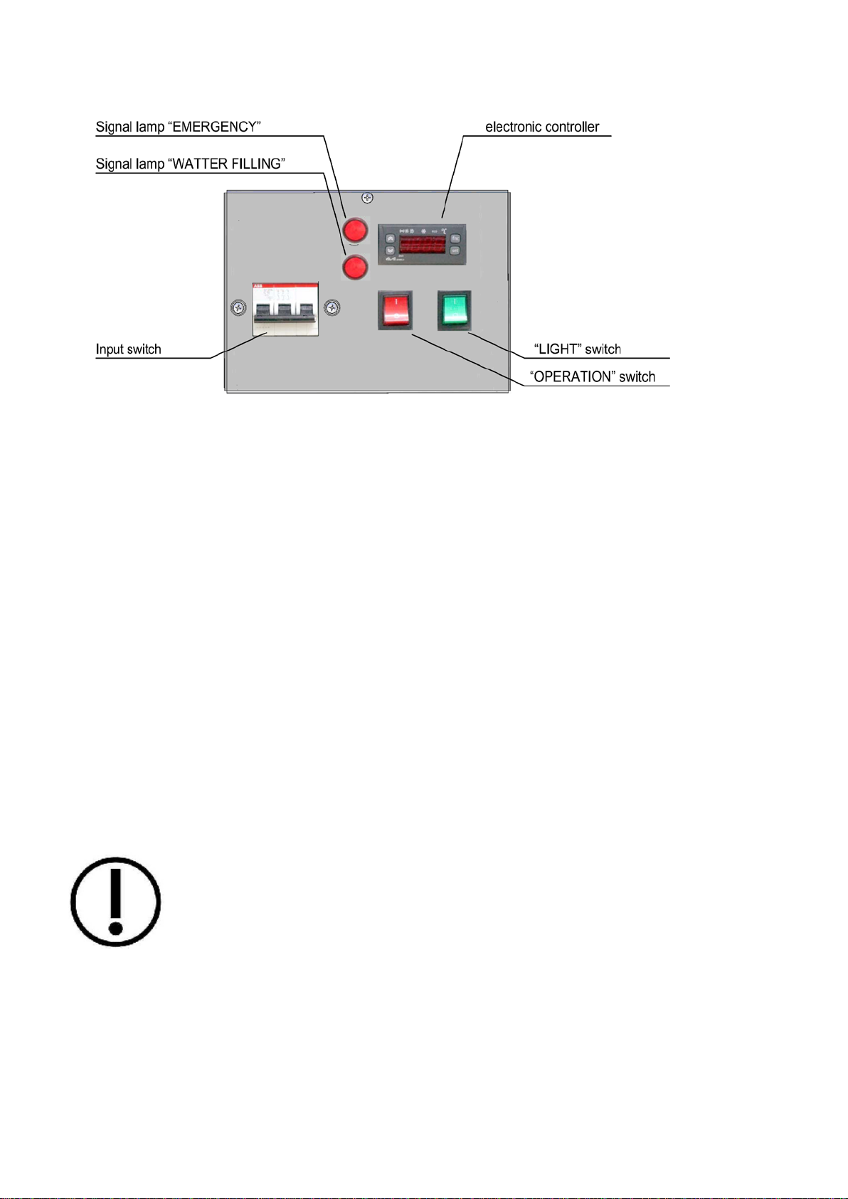
- control unit with electronic controller.
4.1 The water reservoir is equipped with:
- filling nozzle installed in the upper part of the reservoir, which is connected to the FILLING valve via an
electromagnetic valve (black color);
- a drain pipe installed in the bottom of the reservoir and connected to the DRAIN valve (red);
- overflow holes located above the level "MAXIMUM LEVEL" fixed by the water level sensor;
- a two-position water level sensor connected to an electronic controller and fixing the "MINIMUM LEVEL"
and "MAXIMUM LEVEL".
- steam temperature sensor installed in the upper part of the bath;
- tubular electric heating elements, the operation of which is controlled by an electronic controller using data
from a steam reservoir, temperature sensor and a water level sensor.
4.2 The upper thermal ceiling is equipped with ceramic Infrared heating elements, the operation of which is
controlled by an electronic controller using an upper volume temperature sensor. The heat lamp is powered
immediately as the display case is turned on.
4.3 The interior lighting of the case is carried out by LED lamps located in the upper lamp. The "LIGHTING"
switch is located on the front side of the display case control unit.
4.4 For the supply of cold water, a "FILLING" valve is installed on the case (black color). A "DRAIN" valve (red
color) serves to drain the water from the display case reservoir.
In case of an emergency overflow of the reservoir a drain pipe with a siphon connected to the sewer water
drainage pipeline is installed on the bottom of the display case. It removes the water trapped inside the display
case.
An electromagnetic valve is installed on the water-filling pipe to automatically replenish the water in the
reservoir. The operation of the solenoid valve is controlled by an electronic controller on the signal "MINIMUM
LEVEL" of the water level sensor.
4.5 The case is controlled by the electronic controller Eliwell ID 985 LX, located under the bottom on the seller's
side. It is configured to control heating and perform other functions of the display case.
A list of the main parameters of the controller responsible for the operation of the case is given in Appendix D.
Detailed information on how to program the controller is contained in the User Manual for the controller,
supplied with the showcase.
The electronic controller manages the following functions:
- maintaining the set temperatures in two zones (reservoir, upper space);
- automatic replenishment of water in the display case reservoir;
- alarming and operation in emergency situations.
To control the showcase, the following resources of the ID 985 LX controller are employed:
- to control the heating of the ceramic heating elements of the thermal ceiling (upper space), the resources
of the compressor control channel (compressor channel relay, Pb1 sensor) are used. The heating elements
of the ceiling are connected to the inverse output of the compressor channel;
- to control the heating of the heating elements of the water reservoir, the resources of the fan control
channel (fan channel relay, Pb2 sensor) are used. The heating elements of the water bath are connected to
a relay configured as a fan channel relay;
- the "MINIMUM LEVEL" sensor is connected to the digital input DI_1 (configured as a door relay (light
control));
- the "LEVEL MAXIMUM" sensor is connected to the digital input DI_2 (configured as an external fault);
- the water filling solenoid valve is connected to a relay configured as a "light" relay, in parallel with the
"WATER FILLING" signal lamp;
- the "EMERGENCY" alarm lamp is connected to a relay configured as an "Emergency" relay.
The electrical schematic diagram of the display case is given in Appendix A, B.

6
4.6 The location and purpose of the controls of the electronics unit is shown in figure
5. DISPLAY CASE OPERATION
The operation of the display case is controlled by an electronic controller managing heating
control, automatic replenishment of water in the reservoir, normal and emergency operations.
5.1 Heating control.
The management of the water heating in the reservoir is separate to the controls of the working
space of the display case.
Maintenance of the temperature level for the working space in a given range (from the value
"setpoint" (Setpoint) to the value "setpoint" +"differential" (Setpoint +"diF")) is carried out by
switching on/off the ceramic heating elements of the thermal ceiling.
Maintaining the temperature level of the water reservoir in a given range (from the value "FSt"-
"FAd" to the value "FSt" (folder "FAn")) is carried out by turning on/ off the water heating
elements.
At the "MINIMUM LEVEL" signal, the controller turns off the heating elements of the water
reservoir (“Fod“ parameter, "Fan" folder).
5.2 Automatic replenishment of water in the reservoir.
Automatic replenishment of the reservoir is carried out by opening the solenoid valve at the
signal of the sensor "MINIMUM LEVEL". The "WATER FILLING" warning lamp ignition defines
that the valve is open. After the deactivation of the "MINIMUM LEVEL" signal the closure of the
valve is not immediate. Closure delay may be set by the dLt parameter (the "Lit" folder).
Factory preset for the delay is 1 minute.
NOTE: SINCE THE CLOSING OF THE WATER FILLING VALVE OCCURS WITH ONE
MINUTE DELAY FROM THE "MINIMUM LEVEL" SIGNAL, IT IS REQUIRED TO CONTROL
THE OVERFLOW IN THE WATER RESERVOIR DURING THE DELAY TIMEFRAME.
OTHERWISE, TAKE MEASURES TO REDUCE THE INFLOW OF THE WATER.
5.3 Emergency modes of operation.
In case of an emergency, the display case controller issues an alarm signal, while the alarm
lamp "EMERGENCY" lights up on the front panel of the control unit and the buzzer signal turns
on.
The alarm signal is issued:
- when registering the signal "LEVEL MAXIMUM"
- when registering the signal "LEVEL MINIMUM" for more than 15 minutes
- when registering excess of emergency temperature thresholds, and sensor failures
- when registering a malfunction in the controller.

7
By issuing an "EMERGENCY" signal, the controller turns off the load relay for both bottom
heating and water filling.
By issuing an alarm signal, the controller records the mentioned events in the form of an
accident code. The accident codes are displayed on the controller's scoreboard. If there are
several codes, they can be viewed by scrolling Up and Down buttons.
E1 – sensor 1 Error (thermostat sensor Pb1 (upper space sensor))
E2 - sensor 2 Error (Pb2 sensor (reservoir sensor))
E3 - sensor 3 Error (sensor Pb3)
AH1 - Alarm upper limit (thermostat sensor control Pb1)
AL1 - Alarm lower limit (thermostat sensor control Pb1)
AH3 - Alarm upper limit (sensor Pb3)
AL3 - Alarm lower limit (sensor Pb3)
EA - External failure (signal registration " MAXIMUM LEVEL ")
E7 - LINK network error
E10 - Clock battery failure
Err - Controller memory corruption

8
6. INSTALLATION AND MOUNTING
This type of equipment should be installed and mounted by qualified and experienced
technicians.
6.1 IMPORTANT SAFETY INSTRUCTIONS
Please, follow these instructions while installing the cabinet:
•Personnel responsible for moving and installing equipment must have flexible and non-slip
work gloves, safety glasses, and safety shoes that must be used whenever necessary.
•Follow the instructions in the "Installation" section of the current manual and additional
guidelines, if applicable.
•Do not walk on the equipment.
•Do not install and use the equipment if it is damaged.
At installing the device near a wall, respect the distance of not less than 60 mm.
6.2 EQUIPMENT MOUNTING
Thoroughly remove any polyethylene film protecting the components and parts of the display
cabinet.
If this manual contains a Chapter with installation Instructions, follow the sequence indicated for
proper installation.
Align the display case in a horizontal position by adjusting the leveling feet to ensure:
•Proper operation;
•Smooth operation of water supply and water removal.
Use only hand tools to fix screws when mounting glass components and parts.
We recommend installing, if necessary, mechanical protection devices adapted to the
equipment to prevent possible damage, for example, from the impact of a trolley, a polisher, a
loader, etc.
6.3 DISPLAY CASE CONNECTION TO THE WATER SUPPLY
A plumbing flexible hose with G ½ nuts is employed to connect the display case to the water
supply system. Connect the hose to the black valve ( G½) installed on the filling pipe of the
showcase.
To drain the water from the showcase reservoir a "DRAIN" valve –red color- is installed on the
drain pipe (connection thread G ½).
The water drainage system of the display case designed to remove water, collected at the
bottom of the case, which may be formed due to steam condensation on the inner walls and/or
in case of an emergency overflow. The drain hole is located in the bottom of the display case. It
is equipped with a siphon (a siphon kit is attached to the case), which must be connected (D40
connection) to a sewer outlet
Note - the drain pipe laid over/under floors, should have a slight slope to facilitate runoff of the
water (about 2 degrees).
6.4 ADJUSTMENT OF THE FRONTAL GLASSES
Adjustment of the frontal glasses should ensure minimal and sufficient clearance between them
in 'lowered' and 'lifted' positions. A contact of glasses is unacceptable.
6.5 POWER SUPPLY CONNECTION
Make sure the voltage of the electric supply corresponds to the data specified on the nameplate
of the device. Deviations in the electric supply circuit voltage should not exceed ±10% from
those specified on the nameplate.

9
The equipment does not have any protection from overvoltage, so it is recommended to check
the safety level of the electric circuit to which the device will be connected to.
The device has a terminal for connecting with a potential equalization connector when it is
necessary to prevent the presence of voltage when touching between the grounding equipment
and metal parts that may accidentally come into contact with current-carrying electrical wires.
This terminal, marked with the corresponding symbol, is located in the electronics unit and is
intended for connection to the ground circuit with a wire with a cross section of 2.5-6 mm2.
Connect the equipment to the electrical network only at the end of installation.
6.6 DRY CHECK OF THE SHOWCASE'S OPERABILITY
After assembling and connecting the display case to the electrical network, it is necessary to
perform a dry check of its operability. Perform the following steps:
1. Apply voltage power to the display case.
2. Turn on the display case.
- While turning on, a click should be heard in the automation unit, which means a switching on
for the contactor of the upper heaters.
- After about a second, there should be a click from the opening of the electromagnetic water
filling valve, and the indicator lamp "WATER FILLING" should light up.
3. Check the heating of each heating element of the upper ceiling.
4. Turn on the light switch, make sure that the lighting lamps are lit.
5. The display of the electronic controller should show the temperature inside the case. (At the
moment, it will be the room temperature). On the front panel of the automation unit, the signal
lamp "WATER FILLING " is lit.
6. With your hand, move the float of the reservoir water level sensor to the middle and hold it in
such position. Immediately in the automation unit, a click should be heard from turning on the
contactor of the water heaters. And after 1 minute (the delay time is set up by the parameter
dLt = 1 (min) folder "Lit"), a click should be heard from the closing of the water filling
electromagnetic valve. While the warning lamp "WATER FILLING" should go out.
7. With your hand move the float of the water level sensor to the upper position. The buzzer
alarm should sound, and the "EMERGENCY" warning lamp should light up on the front panel of
the automation unit. A click from turning off the contactor of the water heaters should be heard
in the automation unit.
8. Turn off the display case.
Proper passing of all the above checks means that the showcase is in good condition.

10
7. OPERATION AND FOODSTUFF ALLOCATION
It is important to note that this equipment is not designed to increase the temperature of
products, but only to maintain the temperature at which they are stored
To optimize the operation of the equipment and keep the food in good condition, use only the
add-ons and accessories supplied with the display case.
the equipment is equipped with glass shutters, they need to be opened and closed carefully.
Do not use the roof of the display cabinet to store packing, spare parts and other materials.
7.1 PREPARING THE DISPLAY CASE FOR USE
Before using the display case, it is required to wash (clean) its inner and outer surfaces with a
detergent, see section 8 for recommendations on cleaning the display case.
Before cleaning, make sure that the display case is disconnected (the main switch of the
display case on the control panel is turned off, the switches "OPERATION" and "LIGHTING"
are fixed in the "OFF" position).
Avoid using abrasives and solvents that can damage the surface of the display case. Avoid
getting water and detergents on the parts of the display case that are under electric voltage.
It is recommended to wash the cleaned surfaces with clean water and wipe dry.
Lifting the front window of the showcase, lift it without jerks and with two hands, holding on to
the middle part until it locks in the upper position. Close the display case in the same way until
the front window is fixed in the lower position.
ATTENTION: IT IS UNACCEPTABLE TO LIFT UP (LOWER DOWN) THE FRONT GLASS
HOLDING ITS EDGE. THE EXCESSIVE EFFORT AND SKEWING OF THE GLASS MAY
OVERLOAD THE EDGE OF THE GLASS AND, AS A RESULT, DESTROY IT.
7.2 TURNING ON THE DISPLAY CASE
Turn on the display case only after carrying out all preparatory works fulfilled by qualified
personnel.
To turn on the showcase, do the following:
- apply the power to the display case by turning on the automatic switch on the display case
control panel;
- open the water supply tap in the case - the "FILLING" valve (black valve).
- turn on the toggle switches "OPERATION" and "LIGHTING" located on the control panel.
After a few seconds, the display case will turn on, the signal lamp "WATER FILLING" will
light up and the electromagnetic valve for automatic replenishment of water in the reservoir
will open up.
After filling the reservoir, the water filling electromagnetic valve will close and the "WATER
FILLING" warning lamp will go out, and the water heating will turn on.
After the temperature in the display case reaches the set values, the food staff can be loaded.
To turn off the display case, turn off the toggle switches "OPERATION" and "LIGHTING",
disconnect the case from the power net by turning off the automatic switch on the control panel,
close the "FILLING" valve, and drain the reservoir by opening the "DRAIN" valve (red valve).
ATTENTION: IF A BURNING SMELL APPEARS, THE OPERATION OF THE DISPLAY CASE
SHOULD BE STOPPED IMMEDIATELY, AND QUOLIFIED MAINTENANCE PERSONNEL
SHOULD BE CALLED TO ESTABLISH AND ELIMINATE THE CAUSE OF ITS ABNORMAL
OPERATION.
7.3 CONTROL AND ADJUSTMENT OF THE OPERATING TEMPERATURE
If the equipment is not connected to a central monitoring system with an alarm, you should
check the temperature value displayed on the controller screen several times a day, or at
regular intervals, in accordance with local regulations.

11
The digital display of the electronic controller mounted on the control panel of the electronics
unit and the mechanical thermometer mounted on the front panel of the showcase allow visual
control of the operating temperature. A digital display and a mechanical thermometer show the
value of the steam temperature in the display case tray.
The electronic controller manages Automatic control and maintaining of the operating
temperature within the specified limits.
The procedure for changing the operating temperature setting is given in Appendix C.
As a reminder, the controller has factory settings and their changes must be carried out by a
qualified specialist.
7.4 LOADING OF THE DISPLAY CASE
Loading the goods into the display case may begin when the operating space of the case
obtains required temperature.

12
8. MAINTENANCE AND CLEANING
Before cleaning disconnect power supply of the display case.
Maintenance and care of the display cabinet encourage sales, but most importantly it is a
safety measure to protect food products from microorganisms and bacteria and therefore the
customers’ health.
Good care and proper cleaning will establish a positive image of the seller.
8.1 CLEANING
Before cleaning or maintenance the equipment must be disconnected from the power supply to
guarantee the absence of an electric current in the system.
Do not use abrasive materials and substances or solvents, salt acids, detergents with chlorine
or pure spirit. Do not use metal or abrasive swabs for cleaning in order not to damage the
appearance and ensure a long service life of the equipment.
Clean the interior and exterior surfaces regularly with soft cloth, dampened with warm water
and a neutral chlorine-free detergent. Dry all water residues thoroughly using a sponge. To
clean the glass parts, use an appropriate liquid cleaner.
When washing the floors near the equipment, try to avoid accidental splashes onto the display
case – the chemical substances used for washing floors may fall on the equipment’s
components.
Notice: after cleaning foodstuffs must be loaded into the display case only once the inside
temperature reaches the defined values.
8.2 REGULAR MAINTENANCE
Before cleaning or maintenance the equipment must be disconnected from the power supply to
guarantee the absence of an electric current in the system.
Purpose of cleaning is to remove pathogenic microorganisms on external parts and interiors of
the case and to maintain physical appearance of the display case in a proper way.
Exterior parts of the showcase should be cleaned daily (weekly) with disinfectant compound.
The purpose of this cleaning is to emphasize the aesthetics of the appearance of the display
case, to remove pathogens on the outer parts of the case.
During the cleaning process, the outer parts of the display case should be washed with a
disinfectant detergent. Wash the treated surfaces thoroughly with clean water and wipe dry.
During the cleaning process, do not allow water and detergents to get on the parts of the
display case that are under electric voltage.
Clean interiors of the display case at least once a month to remove pathogens inside the
display area. For cleaning of the case use disinfectant detergents.
Before cleaning, all systems of the display case should be switched off, the display case
completely released from foodstuffs and the water drained. Wait until the temperature inside
the display case reaches room temperature.
To start cleaning - take out the food containers, wash them as well as the inner surface of the
display case with a disinfectant detergent. The cleaned surfaces should be thoroughly rinsed
with pure water and wiped dry.
After the cleaning is completed, all the removed parts must be installed back in the original
position and the display case must be turned on. As the temperature in the display case
reaches the set value, you can load it with foodstuffs.

13
9. LIGHTING
9.1 LIGHTING / LAMPS REPLACEMENT.
When replacing the lamps, disconnect the equipment from the power supply.
Any changes done to the electric grid must be performed only by an electrical engineer specialist.
In the case that this warning is violated, the company is not responsible of any damages incurred.
Please recycle used lamps in accordance to local regulations.
10 RECOMMENDATIONS ON THE TROUBLE-FREE FUNCTIONING OF THE DISPLAY CASE
In order to provide trouble-free functioning of the showcase it is recommended the following:
- control the temperature of the operating space of the showcase using the digital display of the electronic
controller;
- timely remove food residues fallen inside the display case;
- rinse the reservoir with heaters once a month, as a dirty rusty water leads to accelerated corrosion of heaters
and, as a result, to their destruction;
- inform the maintenance service specialist about the detected changes in the operation of the display case
(temperature change inside the case, abnormal fogging of glasses, etc.);
- monitor once a month the functioning of the display case involving the maintenance service specialist.
11. ENVIRONMENTAL PROTECTION
This equipment does not contain chlorofluorocarbons (CFC).
11.1 UNPACKING
All packing materials are recyclable and should be disposed of in compliance with local regulations.
11.2 END OF THE EQUIPMENT’S LIFE-CYCLE
At the end of a useful life of the equipment, we recommend the following:
• Make it unserviceable (for example, cut power cable)
• Remove glass shutters or other elements which may be dangerous for children or pets;
• Do not destroy the display cabinet.
The European Directive 2002/96/EC (WEEE) extends to this equipment, and it cannot be sent to a municipal
waste deposit and consequently must be delivered to a specialized point for electric and digital equipment
wastes collection to perform accurate recycling.
12. SPECIFIC CONDITIONS
Information in these guidelines is valid at the moment of printing. Nevertheless, under the conditions of
constantly developing technologies and product evolution, we reserve the right to change technical
characteristics and content of this document.
We are not responsible for alterations introduced by a consumer towards the equipment and non-compliance
with the recommendations and operating principles contained in this manual.
13. WARRANTY FOR MATERIALS
The components and parts of the display cabinet are covered by a 2-year warranty, starting from the date of
issue of the display cabinet, which is indicated on the nameplate.
The warranty does not cover consumable parts (lamps, starters for fluorescent lamps etc.).
Warranty service expires in the event of damage to the display cabinet due to improper use, violation of safety
rules or loss of the nameplate.

14
Appendix A. ELECTRIC WIRING DIAGRAM BERILL TM 125

15
Appendix B. ELECTRIC WIRING DIAGRAM BERILL TM 250

16
Appendix C. CHANGING THE OPERATING TEMPERATURE OF THE DISPLAY CASE
Operating temperature is set up by changing the value of the parameters in the display case controller:
- “FSt“ (pallet temperature);
- “Set“ (temperature of the display case upper space).
Note - The value of the “Set“ parameter must always be lower then that of the “FSt“ parameter to prevent
fogging of the front glass,.
To change the value of the “FSt“ parameter (upper place temperature) do the following:
Enter the Programming menu by pressing and holding the “set“ button of the controller for at least 5 seconds.
The label of the first menu folder “CP“ will appear on the display.
> 5 seconds
Use the “Up“ and “Down“ buttons to scroll through the programming menu folders until the “FAn“ folder
While on the folder label “FAn“, press the “set“ button
the first folder parameter will appear on the controller display.
Use the “Up“ and “Down“ buttons to switch to the “FSt“ parameter.
Press the “set“ button on the “Fst“ parameter and you will see its value.
Set the new temperature value by “Up“ and “Down“ buttons
Press the “fnc“ button
The entered parameter has been saved.
Turn off and turn on the display case again, now the case will work with the newly set value of the lower heating
temperature.
To change the value of the "Set" parameter (tray temperature), it is required the following:
Turn on the showcase. Press the “set“ button on the controller, “Set“ will be displayed on the scoreboard.

17
Press the “set“button on the “SEt“ parameter and you will see its value.
Using “Up“ and “Down“ buttons set the new temperature value
Press the “fnc“button.
The entered parameter has been saved.
Turn off and turn on the display case again, now the case will work with the newly set temperature value of the
upper space
Find below an example of a sequence of actions to change the value of the “FSt“ parameter from 60°C to 80° C
>5 seconds
Turn off and turn on the display case again.
Another example of a sequence of actions to change the value of the “SEt“ parameter from 60°C to 80° C
Turn off and turn on the display case again.

18
Appendix D
THE LIST OF THE MAIN SETTINGS FOR THE ELIWELL ID 985 LX MANAGING THE FUNCTION ING OF THE
BERILL TM DISPLAY CASE
Parameter
Description of the controller parameter
Parameter
value
Level
U.M/
Function
Set
Setpoint
+65°C
°С/°F
The upper heating temperature
COMPRESSOR SECTION (page labeled "CP")
diF
diFferential.
2,0
1
°С/°F
Differential activation of the upper heating relay
HSE Higher SEt. Maximum possible set point value. +85 1 °С/°F
The maximum possible set value of the upper
heating temperature
FANS (page labeled "FAn")
FSt
Fan Stop temperature.
65
1
°С/°F
Lower heating temperature
FAd FAn differential. 2,0 1 °С/°F
Differential activation of the lower heating relay
Fod Fan open door open. n 2 flag
Heating of the reservoir at the signal "MINIMUM
LEVEL"
ALARMS (page labeled "AL")
AFd
Alarm differential.
2,0
1
°С/°F
Differential activation of the alarm signal
HAL
Higher ALarm. Maximum alarm.
90,0
1
°С/°F
The value of the higher temperature limit
tdO time out door Open. 15 2 min
Delay in fixing the "ALARM" signal by the
"MINIMUM LEVEL" signal = 15 minutes
EAL
Blocking of regulators by an external alarm
y
2
flag
Controllers lock at "LEVEL MAX"
LIGHT AND DIGITAL INPUTS (page labeled "Lit")
dSd Light relay enable from door switch. y 2 flag
Turning on the water filling by the signal
"MINIMUM LEVEL"
dLt Light relay disabling (switch off) delay (cell light). 1 2 min
Delay in turning off the water filling by
deactivating the "MINIMUM LEVEL" signal
dOd Door switch switches off loads. n 2 flag
Block the upper heating by the signal "MINIMUM
LEVEL"
DISPLAY (page labeled "diS)"
ddd Selection of the value type to be displayed: 0 = Set point; 1 =
probe 1 (Pb1); 2 = probe 2 (Pb2); 3 = probe 3 (Pb3). 22 num
Indication on the device display:
1=temperature of the upper space
2= steam temperature in the reservoir
CONFIGURATION (page labeled "CnF")
H11
Configuration of digital inputs/polarity:
0 = disabled;
±1 = defrosting;
±2 = reduced set (SEt+OSP);
±3 = Auxiliary (AUX)
±4 = Door micro;
±5 = external alarm;
±6 = Disables storage of HACCP alarms (*only in HACCP models)
±7 = Standby (ON-OFF);
±8 = Maintenance request
4 2 num
Configuration of the digital input D.I.1 and its
polarity:
4 = sensor "MINIMUM LEVEL"
H12 Configuration of digital inputs/polarity. Same as H11 5 2 num Digital input configuration D.I.2 and its polarity: 5
= sensor "LEVEL MAX"
H21
Digital output configurability 2. (B)
0 = Disabled;
1 = Compressor;
2 = Defrost;
3 = Fans;
4 = Alarm;
5 = Auxiliary;
6 = Standby;
7 = Light;
8 = Buzzer
3 2 num BOutput configuration:
3 = water heating control
H22 Digital output configurability 1. (A) Same as H21. 1 2 num
AOutput configuration:
1 = upper heating control
H23 Digital output configurability 3. (С) Same as H21. 4 2 num
COutput configuration:
4 = "ALARM" signal output
H24 Digital output configurability 4. (В) Same as H21. 7 2 num
DOutput configuration
7 = output of the "WATER FILLING " signal
H25
Buzzer output configurability
0= disabled;
8= enabled (default):
1-7, 9-10= not used
8 2 num Buzzer Configuration
8=active

19
ДЕКЛАРАЦИЯ СООТВЕТСТВИЯ EC
EC Declaration of Conformity
Мы заявляем под нашу исключительную ответственность, что продукт:
We hereby certify under our exclusive responsibility that this product:
Витрина тепловая БЕРИЛЛ ТМ
BERILL TM Heated display case for commercial use
к которойотносится настоящая декларация, соответствует следующему стандарту:
to which this declaration refer, is in conformity with the following standard:
EN 60 335-2-49 - бытовые и аналогичные электрические приборы – безопасность -
Часть 2 - 49: особые требования к коммерческим электроприборам для поддержания тепла продуктов
питания и посуды.
EN 60335-2-49 - Household and similar electrical appliances - Safety -
Part 2 - 49: Particular requirements for commercial electric appliances for keeping food and crockery warm.
всоответствии сдирективами:
is in conformity with the Directives:
2014/30/EU (Electromagnetic Compatibility)
2014/35/EU (Low Voltage)
Kostroma, 2018-05-28
Avsiévitch V. A.
Generaldirektor
Note
The contents of this document are subject to change without notice
MAGMA Meliorativnaya str., 6, Kostroma,156961,Russian Federation
Tel./fax +007 (4942) 41-16-21 www.ks-rus.ru
Table of contents
Other Magma Commercial Food Equipment manuals
Popular Commercial Food Equipment manuals by other brands

Gastrodomus
Gastrodomus CL Instructions for use and maintenance

Henny Penny
Henny Penny Evolution Elite Gas 16X quick guide

Henny Penny
Henny Penny FlexFusion FPG-221 Service instructions

Structural Concepts
Structural Concepts ADDENDA 86772 user manual

Pitco
Pitco TB-SRTG14-2 Upgrade instructions

Backyard Pro
Backyard Pro Butcher Series instruction manual