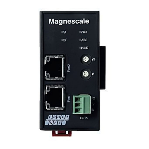
Magnescale MG80-EC User manual

MG80-EC
Operating Manual
EtherCAT Interface Module
Read all the instructions in the manual carefully before use and strictly follow them.
Keep the manual for future references.

MG80-EC

1
Contents
Contents ................................................................................................................................... 1
1. Introduction...................................................................................................................... 4
Features of EtherCAT.................................................................................................. 4
Communications Types of EtherCAT ........................................................................ 4
Configuration Elements of EtherCAT Network........................................................ 5
2. Basic Information............................................................................................................ 7
Equipment Used .......................................................................................................... 7
System configuration.................................................................................................. 8
3. Setting ................................................................................................................................ 9
Download of setting application and ESI file .................................................................. 9
About I/O data............................................................................................................. 9
Setting various parameters ....................................................................................... 9
3.3.1. Connection ............................................................................................................ 9
3.3.2. Setting method....................................................................................................11
3.3.3. Restart MG80-EC................................................................................................ 17
3.3.4. Starting EtherCAT Communications................................................................ 17
4. Specifications.................................................................................................................. 18
Interface specifications ............................................................................................ 18
LED indicator.............................................................................................................. 19
5. Function ........................................................................................................................... 21
Functions list.............................................................................................................. 21
Frame definition ........................................................................................................ 22
Detail of function....................................................................................................... 23
5.3.1. Peak hold............................................................................................................. 23
5.3.2. Pause.................................................................................................................... 24
5.3.3. Start ..................................................................................................................... 24
5.3.4. Reset .................................................................................................................... 24
5.3.5. Preset................................................................................................................... 24
5.3.6. Master preset...................................................................................................... 25
5.3.7. Comparator ......................................................................................................... 26
5.3.8. Add/Sub function ............................................................................................... 26
5.3.9. I/O module control ............................................................................................ 27
6. EtherCAT communication............................................................................................ 29
EtherCAT Communications Specifications............................................................. 29
Overview of EtherCAT .............................................................................................. 30

2
Communications Types of EtherCAT ...................................................................... 30
EtherCAT Communications Protocol (CoE) ........................................................... 31
Process Data Objects (PDO).................................................................................... 32
Service Data Object (SDO)...................................................................................... 32
EtherCAT Master Unit - Slave Unit Communications........................................... 33
EtherCAT Communications State Transitions ....................................................... 34
Emergency Messages ............................................................................................... 35
7. Details of Measurement Data .................................................................................... 36
Frame Measurement Value...................................................................................... 37
Counter Module Status............................................................................................. 37
Frame Comparator Result........................................................................................ 38
Frame Comparator Group Number ........................................................................ 38
Frame Output Type ................................................................................................... 39
I/O Module Input Signal........................................................................................... 39
I/O Module Output Signal ........................................................................................ 39
8. Appendix .......................................................................................................................... 40
Operation Parameters .............................................................................................. 40
Object Dictionary Structure..................................................................................... 43
Details of Object Dictionary..................................................................................... 46
8.3.1. Details of Communication Object Dictionary................................................. 48
8.3.2. Details of PDO Mapping Objects ...................................................................... 51
8.3.3. Sync Manager Communication Objects.......................................................... 65
8.3.4. Manufacturer Specific Objects ......................................................................... 67

3
Trademarks
EtherCAT®is registered trademark and patented technology, licensed by Beckhoff Automation
GmbH, Germany.
Microsoft®Windows®is the registered trademark of Microsoft Corporation.
Other system names, product names, and service names described in this manual are registered
trademarks or trademarks of the corresponding manufacturers.
Note that marks such as TM, ©, and ®are not noted in the text.
In no event will Magnescale Co., Ltd. or its suppliers be liable to you for
any consequential or inconsequential damages, including any lost profits
or lost savings or any claims made by a third party arising out of use of
the hardware system and its software described in this manual.
The specification of the product and its software may be changed without
prior notice.
This software has been confirmed to operate with Windows 10 version
20H2.
Operation is not guaranteed with regards to future Windows 10 updates.

4
1. Introduction
EtherCAT (Ethernet Control Automation Technology) is a high-performance industrial
network system based on Ethernet system and realizes faster and more efficient
communications.
Each node achieves a short communications cycle time by transmitting Ethernet
frames at high speed.
Furthermore, even though EtherCAT is a unique protocol, it utilizes standard Ethernet
technology for the physical layer, which provides excellent general-purpose
applicability such as the ability to use Ethernet cables. This enables to fully utilize the
effectiveness of EtherCAT not only in large control systems that require high
processing speeds and system integrity, but also in small and medium control
systems.
Features of EtherCAT
Extremely high-speed communications with speed of 100 Mbps
It dramatically shortens the I/O response time from generation of input signals to
transmission of output signals. By fully utilizing the optimized Ethernet frame
bandwidth to transfer data using a high-speed repeat method, it is possible to
efficiently transmit a wide variety of data.
Extremely High Compatibility with Ethernet
EtherCAT is an open network with extremely high compatibility with conventional
Ethernet systems.
Communications Types of EtherCAT
EtherCAT provides the following two types of communication functions.
Process data communications functions (PDO communications)
This communication function is used to transfer process data in real time in a fixed-
cycle.
By mapping logical process data space to each node by the EtherCAT master unit, it
achieves fixed-cycle communications among the EtherCAT master unit and slave units.

5
Mailbox communications functions (SDO communications)
It refers to message communications.
At any timing, the EtherCAT master unit transmits commands to slave units and the
slave units return responses to the EtherCAT master unit.
It performs the following data communications:
• Read and write process data
• Make slave unit setting
• Monitor slave unit state
PDO communications constantly update the data every communication cycle on
EtherCAT, and SDO communications are processed in between those updates.
Configuration Elements of EtherCAT Network
The overview of each configuration device is as follows:
EtherCAT master unit
Administers the EtherCAT network, monitors the state of slave units, exchanges I/O
data with slave units.
EtherCAT slave unit
Outputs data received from the EtherCAT master unit through the EtherCAT network,
or sends input data to the EtherCAT master unit through the EtherCAT network.
There are Digital I/O slave unit and Analog I/O slave unit. The MG80-EC is also
classified as a EtherCAT slave unit.
Configuration tool
It is a PC software for making setting of the EtherCAT network and each slave unit.
It can be used either by connecting to the EtherCAT master unit or as a substitute of
the EtherCAT master unit.
Communications cable
Uses cables of Ethernet category 5 (100BASE-TX) or higher, with double-shield
(aluminum tape and braided shielding), which are connected straight.
ESI (EtherCAT slave information) file
Describes information specific to EtherCAT Main modules in XML format unit.
You can make various setting such as the allocate slave unit process data by loading
file.

6
Unit power supply
Provides power for communications of each slave unit and internal operations.
Separate them from the I/O power supply when wiring.
I/O power supply
Provides power for input/output operations of external devices connected to slave
units.
Separate from unit power supply when wiring.

7
2. Basic Information
The MG80-EC is a communications slave unit that processes EtherCAT
communications between measuring units and a PLC to monitor the measured
values, write parameters, and operate the measuring units.
The PDOs in EtherCAT communications can be used to monitor the measurement
values without any programming. The SDOs provide the ability to read and write
to any specified parameter.
Equipment Used
The devices used when configuring a slave-side system with the MG80-EC are
shown below.
Name
Description
Image
MG80-EC EtherCAT interface unit
Main module
MG80-CM Counter module
DK800S
series
Measuring unit
DK805S/DK812S/DK830S
DK series Measuring unit
DK10/25/50/100
DT series
(via MT13)
Measuring unit
DT12/32/512

8
System configuration
The MG80-EC can be connected to a counter module MG80-CM for connecting a
measuring unit, and an I/O module LZ80-K1/K2 that can control the operation and
outputs of the constituent units using external signals.
• Connect the measuring unit DK series to the MG80-CM.
• Measuring unit numbers are assigned automatically starting from 1 in order from
the unit closest to the MG80-EC.
• For EtherNet/IP or Ethernet connection, prepare a shielded cable with a RJ-45
(8P8C) connector (straight connection).
Node address
SW=0×01
Node address
SW=0×02
Node address
SW=0×03
Node address
SW=0×04
EtherCAT or
Ethernet cable,
max. 20 m
(*) : Up to 16 MG80-CM can be
connected to each MG80-EC.
Upto two LZ80-K modules can
be connected within the unit.
LZ80-K1/K2
PC/PLC
Unit
EtherCAT
Interface Module
MG80-EC
Counter Module
MG80-CM

9
3. Setting
Download of setting application and ESI file
1. Access to Magnescale Web (https://www.magnescale.com)
「Products」
→「Digital Gauge」
→「Interface」
→「MG80-NE/EI/PN/EC MG80-CM」
→「Software」
Download the Setting application from “Setting application for Windows PC”
As above,
download the ESI file from “Setting file.”
The ESI file can be used regardless of the PLC manufacturer and the
number of axes used.
2. Save the file in an appropriate location and extract it with decompression
software.
About I/O data
When the ESI file is imported into the development environment, the I/O data is
handled as Byte array data. Please refer to “6. EtherCAT communication” for I/O
data mapping.
Setting various parameters
Various settings of MG80-EC can be performed from PC by using
“Setting application for Windows PC”
3.3.1. Connection
1. Preparation of "Setting application for Windows PC"
Please place the downloaded "MG80SettingTool.exe" file in an arbitrary
location.

10
2. Set the IP address and subnet mask of the PC on which the “Setting
application for Windows PC” was downloaded.
IP address :192.168.100. xxx※1
Subnet mask:255.255.255.0
※1 Address that cannot be set to XXX
・“1” that is used when setting with the MG80-EC.
・Same address as other connected devices.
3. Set the node address setting switch on the MG80-EC to “0x00” to enter the
setting mode and enable communication with the computer.
In this case, the IP address is fixed to the following.
IP address :192.168.100.1
Subnet mask:255.255.255.0
4. Connect the PC which “Setting application for Windows PC”” is installed and
MG80-EC directly with Ethernet cable. Connect the power supply and turn on
the MG80-EC.
* The “Setting application for Windows PC” can be used when connected to
either the IN side or OUT side port.
5. Click "MG80SettingTool.exe" on the PC on which "Setting application for
Windows PC " is installed to start the application.
Node address setting switch:0x00

11
3.3.2. Setting method
Set the various operation parameters using the “Setting application for Windows PC.”
When the “Setting application for Windows PC (MG80SettingTool.exe)” is started, the
following screen appears.
* The network settings are not used with the MG80-EC.
Network settings Connection
Parameter settings

12
Follow the steps below to connect to the setting application for Windows PC.
①Click the Start button at the top right of the setting application.
②Click the Connect button at the top right of the setting application.
③If the connection is successful, the network setting field and parameter setting
field become valid.
* If the connection fails, turn off the power of the MG80-EC and start again from the
setting application.

13
3.3.2.1.Measurement parameter setting
Check that the following parameter setting fields are active.
* If not, redo the connection procedure described in the previous section.
If there are multiple pages on each parameter screen, switch pages by cliking the
page forward buttons.
After setting the parameters on each parameter screen, click the “Set” button at the
bottom of the screen to send and save the parameters to MG80-EC.
Note) If you do not click the “Set” button, it will not be saved in MG80-EC, so
be sure to execute it on each screen.
By cliking the “Get” button at the bottom of each parameter screen, you can get the
parameters currently saved in MG80-EC.

14
Setting items
No Setting item
(Parameter name)
Contents
1 Axis
(Axis Setting)
Setting of input resolution, direction, reference point, and master preset value
for each axis.
2 Frame
(Frame Setting)
Addition and subtraction function, output mode, preset value setting for each
frame
3 Comp
(Comparator Setting)
Comparator threshold setting, number of step mode, setting of comparator
use group number for each frame.
4 I/O
(I/O Setting)
Function setting for each bit of I/O module input or output terminal
5 Other
(Other Setting)
Settings for items other than the above items.

15
(1) Axis Setting screen
(2) Frame Setting screen
Axis number Select from the pull-down
Input resolution:(0.1, 0.5, 1.0, 2.0, 5.0, 10.0μm)
Direction: Count direction of measuring unit (+, -)
Use Ref point: Valid or invalid of reference point (OFF: Not use;
ON: Use)
Reference point preset value (Unit: 0.1μm)
Frame number
Select from the pull-down
Ex.1: 1axis + 2axis Current value
Ope1(+), Main Axis No. (Axis1 val), Ope2(+), Sub Axis No. (Axis2 val), Mode (Real)
Ex.2: 3axis + 4axis Current value
Ope1(+), Main Axis No. (Axis3 val), Ope2(+), Sub Axis No. (Axis4 val), Mode (Real)
Preset value (Unit: 0.1μm)

16
(3) Comparator Setting screen
(4) I/O Setting screen
Group number of
comparator settings
Comparator setting
Use the spin button or the numeric keys to
enter the values.
(Unit: 0.1μm)
Step setting (2step/4step)
Select the group number
to be set in the selected
frame.
Select the frame to set
Input/output setting of the
first I/O module.
Select from the pull-down.
Input/output setting of the
second I/O module.
Select from the pull-down.

17
(5) Other Setting screen
3.3.3. Restart MG80-EC
1. After setting and saving all parameters, turn off the power.
2. Set the node address to be used in EtherCAT communications with the node
address setting switch on the MG80-EC.
3. Restart the power to operate with the set parameters.
3.3.4. Starting EtherCAT Communications
For the procedure for starting EtherCAT communications, refer to the manual of the
EtherCAT master unit.
Use the ESI file downloaded as described in “3.1 Download of setting application and
ESI file.”
Node address setting switch
Select the output unit of system.
Select from the pull-down.

18
4. Specifications
Interface specifications
Item
Specifications
Switch and
Indication
Switch Node address setting Setting switch×2 pcs. (Hexadecimal output 8bit)
Setting
value
0x00 Setting mode
IP address is fixed to 192.168.100.1
0x01
to
0xFF
Operates in Operation mode.
The node address is the setting value converted
to decimal notation. However, when 0xFF is set,
the node address is the value written in the
EEPROM inside the MG80-EC.
For the method of writing the node address
value, refer to the manual of
the EtherCAT
master unit.
Indication LED lamp status Refer to 4.2 LED indicator
Communi-
cation I/F
LAN connector RJ-45×2(100BASE-TX)
Shielded cable.
EtherCAT
communication
・Transmits the measurement values, error information, and
calculation results to the host device.
・Receives instructions such as operation parameter changes
from the host device.
・The communication standard is the EtherCAT standard.
TCP/IP communication ・When the node address setting switch is set to “0x00,” the
IP address is fixed to 192.168.100.1 and the mode becomes
the Setting mode for communication by TCP/IP.
In Setting mode, the operation parameters and IP address
can be set using the “Setting application for Windows PC.”
Power FG ×1
+V ×1
0V ×1
Terminal×1
(3 pole)
All modules and measuring units connected to MG80-EC are
supplied from this power supply terminal.
Table of contents
Other Magnescale Control Unit manuals