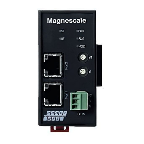
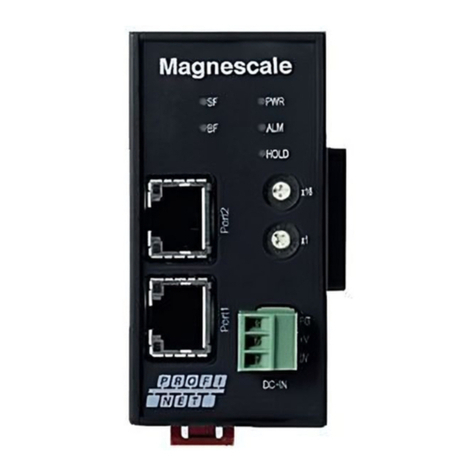
Magnescale MG80-SC1 User manual

MG80-SC1 / MG80-SC2
Operating Manual
RS-232C / Ethernet Interface Module
Read all the instructions in the manual carefully before use and strictly follow them.
Keep the manual for future references.

1/ 48
Contents
1Overview.........................................................................................................................................................3
2Configuration and Connections.......................................................................................................................4
2.1 Equipment Used.......................................................................................................................................4
2.2 System Configuration..............................................................................................................................5
2.2.1 Connection Example Using Command I/F over RS-232C (MG10 Replacement)...........................5
2.2.2 Connection Example Using Command I/F over Ethernet................................................................5
2.2.3 Connection Example over PLC Link (RS-232C).............................................................................6
2.2.4 Connection Example over PLC Link (Ethernet)..............................................................................6
3Name and Function of Each Part ....................................................................................................................7
4Installation.....................................................................................................................................................13
4.1 Connecting the Counter Modules ..........................................................................................................13
4.2 Installing the Unit on the DIN Rails......................................................................................................13
4.3 Removing the Unit from the DIN Rails.................................................................................................14
5Specifications................................................................................................................................................15
6Functions.......................................................................................................................................................16
6.1 Definition of Terms ...............................................................................................................................16
6.2 Details of Functions...............................................................................................................................16
6.2.1 Peak-hold........................................................................................................................................16
6.2.2 Preset..............................................................................................................................................16
6.2.3 Reference Point..............................................................................................................................17
6.2.4 Reset...............................................................................................................................................18
6.2.5 Start................................................................................................................................................18
6.2.6 Go/No Go Judgment (Comparator)................................................................................................18
6.2.7 Hold................................................................................................................................................19
6.2.8 Measurement Data Output .............................................................................................................20
6.2.9 I/O Connector.................................................................................................................................20
6.2.10 PLC Link Function.........................................................................................................................22
7Settings..........................................................................................................................................................26
7.1 When Upgrading from the MG10/MG10A ...........................................................................................26
7.2 Module Number Setting.........................................................................................................................26
7.3 Serial Port Setting (when Using RS-232C) ...........................................................................................26
7.4 Using the Setting Application to Configure the Settings.......................................................................27
7.4.1 Download the Setting Application.................................................................................................27
7.4.2 Connect ..........................................................................................................................................27
7.4.3 How to Configure the Settings.......................................................................................................28
7.4.4 Setting the Measurement Parameters.............................................................................................30
7.5 Using Commands to Configure the Settings..........................................................................................38

2/ 48
7.5.1 Preparation .....................................................................................................................................38
7.5.2 Connect ..........................................................................................................................................38
7.5.3 How to Configure the Settings.......................................................................................................38
8Commands ....................................................................................................................................................39
8.1 Communication Data Output Format.....................................................................................................39
8.2 How to Specify the Module Number and Counter Module ID..............................................................41
8.3 Setup Commands...................................................................................................................................42
8.4 Operation Commands............................................................................................................................44
8.5 Read Commands....................................................................................................................................45
8.6 PLC Link Setup Commands (Ethernet Only)........................................................................................46
9Troubleshooting............................................................................................................................................48

3/ 48
1Overview
This product is an RS-232C / Ethernet interface module for measuring systems that can acquire multi-axis measurement
data.
Because this product shares a common data format with existing MG10/10A products, MG10/10A users can continue to
use their programming environment with just a few settings changes.
In addition, the product has a PLC link function. By establishing a PLC link connection via RS-232C or Ethernet, it is
possible to send and receive data without preparing a communication program on the PLC side.
The MG80-SC can connect up to 16 MG80-CMs (counter modules).

4/ 48
2Configuration and Connections
2.1 Equipment Used
When configuring a system using this product, the equipment to be used is listed below.
Name
Description
Image
MG80-SC
RS-232C interface unit
Main module
MG80-CM
Counter module
DK800S series
Digital gauge
DK805S/DK812S/DK830S
DK series
Digital gauge DK10/25/50/100
DT series
(via MT13)
Digital gauge DT12/32/512

5/ 48
2.2 System Configuration
2.2.1 Connection Example Using Command I/F over RS-232C (MG10 Replacement)
RS-232C
Host PC
or
Digital gauge
Up to 16
MG80-CMs
MG80-SC Termination
PLC
2.2.2 Connection Example Using Command I/F over Ethernet
TCP or UDP
Host PC
or
Digital gauge
Up to 16
MG80-CMs
MG80-SC Termination
PLC

6/ 48
2.2.3 Connection Example over PLC Link (RS-232C)
RS-232C
Digital gauge
Up to 16
MG80-CMs
MG80-SC Termination
PLC link-compatible PLC
2.2.4 Connection Example over PLC Link (Ethernet)
Digital gauge
Up to 16
MG80-CMs
MG80-SC Termination
TCP or UDP
PLC link-compatible PLC

7/ 48
3Name and Function of Each Part
①Module number setting switch
Sets the module number. The various parameters of the MG80-SC can be configured using a user-assigned module
number.
The MG80-SC has an IP address of 192.168.0.100 and a subnet mask of 255.255.255.0 as default values, but the
settings can be changed. In the event the assigned IP address is forgotten, set the switch to 0xF to start up with the
default value.
②POWER lamp (PWR)
Indicates the operating status of this module.
Color
Status
Meaning
Green
Unlit
Power OFF
Lit
Measurement in progress with power ON
Blinking
Setup in progress with power ON
③ALARM lamp
Lights red when any counter module within the unit is in the alarm status.
Color
Status
Meaning
Red
Unlit
Normal status
Lit
An alarm is detected in one of the modules
④HOLD lamp
Lights orange when the hold function is activated in any counter module within the unit.
Color
Status
Meaning
Orange
Unlit
None of the counter modules are in the hold state
Lit
One of the counter modules is in the hold state
Blinking
When the reference point is used, one of the counter modules is in the reference point
wait state
⑤
⑥
⑧
④
⑩
③
①
⑦
⑨
⑫
②
⑪

8/ 48
⑤RS-232C connector
This is the PC/PLC connection port.
Use a DZ252 or DZ254 communication cable (sold separately).
When connecting to a PLC, be sure to match the terminal on the PLC side.
Compliant with EIA RS232C standard
Signals : Asynchronous, start-stop system, half-duplex system
Communication speed : 2400, 9600, 19200, 38400, 57600, 115200, 230400 bps
Data length : 7 or 8 bits
Parity : None, odd or even; selectable
Stop bit : 1 or 2 bits
Cable length : Max. 15 meters
Flow control: Hardware flow control (RTS, CTS)

9/ 48
DZ252 RS-232C cable
Round 8pin male ⇔Dsub 9pin female
Pin no.
Signal
(Signal GND)
(Request to send)
Case
Shield cable
Case
8pin mini DIN
9pin Dsub
Description
Host unit side
(Receive data)
(Transmit data)
(Clear to send)
Connection diagram
PIN No.
PIN No.
Pin description

10 / 48
DZ254 RS-232C cable
Round 8pin male ⇔bare wire
Pin no.
Cable color
Signal
1
Red
N.C
2
White
SG(0V)
3
Black
RXD
4
Yellow
TXD
5
Blue
CTS
6
Green
RTS
7
Brown
N.C
8
Gray
N.C
Case
Shield

11 / 48
⑥Ethernet port
This is the PC/PLC connection port.
Use commercially available Ethernet communication cables.
<Communication cable>
A CAT5e or higher shielded type is recommended.
Cable length: 20 m or less
⑦I/O connector
This I/O connector is used to operate all of the counter modules within the unit at once.
It has four input pins and one output pin.
MG80-SC1: Current sink type
MG80-SC2: Current source type
For details, refer to 6.2.9 I/O Connector.
⑧Power input connector
This connector is used to supply external power. (DC +12 to 24 V)
Description
Frame ground
DC +12 to 24 V
No.
Name

12 / 48
⑨RS-232C communication setting switch
Setting item
Setting contents
Switch no.
1
2
3
4
5
6
7
8
Delimiter
setting
CR+LF
-
OFF
-
-
-
-
-
-
CR
-
ON
-
-
-
-
-
-
Parity setting
OFF
-
-
OFF
OFF
-
-
-
-
ON Even
-
-
ON
OFF
-
-
-
-
ON Odd
-
-
ON
ON
-
-
-
-
Stop bit
1bit
-
-
-
-
OFF
-
-
-
2bit
-
-
-
-
ON
-
-
-
Data length
8
bit
-
-
-
-
-
OFF
-
-
7bit
-
-
-
-
-
ON
-
-
Communication
speed setting
2400 bps
OFF
-
-
-
-
-
OFF
OFF
9600 bps
OFF
-
-
-
-
-
ON
OFF
19200 bps
OFF
-
-
-
-
-
OFF
ON
38400 bps
OFF
-
-
-
-
-
ON
ON
57600 bps
ON
-
-
-
-
-
OFF
OFF
115200 bps
ON
-
-
-
-
-
ON
OFF
230400 bps
ON
-
-
-
-
-
OFF
ON
* Italic typeface is used to indicate the factory settings.
If you are using only the Ethernet port, keep the factory settings.
⑩Module connector
This is connected to the counter module.
⑪Termination module
This is the termination module. Connect to the endmost position of the unit.
⑫DIN rail anchoring lever
This lock mechanism secures the main unit to the DIN rails.

13 / 48
4Installation
4.1 Connecting the Counter Modules
Unlock the slide locks of the counter module to be connected.
Connect the connectors of the interface module and the counter module, and return the top and bottom slide locks to
the locked positions to secure the module.
4.2 Installing the Unit on the DIN Rails
This product supports 35 mm wide DIN rails.
When the interface unit is shipped from the factory, the tabs on the DIN rail anchoring levers are locked.
Align the top side of the groove in the unit’s rear panel with the top of the DIN rails, and install the unit by pushing it
into position until a clicking sound is heard so that the bottom side of the groove fits snugly on the DIN rails.
Un-
locked
Locked

14 / 48
4.3 Removing the Unit from the DIN Rails
While holding the unit in place so that it will not fall, pull down the DIN rail anchoring levers of all the modules until
a clicking sound is heard.

15 / 48
5Specifications
Model name
MG80-SC
Supply voltage
DC 10.8 to 26.4 V
Power consumption
2.4 W or less (not including the MG80-CM)
Maximum number of
connectable modules
MG80-CM: 16 modules*1
Power input socket
Terminal block×1 (3-pin)
Interface connector
RS-232C 8P×1
RJ45×1 (shielding compatible)
Communication protocol
RS-232C (2,400 bit/s to 230,400 bit/s)
Ethernet (100BASE-TX: 100 Mbit/s)
Maximum cable length
RS-232C: 15 m*2
Ethernet: 20 m (CAT5e shielded type recommended*3)
Module number setting
By rotary switch
Indicator lamps
Power: Green LED×1
Alarm: Red LED×1
Hold: Orange LED×1
Operating
temperature/humidity range
0 to +50°C (no condensation)
Storage temperature/humidity
range
–20 to +60°C (20 to 90% RH)
Mass
Approx. 130 g
Mounting method
DIN rail
*1 Up to 16 MG80-CM can be connected to each MG80-SC.
*2 Use a DZ252 or DZ254 RS-232C communication cable (sold separately).
*3 The customer must provide the Ethernet communication cables.

16 / 48
6Functions
6.1 Definition of Terms
Term
Definition
Current value
The value currently measured
Maximum (MAX)
value
The maximum measured value
Minimum (MIN) value
The minimum measured value
Peak-to-peak (P-P)
value
The value obtained by subtracting the minimum value from the maximum value
Output value mode
Current value mode, maximum (MAX) value mode, minimum (MIN) value mode and
peak-to-peak (P-P) mode
Measured value
A general term covering the current values, maximum values, minimum values and peak-
to-peak values
Peak value
A general term covering maximum values, minimum values and peak-to-peak values
(held in the main module)
Go/No Go judgment
output
The result obtained by comparing the upper and lower limits of the comparator with the
measured value
PLC link
Allows the unit to read and write PLC memory devices
6.2 Details of Functions
6.2.1 Peak-hold
The MG80-SC holds the peak values at all times.
The peak values are checked by switching among the output value modes.
The start function makes it possible to restart measurement from an optional position.
6.2.2 Preset
When the reference point is not used
When the preset value recall is supplied, the preset value that has been set is set to the current value.
When the reference point is used
In this case, the function uses the master preset value (refer to section 6.2.3).
When the master value is supplied as the preset value input after the reference point has been loaded for the first
time, the distance from the master value (preset value) to the reference point is calculated, and the reference point
offset value is generated internally and stored.
After the reference point has been loaded for the second and subsequent times, the reference point offset value is
automatically loaded, which means that the preset value need not be input for the second and subsequent times.

17 / 48
6.2.3 Reference Point
When the reference point is not used
After the power is turned on, the measuring state is established automatically. (Incremental operation)
When the reference point is used
After the power is turned on, the unit automatically enters the reference point signal input wait status. Once the
reference point is passed, the reference point position changes to 0 or the measurement from the offset value.
Incremental operation continues until the reference point is passed.
Note
This can be used only when using a measuring unit with a reference point.
[How to set the reference point]
1. Turn on the power.
The HOLD LED blinks if there is a module that has been configured to use the reference point.
2. Push the spindle of the measuring unit 1 mm or more, and retract it.
When this is done for all the modules that have been configured to use the reference point, the HOLD LED will
turn off.
3. Align the measuring unit with the master object to be measured.
4. Input the master value as the preset value using the setting commands.
Transmit the SETUP command, P command, then the CLOSE command, in this order. The reference point offset
value is stored in the counter module.
Once this value is set, the master value can be relocated after the power is next turned on when the spindle of the
measuring unit is pushed 1 mm or more.
To set the reference point again, clear the reference point offset value using the setting command (LCLR command),
and proceed again from step 1.
At least 1 mm

18 / 48
6.2.4 Reset
This function resets all the measured values to zero regardless of whether the preset value is set.
Note
・The reference point setting is also canceled when the reference point is being used. Set the reference point again.
・If a reset is supplied while the reference point is being set, the reference point setting is canceled at that time.
6.2.5 Start
Resets the peak value.
Measured value
Change in value
Current value
Remains unchanged
Maximum value
Sets the current value
Minimum value
Sets the current value
Peak-to-peak (P-P) value
Sets the value obtained by subtracting the
minimum value (zero) from the maximum
value
6.2.6 Go/No Go Judgment (Comparator)
This function judges “go” or “no go” for the measured values in the output value mode that is set. The Go/No Go
judgment results are added to the data and output by RS-232C or Ethernet.
The comparator values set the upper and lower limits. Up to four sets of comparator values can be set, and the set of
values used can be switched partway through the measurement.
Measured value
Judgment
Judgment output
Upper limit < measured value
Upper limit NG
U
Lower limit ≤ measured value ≤ upper limit
GO
G
Measured value < lower limit
Lower limit NG
L

19 / 48
6.2.7 Hold
The MG80-SC has two types of hold functions: latch and pause. They cannot be used at the same time.
Latch
In the current value mode, this function holds output data and comparator output for that value. When latched, the
current value will stop updating, so the peak value will also stop updating.
Pause
This function holds the peak value. Even if the current value exceeds the peak value, the peak value will not change.
This manual suits for next models
1
Table of contents
Other Magnescale Control Unit manuals
Popular Control Unit manuals by other brands

Samson
Samson BR 26l operating instructions

Triax
Triax CCAV 300 Assembly instruction

Infineon
Infineon AIROC CYW20822-P4TAI040 manual

VAT
VAT 570 Series Installation, operating, & maintenance instructions

Rohde & Schwarz
Rohde & Schwarz R&S RSC user manual

Pentair
Pentair Autotrol Performa 400 Series Service manual