Magnetek Elevator HPV1000 Series Guide

HPV1000-App_Note_27
HPV1000-App_Note_27
Closed Loop Start Guide
(Using the JVOP180 Keypad)
Guide to set up HPV1000 drive in Closed Loop Vf Control

HPV1000-App_Note_27
Closed Loop Start Guide
NOTE: This quick start-up guide just outlines the general parameters that should be changed / verified when a
drive is installed with information that are readily available. The drive will not run if only these parameters are set.
Because different controller manufacturers have different interfaces, it is recommended that the parameters in the
drive be set to what is recommended by the elevator controller in their technical manual.
Closed-Loop Operation Set-up
1) Enter / verify that the drive is set to run in Closed Loop Vector in the Drive Mode menu (Selection 0 in the A1-
02 menu).
Option Card
2) The drive will need an option card to run in closed loop mode. Confirm that the encoder board is installed in
the drive. The most common variant for closed loop induction is the PG-X3 card. The card should be installed
as follows:

HPV1000-App_Note_27
Closed Loop Start Guide
Encoder Wiring
3) The encoder should be wired to the drive as follows:
Table 1 CL: PG-X3 Encoder connections
•IP is the +VDC, and IG as the common.
•The encoder voltage is selected via the jumper CN3 as either 5.5V or 12V
•Note that the encoder is wired in to the upper case terminals. The lower case terminals are an output
from the drive and won’t necessarily be used.
•If wired single ended, PG Card Detect (F1-20) must be Disabled
Hoistway Parameter Set-up
4) Enter / verify the following parameters:
•CONTRACT CAR SPD (O1-25) parameter should be the lift contract speed in m/s. This can be verified
with a hand tachometer if required and adjusted if required.
•CONTRACT MTR SPD (O1-26) parameter should be set to the RPM that is required to make the lift travel
at contract car speed
NOTE: The above two parameters are utilised by the drive for many purposes regarding speed control of the lift,
therefore its important these are set correctly prior to continuing any further.
Input Voltage
5) Enter the Line Voltage:
•INPUT VOLTAGE (E1-01) parameter should be set to the measured incoming phase to phase
voltage.

HPV1000-App_Note_27
Closed Loop Start Guide
Encoder Set-up
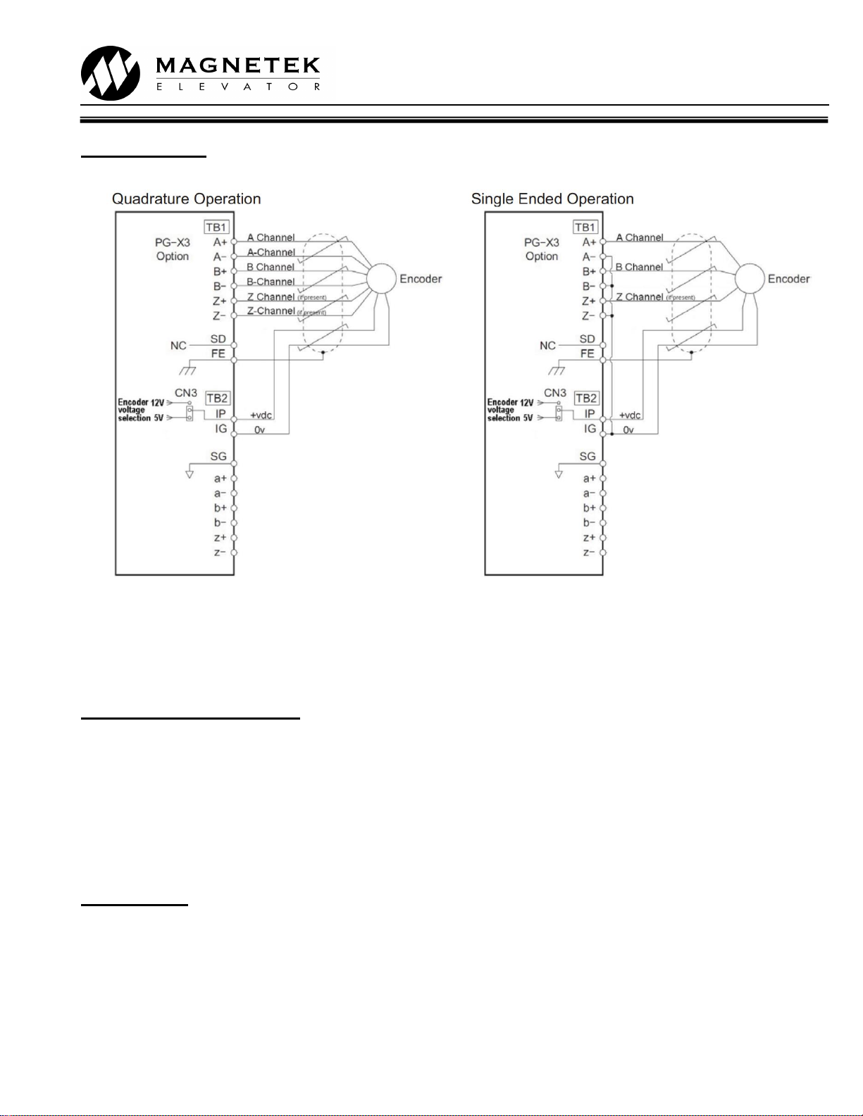
6) Verify the encoder has been selected and installed in accordance with the following:
Electrical interference and mechanical speed modulations are common problems that can result in improper
speed feedback getting to the drive. To help avoid these common problems, the following electrical and
mechanical considerations are suggested.
IMPORTANT- Proper encoder speed feedback is essential for a drive to provide proper motor control.
Electrical Considerations
•If possible, insulate both the encoder case and shaft from the motor.
•Use twisted pair cable with shield tied to chassis ground at drive end
•Use limited slew rate differential line drivers.
•Do not allow capacitors from internal encoder electronics to case.
•Do not exceed the operating specification of the encoder/drive.
•Use the proper encoder supply voltage and use the highest possible voltage available. (i.e. 12VDC is
preferred because less susceptible to noise)
Mechanical Considerations
•Use direct motor mounting without couplings where possible.
•Use hub or hollow shaft encoder with concentric motor stub shaft.
•If possible, use a mechanical protective cover for exposed encoders.
Autotune
7) The autotune can now be performed by navigating to the ‘T’menu. The drive has several options for
autotuning the motor, however usually the motor will be roped, and so the ‘Tune-No Rotate1’ (Static) method
will be used.
If the ropes are off, and the motor can turn freely, the ‘Standard Tune’ (Rotating) method can be used.
Navigate to the Autotune menu and enter the following information:
•‘Tune-No Rotate1’ (TUNING MODE SEL(T1-01))
•Motor Rated Power in kW (MTR RATED POWER(T1-02))
•Rated Voltage in V (RATED VOLTAGE(T1-03))
•Rated Current in A (RATED CURRENT(T1-04))
•Rated Frequency in Hz (RATED FREQUENCY (T1-05))
•Number of Poles (NUMBER OF POLES(T1-06))
•Rated Motor Speed* (RATED SPEED (T1-07)) - This is after slip, so NOT synchronous speed.
•Encoder Pulses (ENCODER PPR (T1-08))
•No Load Current (NO-LOAD CURRENT(T1-09) - Enter 35% of the RATED MOTOR CURRENT entered
above for 4 pole motors or 45% for a 6 pole motor
*Note The rated motor rpm entered must
equal what it can achieve at rated frequency,
at full load and full speed. If synchronous
speed is given on the dataplate, a lower RPM
must be entered. Table 2 gives an indication
of typical motor rated rpm for lift applications.
Once the above information has been entered and the bottom of the menu is reached the screen will display:
‘Auto-tuning. Waiting for command –Tune Ready? Give Run/Hit Enter’.
At this point DO NOT press any keypad buttons.
Synchronous
speed (50hz)
Rated motor
Speed (rpm)
Number of
motor poles
Typical No
Load Current
1500
1480 - 1340
4
35%
1000
980 - 840
6
45%
Table 2: Synchronous/Asynchronous Motor Speeds &
Motor Poles Reference for 50Hz

HPV1000-App_Note_27
Closed Loop Start Guide
Using your inspection controls, PRESS AND HOLD the buttons to run the lift in the UP DIRECTION (the lift
will not move, however the tune will begin) If the drive has control of the motor contactors they will now pull in
and the tune will begin.
During this process the drive will display motor speed and motor current for reference.
Once complete the drive will display “END Tune Successful”. The test run UP button can now be released.
The drive will then automatically populate the following parameters:
•Encoder Pulses (F1-01)
•Rated Mtr Power (E2-11)
•Rated Mtr Volts (E1-05)
•Rated Motor Freq (E1-04)
•Rated Motor Curr (E2-01)
•Number of Poles (E5-04)
•Motor Rated Slip (E2-02) –calculated from autotune
•No-Load Current (E2-03)
•Leak Inductance (E2-06) –calculated from autotune
•Term Resistance (E2-05) –calculated from autotune
Low speed inspection mode
8) Run the drive in low speed inspection mode and…
•Start with default value of 2 for INERTIA (P5-03)
•Verify encoder polarity. The motor phasing should match the encoder phasing. If you experience Speed
Dev Flt/ PGO Fault the phasing may be incorrect -this can be reversed changing ENCODER CONNECT
(F1-05) between Forwards and Reverse
•Verify proper hoistway direction. This can be reversed by changing both the MOTOR ROTATION (B1-14)
and ENCODER CONNECT(F1-20) parameters.
Key Drive Parameters
NOTE: Key parameters that are not listed below are parameters that are set for drive/controller interface:
Drive Menu
Parameter
Description
Default
Units
Suggested Adjustment
CONTRACT CAR SPD
O1-25
Elevator contract speed
2.0
m/s
Adjust to speed the installation is rated
to run at.
CONTRACT MTR SPD
O1-26
Motor speed at elevator contract speed
1450.0
rpm
Adjust this value to ensure the actual
running speed of the car matches the
parameter above. If the car is traveling
too fast then reduce this value, if too
slow then increase it.
RESPONSE
P5-02
Sensitivity of the speed regulator
10.0
rad/sec
Set to 20 to improve the drive response
to changes in speed reference. If the
motor current and speed becomes
unstable, reduce however if the value is
too small, the response will be sluggish.
INERTIA
P5-03
System inertia
2.00
sec
Determines the system inertia in terms
of the time it takes the elevator to
accelerate to contract speed. If the car
is light, the value will be smaller than the
default and vice versa if the car is
heavy.
ENCODER PULSES
F1-01
Encoder counts per revolution
1024
PPR
Obtain the Encoder PPR from the
encoder nameplate and enter in this
parameter.

HPV1000-App_Note_27
Closed Loop Start Guide
Parameter
Description
Default
Units
Suggested Adjustment
MTR TORQUE LIMIT
P5-08
This parameter sets the maximum
motoring torque the drive will produce in
the motor
200.0
%
Determines the maximum torque
allowed when in the motoring direction.
This is generally left at the default
setting. If the drive intermittently gives
‘Hit Torque Limit’ messages, this can be
increased. 250% would be a
recommended value.
REGEN TORQUE LIMIT
P5-09
This parameter sets the maximum
regenerating torque the drive will produce
in the motor
200
%
Determines the maximum torque
allowed when in the regenerating
direction. This is generally left at the
default setting. If the drive intermittently
gives ‘Hit Torque Limit’ messages, this
can be increased. 250% would be a
recommended value.
Table 3 CL: Important parameters in A1 menu to set/check when setting up a drive in closed-loop
Power Convert
Parameter
Description
Default
Units
Suggested Adjustment
INPUT VOLTAGE
E1-01
Nominal line-line AC
input Voltage, RMS
0
Volts AC
Adjust to match the voltage across R, S, and T of the drive.
The drive uses this value for its undervoltage alarm and fault
detection circuit
UV DETECT LEVEL
L2-05
DC Bus Voltage level
for undervoltage fault
500
Volts DC
Usually set to around 70% of the DC Bus voltage while idle
(Can be monitored in the D2 menu)
PWM FREQUENCY
C6-03
Carrier frequency
8
kHz
Setting this parameter to 8kHz is a good starting value to
ensure low motor noise. Increasing this value will derate the
drive.
Table 4 CL: Important parameters in A4 menu to set/check when setting up a drive in closed-loop
Motor
Parameter
Description
Default
Units
Suggested Adjustment
MTR RATED
POWER
E2-11
Rated motor output
power
0
kW
Set to motor kW rating as per the motor nameplate (Should be set
during autotune)
RATED MTR
VOLTS
E1-05
Rated Motor Voltage
0
VAC
Set to motor Voltage rating as per the motor nameplate (Should be
set during autotune)
RATED MOTOR
FREQ
E1-04
Rated excitation
frequency
0
Hz
Set to motor frequency rating as per the motor nameplate (Should be
set during autotune)
RATED MOTOR
CURR
E2-01
Rated motor current
0
Amps
Set to motor nameplate rated current (Should be set during autotune)
NUMBER OF
POLES
E2-04
Motor poles
4
none
Adjust to set number of motor poles (Should be set during autotune)
MOTOR RATED
SLIP
E2-02
The slip frequency of
the motor
0
Hz
Set to the slip frequency of the motor (Should be set during autotune)
NO-LOAD
CURRENT
E2-03
No Load Current
0
A
If it is not known, use the default value (Should be set during
autotune)
LEAK
INDUCTANCE
E2-06
Leakage Inductance
0
%
These parameters should be set during the autotune
TERM
RESISTANCE
E2-05
Phase to phase
resistance of motor
0
%
Table 5 CL: Important parameters in A5 menu to set/check when setting up a drive in closed-loop

HPV1000-App_Note_27
Closed Loop Start Guide
Basics
Parameter
Description
Default
Choices
Suggested Adjustment
DRIVE MODE
A1-02
Drive operation
Closed
Loop Vect
V/f Control
Open Loop Vector
Closed Loop Vector
PM ClosedLoop Vct
Set to Closed Loop Vect (Note: not “PM
ClosedLoop Vct”!) to run in Closed Loop mode.
Can be set to Open Loop Vect to run without
encoder feedback for diagnosis purposes
Table 6 CL: Important parameter in U8 menu to set/check when setting up a drive in closed-loop
This manual suits for next models
2
Table of contents
Other Magnetek Elevator DC Drive manuals
Popular DC Drive manuals by other brands

Rockwell Automation
Rockwell Automation Allen-Bradley 160-AA02 installation instructions

Danfoss
Danfoss VLT AQUA Drive FC 200 instruction manual

Sprint Electric
Sprint Electric 400 product manual

ABB
ABB Dodge HSCXT105 instructions

FAAC
FAAC S800H manual

LOVATO ELECTRIC
LOVATO ELECTRIC VLA1 series quick guide