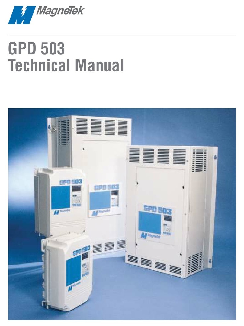
Magnetek GPD 315 User manual

GPD 315
Technical Manual
MagneTek

FACTORY USER
PARAMETERS SETTING SETTING
n0610
n0620.10
n0660
n0671.00
n068100
n0690
n0700
n071100
n0720
n0730.10
n074100
n0750
n0760.10
n0770
n0780
n07910
n0804
n0810
n0820
n0830.00
n0840.00
n0850.00
n0860.00
n08950
n0900.0
n0910.0
n0920
n093170
n094160
n0950.00
n0960
n0970
n098160
n0990.1
n1000
n1031.0
n104Note 2
n105Note 1
n106Note 1
n107Note 1
n108Note 1
n109150
n110Note 1
n111Note 2
n112Note 2
n1130
n1150
n1160
n1200.00
Note 1: Factory setting differs depending on GPD 315 capacity. See Appendix 3-1.
Note 2: Factory setting differs depending on control method selected (n002). See Appendix 3-1.
QUICK REFERENCE – – GPD 315 PARAMETERS
This list revised 10/99
MagneTe
k
FACTORY USER
PARAMETERS SETTING SETTING
n0011
n0020
n0031
n0042
n0050
n0060
n0070
n0080
n0090
n0100
n01160
n012230
n012460
n01360
n014Note 2
n015Note 2
n016Note 2
n017Note 2
n0180
n019
n020 10.00
n021 or
n022 10.0
n0230
n0246.00
n0250.00
n0260.00
n0270.00
n0280.00
n0290.00
n0300.00
n0310.00
n0326.00
n033100
n0340
n036Note 1
n0370
n0388
n0390
n0501 (1)
n0512 (2)
n0523 (0)
n0535 (5)
n0546 (6)
n0557 (7)
n05610 (10)
n0570
n0581
n0592
n060100
FACTORY USER
PARAMETERS SETTING SETTING
n1200.00
n1210.00
n1220.00
n1230.00
n1240.00
n1250.00
n1260.00
n1270.00
n1280
n12910
n1301.0
n1311.0
n1320.00
n1330
n134100
n1350.0
n1360
n1370
n1381.0
n1390
n140Note 1
n14150
n14212
n1431 (24 ms)
n1440%
n1450.5%
n1460.2%
n1493072(30,
720 Hz)
n1500
n1510
n1520
n1530
n1542
n1552
n15610
n1570
n158Note 1
n159120
n16016
n16110
n1625(20 ms)
n1631.0
n1640
n1750
n176rdy
n1770
n178N/A
n1790021N/A

- i -
Current Ratings & Horsepower Range
RATED CURRENT NOMINAL MODEL
INPUT RATING (AMPS) HORSEPOWER NO.
0.8 1/8 MVA001
1.6 1/4 MVA002
2 3.0 1/2 MVA003
3 5.0 3/4 & 1 MVA005
0 8.0 2 MVA008
V 11.0 3 MVA011
17.5 5 MVA017
25 7.5 MVA025
33 10 MVA033
1.2 1/2 MVB001
41.8 3/4 MVB002
63.4 1 & 2 MVB003
04.8 3 MVB005
V9.2 5 MVB009
14.8 7.5 MVA015
18 10 MVA018
WARNING
Do not touch circuit components until main input power has been turned
OFF. Status indicator LEDs and Digital Operator display will be extinguished
when the DC bus voltage is below 50 VDC. Wait at least one additional
minute.
Do not connect or disconnect wires and connectors while the main input
power is turned on.
CAUTION
The GPD 315 leaves the factory with parameters initialized for 2-Wire control
(when using external Run/Stop signals). Before using the initialization
function of constant
n001
, know your control wiring configuration:
8 = Factory 2-Wire Control Initialization (Maintained RUN Contact)
9 = Factory 3-Wire Control Initialization (Momentary START/STOP Contact)
Entering either Initialization code resets all parameters to factory settings,
and automatically returns parameter
n001
setting to “ 1 ”. If the GPD 315 is
connected for 3-Wire control and this parameter is set to “ 8 ” (2-Wire
Control Initialization), the motor may run in reverse direction WITHOUT A
RUN COMMAND APPLIED. Equipment damage or personal injury may
result.
Data subject to change without notice.

- ii -
CAUTION
Parameter
n012
must be set to proper motor voltage. Drive leaves factory
with this parameter set for “ 400 ” volts.
CAUTION
Always ground the GPD 315 using its ground terminal ( ) (near the main
circuit output terminals). See paragraph 1.4A, “Grounding”.
Never connect main circuit output terminals T1 (U), T2 (V) & T3 (W) to AC
main circuit power supply.
CAUTION
When drive is programmed for auto-restart ( n082 = " 1 " thru " 10 "), the
motor may restart unexpectedly — personal injury may result.
IMPORTANT
Wiring should be performed only by qualified personnel.
Always ground the GPD 315 using ground terminal ( ). See paragraph 1.4C, “Grounding”.
Verify that the rated voltage of the drive matches the voltage of the incoming power.
Never connect main circuit output terminals T1, T2, and T3 to AC main circuit power supply.
All parameters have been factory set. Do not change their settings unnecessarily.
Do not perform a “HIPOT” or withstand voltage test on any part of the GPD 315. Equipment uses
semi-conductors and is vulnerable to high voltage.
The Control PCB employs CMOS ICs which are easily damaged by static electricity. Use proper
electrostatic discharge (ESD) procedures when handling the Control PCB. Never touch the printed
control board (PCB) while the main input power is turned on.
Any modification of the product by the user is not the responsibility of MagneTek, and will void the
warranty.
Do not remove the Digital Operator or change dipswitch SW2 or rotary switch SW1 unless the main
input power is turned OFF.

QUICK REFERENCE FOR GPD 315 PARAMETERS ................Inside Cover
CURRENT RATINGS AND HORSEPOWER RANGE........................... i
WARNINGS & CAUTIONS .................................................................... i
1 RECEIVING / INSTALLATION ............................................................ 1-1
1.1 General ................................................................................................ 1-1
1.2 Receiving ............................................................................................. 1-1
1.3 Physical Installation ............................................................................. 1-1
1.4 Electrical Installation ............................................................................ 1-4
2 INITIAL START-UP ............................................................................. 2-1
2.1 Pre-Power Checks ............................................................................... 2-1
2.2 Open Loop Vector Startup ................................................................... 2-2
2.3 V/f Startup Procedure .......................................................................... 2-6
3 OPERATION AT LOAD ....................................................................... 3-1
4 DIGITAL OPERATOR .......................................................................... 4-1
4.1 General ................................................................................................ 4-1
4.2 Digital Operator ................................................................................... 4-1
4.3 Status Indicator LEDs .......................................................................... 4-3
4.4 Monitor Displays .................................................................................. 4-3
5 PROGRAMMABLE FEATURES ......................................................... 5-1
5.1 General ................................................................................................ 5-1
5.2 Accel/Decel Time ................................................................................. 5-2
5.3 Accel/Decel: S-Curve Characteristics .................................................. 5-3
5.4 Auto-Restart ......................................................................................... 5-4
5.5 Carrier Frequency ................................................................................ 5-5
5.6 Critical Frequency Rejection ................................................................ 5-6
5.7 DC Injection Braking ............................................................................ 5-7
5.8 Frequency Reference Bias/Gain (Analog) ........................................... 5-8
5.9 Frequency Reference Upper and Lower Limits ................................... 5-9
5.10 Frequency Reference Retention .......................................................... 5-9
5.11 Frequency Reference Selection ......................................................... 5-10
5.12 Jog Reference .................................................................................... 5-13
5.13 Local/Remote Reference and Sequence Selection ............................ 5-14
5.14 Modbus Control .................................................................................. 5-16
5.15 Miscellaneous Protective Functions ................................................... 5-20
5.16 Momentary Power Loss Ride-Thru ..................................................... 5-20
5.17 Multi-Function Analog Monitor Output (Term. AM and AC) ................ 5-20
5.18 Multi-Function Input Terminals (Term. S1-S7) .................................... 5-21
5.19 Multi-Function Output Terminals (Term. MA, MB, MC, P1, P2, PC) ... 5-27
5.20 Overtorque Detection ......................................................................... 5-30
- iii -
CONTENTS
SUBJECT
PARAGRAPH PAGE
Table of contents
Other Magnetek DC Drive manuals

Magnetek
Magnetek G+ User manual

Magnetek
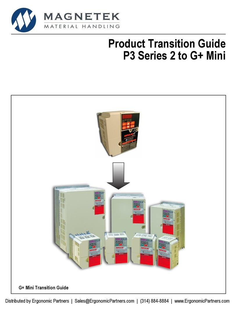
Magnetek IMPULSE G+ Mini User manual

Magnetek
Magnetek P3 Series User manual

Magnetek
Magnetek GPD 205 User manual

Magnetek
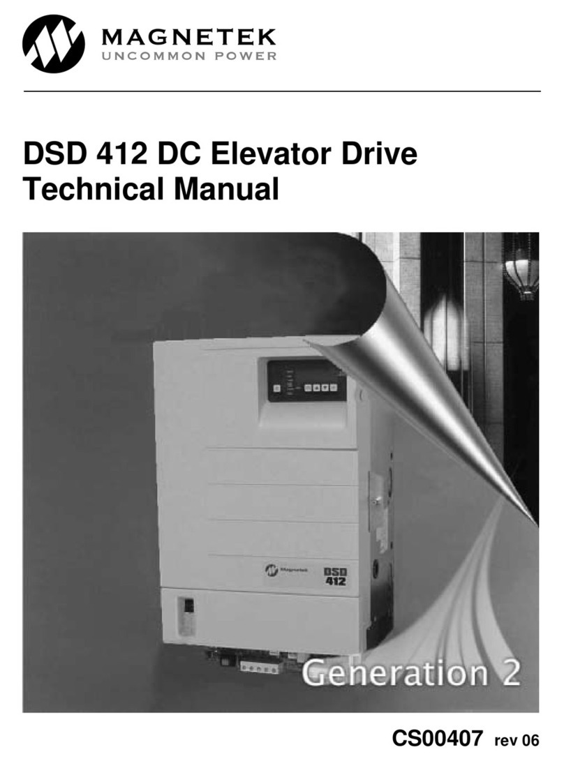
Magnetek DSD 412 User manual

Magnetek
Magnetek gpd 503 User manual

Magnetek
Magnetek GP1000 User manual

Magnetek
Magnetek Impulse G+ series 4 User manual

Magnetek
Magnetek HPV1000 Guide

Magnetek
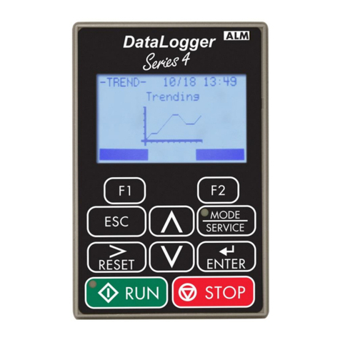
Magnetek DataLogger 4 Series User manual