Product Transition Guide
G+ Mini Rev:
G+ Mini Transition Guide September 2008
Page 4 of 24
Magnetek, Inc.
1.1 Overview
This purpose of this document is to provide an easy transition from the P3 Series 2 (N060 = 00) to the G+ Mini (A01.01 = 1).
For the advanced portion (A01.02 = 2), please refer to the G+ Mini Advanced instruction manual (P/N 144-25084).
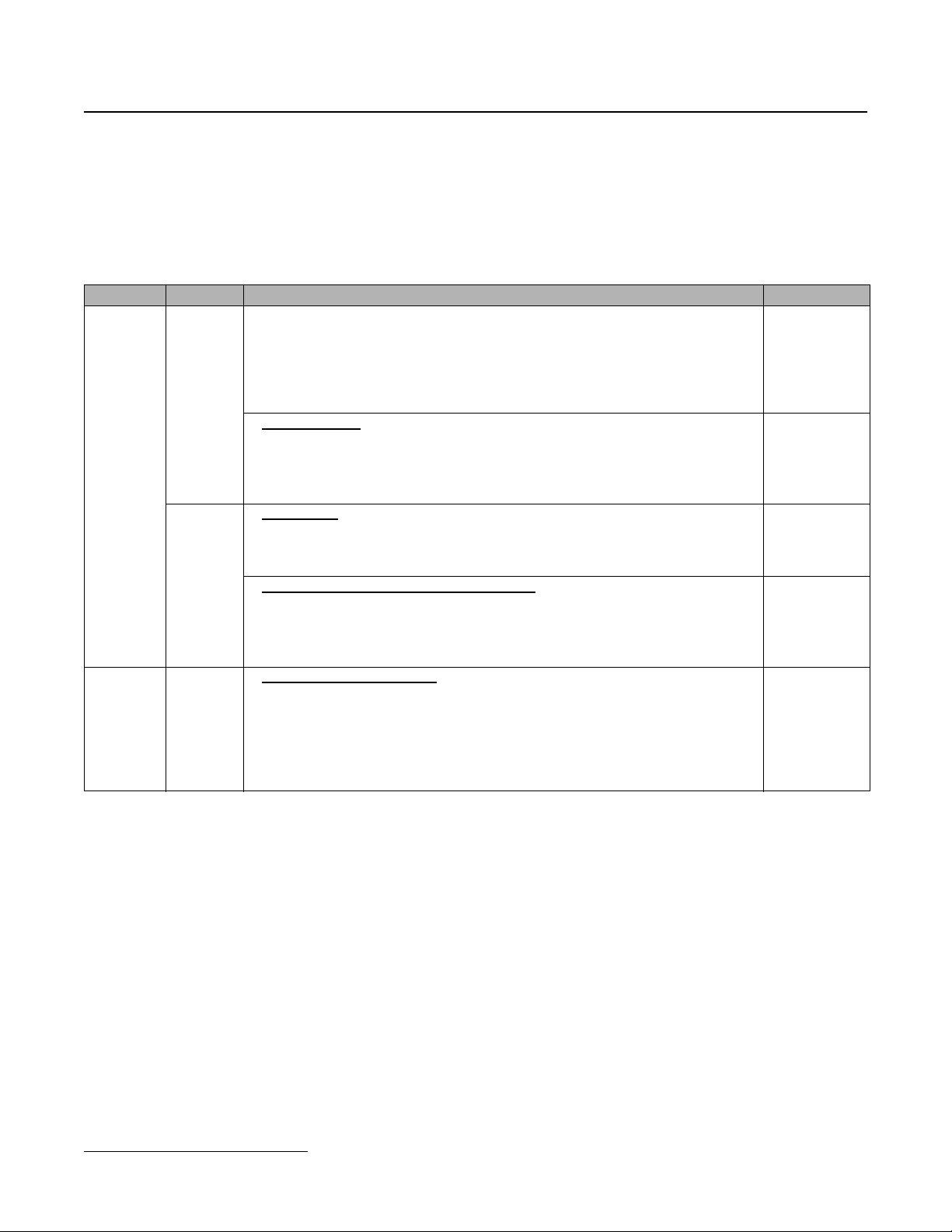
1.2 Drive Replacement Checklist
Item Checkpoints Checked?
Hardware
Basic
• Check if the new drive dimensions are bigger than the current drive. Can the mounting
holes be used?
– Verify that the existing dimensions reference in Section 1.5, “Dimensions,
installation space and substitution material” of this manual compares the sizes of the
current and new unit. If a mechanical substitution kit is necessary, it is referenced in
Section 1.5.
< Digital operator >
• Was a remote operator connected to the current unit?
– If so, do not attempt to connect the P3 Series 2 remote operator to the G+ Mini, as
they are incompatible.
– The digital operator for the G+ Mini can not be mounted remotely.
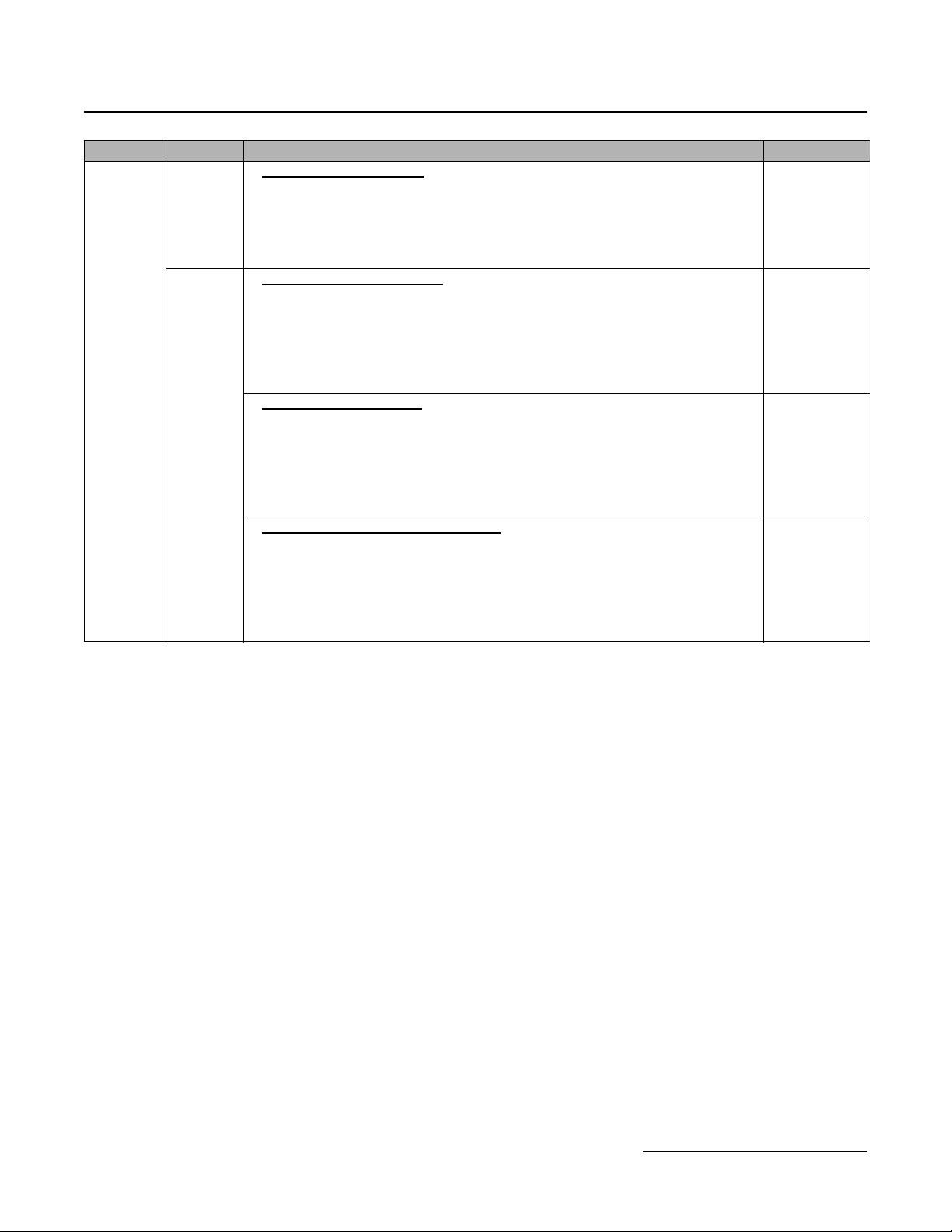
Main and
Control
Terminals
< Wire Length >
• In the replacement drive, the main and control circuit terminals may be mounted in
different positions. Check to ensure all cables are long enough to be connected to the
new unit.
< Main circuit wires and terminal specifications >
• Compare the occupied terminals of the current unit with the new drive’s terminals
(shape, size, etc.), and verify that the wires fit in the new unit’s terminals, using Section
1.4 “Terminals”, specifically “Control Terminal Sizes and Wire Sizes” of this
document.
Software Parameter
< Check the parameter settings >
• Read the parameter settings of the current unit and perform a parameter conversion to
the new parameters following Section 1.6 “Parameter Correspondence Table”,
specifically “P3 Series 2 and G+ Mini Differences in Parameter Settings” of this
document.
– If there is special software installed or parameters appear that are not mentioned in
this document, contact your Magnetek representative.