5
PREVENTIVE AINTENANCE
Periodic inspections are a necessary means to keep your level control in good working order. This control is a safety
device to protect the valuable equipment it serves. A systematic program of preventive maintenance must be implement-
ed when the control is placed into service. If the following is observed, your control will provide reliable protection of your
capital equipment for many years.
What to do
1. Keep control clean
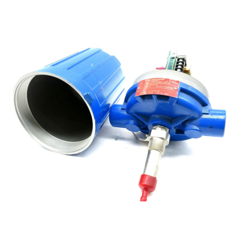
Be sure the switch housing cover is always in place on
the control. This cover is designed to keep dust and dirt
from interfering with the switch mechanism operation. In
addition, it protects against damaging moisture and acts
as a safety feature by keeping bare wires and terminals
from being exposed. Should the housing cover, or any
seals become damaged or misplaced, obtain a replace-
ment immediately.
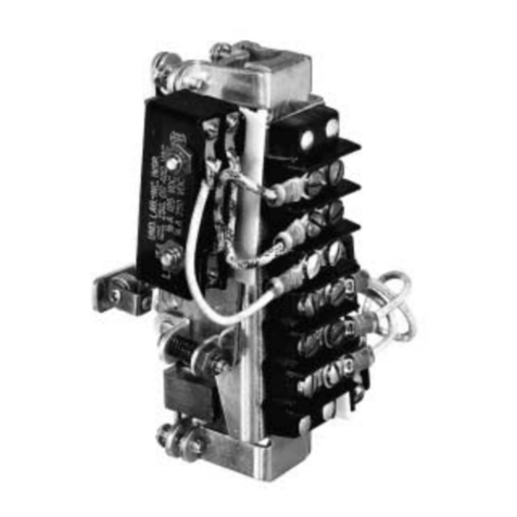
2. Inspect switch mechanisms, terminals, and connec-
tions monthly
a. Mercury switches may be visually inspected for short
circuit damage. Check for small cracks in the glass
tube containing the mercury. Such cracks can allow
entrance of air into the tube causing the mercury to
“oxidize”. This is noticeable as the mercury will
appear dirty or dull, and will not break into clean,
round pools. If these conditions exist, replace the
mercury switch immediately.
b. Dry contact switches should be inspected for exces-
sive wear on actuating lever or misalignment of
adjustment screw at point of contact between screw
and lever. Such wear can cause false switch actuating
levels. Adjust switch mechanism to compensate
(if possible) or replace switch.
c. DO NOT operate your control with defective or mal-
adjusted switch mechanism (refer to bulletin on switch
mechanisms furnished for service instructions).
d. Controls may sometimes be exposed to excessive
heat or moisture. Under such conditions, insulation on
electrical wiring may become brittle, eventually break-
ing or peeling away. The resulting bare wires can
cause short circuits.
Check wiring carefully, and replace it at the first sign
of brittle insulation.
What to do cont.
2. Inspect switch mechanisms, terminals, and connec-
tions monthly cont.
e. Vibration may sometimes cause terminal screws to
work loose. Check all terminal connections to be
certain that screws are tight.
f. On units with pneumatic switches, air (or gas) operat-
ing medium lines, subjected to vibration, may eventu-
ally crack or become loose at connections causing
leakage. Check lines and connections carefully and
repair or replace, if necessary.
NOTE: As a matter of good practice, spare switches should
be kept on hand at all times.
3. Inspect entire unit periodically
Isolate control from vessel. Raise and lower liquid level to
check for switch contact and reset.
What to avoid
1. NEVER leave switch housing cover off the control longer
than necessary to make routine inspection.
2. NEVER place a jumper wire across terminals to cut-out
the control. If a jumper is necessary for test purposes, be
certain it is removed before placing control into service.
3. NEVER attempt to make adjustments or replace switches
without reading instructions carefully. Certain adjustments
provided for in F50 controls should not be attempted in
the field. When in doubt, consult the factory or your local
representative.
4. NEVER use lubricants on pivots of switch mechanisms.
A sufficient amount of lubricant has been applied at the
factory to ensure a lifetime of service. Further lubrication
is unnecessary, and will only tend to attract dust and dirt
which can interfere with mechanism operation.
TROUBLESHOOTING cont.
If switch mechanism is operating satisfactorily, a test of the
complete control’s performance is the next likely step.
1. Reconnect power supply, and carefully actuate switch
mechanism manually, using a non-conductive tool, to
determine whether controlled equipment will operate.
2. If controlled equipment responds to manual actuation
test, trouble may be located in the flow sensing portion
of the control.
NOTE: Check first to be certain liquid is flowing through
pipeline. A valve may be closed, or pipeline may be plugged.
3. If magnet fails to pull in on increasing flow:
a. Disk may have too small a diameter.
b. Check for hang up or deposits in disk seat.
c. Check for malfunctioning by manually moving magnet
carriage.
4. If magnet fails to pull out on decreasing flow:
a. Disk may have too large a diameter.
b. Check for hang up or deposits in disk seat.
c. Check for malfunctioning by manually moving magnet
carriage.
If all components in the unit are in operating condition, the
trouble must be (and should be) located external to the unit.
Repeat inspection of external conditions previously
described.
CAUTION: With electrical power on, care should be
taken to avoid contact with switch leads and connections
at terminal block.
