MAGNOVENT FR3-43 User manual

MAGNOVENT
B U I L D I N G E F F I C I E N C Y
®
INSTALLATION GUIDE
FR
International edition 2019/07

An isola�on switch per fan is highly recommended.
WARNING. If unusual oscilla�ng movement is observed, immediately stop using the ceiling
fan and contact the na�onal distributer/retailer.
AEIM03AE - © MAGNOVENT, S.L. ® All rights reserved. July 2020.
The technical documenta�on is updated periodically. MAGNOVENT, S.L. reserves the right to modify all or part of
the contents of this manual without prior no�ce.
Available in:
43”/1092mm 50”/1270mm 60”/1524mm
LED Light Kit & Ceiling Extensin Kit are op�onal for all Aeratron models
!
2

!
Important information - Please read befo re attempting installation
3
1. Please read these instructions carefully, be mindful of all warnings and safety information
shown throughout this manual. Should you have any questions please call your local agent.
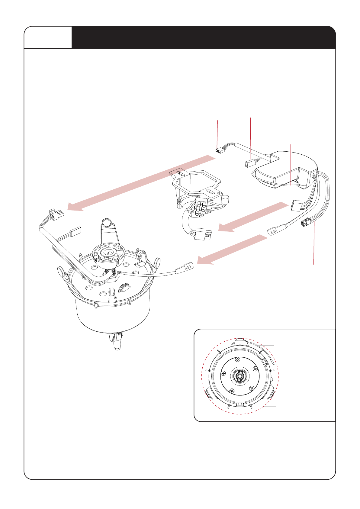
2. Please review the accompanying assembly diagrams before attempting installation.
3. This fan MUST be installed by a licensed & qualied electrician according to local authority
regulations and in accordance with current wiring rules of the country/state.
4. A copy of the purchasing receipt and proof of installation by a licensed and qualied electrician
according to local authority regulations is required for all warranty claims.
5. Where special access equipment is required to service the fan in accordance with local
authority regulations all associated costs are the responsibility of the owner.
6.
outs where the fan is found not to be defective and / or where access is not provided.
7. To enable future programming, maintenance, cleaning and troubleshooting an isolation switch
per fan is highly recommended. Without an isolation switch per fan, an electrician maybe
required to assist with programming, maintenance, cleaning and troubleshooting. All
associated costs are the responsibility of the owner.
8. A Maximum of 8 fans on each RCD / circuit is recommended. The fans are a Class 5 Device
with leakage to Earth.
9. Your warranty will be void if a solid state dimmer or any other brand of wall controller is used.
10. The means for mains power disconnection must be incorporated in the xed wiring in
accordance with national wiring rules.
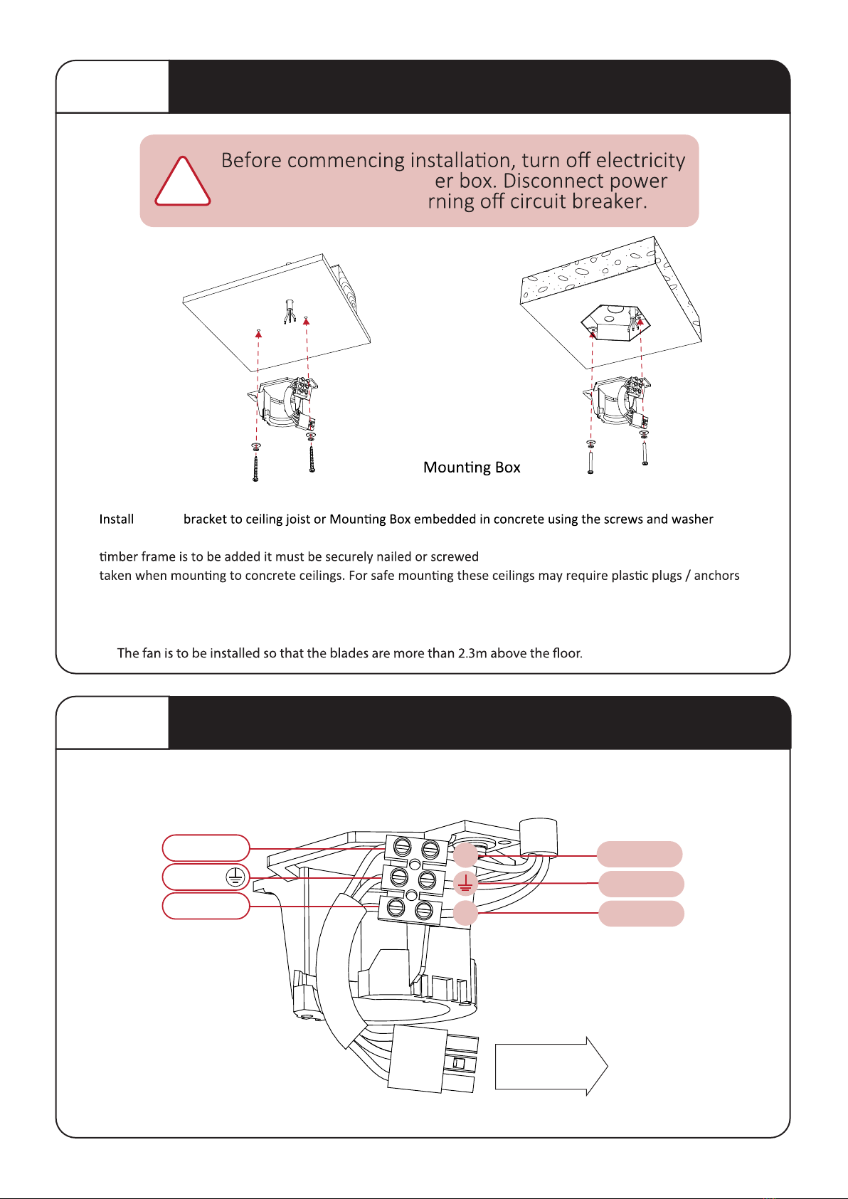
11. To avoid possible electric shock during installation, be sure electricity is turned o at the main
power box before commencing work. Disconnect power by removing fuse or turning o circuit
breaker before installing the fan. Ensure all spliced connections are adequately insulated.
12. Warning! Do not allow the rotating fan blades to come into contact with any object, this can
cause serious injury or death.
13. Damage caused by incorrect installation, Force-majeure, lightning, electrical surges & spikes,
exposure to water, pests or moisture is not covered under warra nty.
14. This appliance is not intended for use by persons (including children) with reduced physical,
their safety.
Australia, New Zealand: In accordance with AS/NZS60355-1 & ASNZS60355-2-80: “This
appliance is not intended for use by persons (including children) with reduced physical, sensory
safety. Children should be supervised to ensure that they do not play with the appliance.”
This fan must be installed by a licensed and quali ed

Contents
Content s ............................................................................................................................... ................... . 2
Unpacking your Fa n ............................................................................................................................... .. 3
Installing your Fan ............................................................................................................................... .... . 4
Option A - LED Light Ki t ........................................................................................................................ . 10
Option B - Ceiling Extensio n Kit ........................................................................................................... . 10
Option C - Raked Ceiling Kit .................................................................................................. ............... . 11
Technical Specicatio n ......................................................................................................................... . 12
Care and Cleanin g............................................................................................................................... .. . 13
Troubleshootin g ............................................................................................................................... ..... . 13
If the fan is nois y............................................................................................................................... .. 13
If the fan rotates but does not create much airo w........................................................................... . 13
General Informatio n............................................................................................................................... . 14
Normal Wear and Tear ....................................................................................................................... . 14
Ceiling Fan Warrant y ............................................................................................................................. . 14
Transfer of Warrant y .......................................................................................................................... . 15
The following is NOT covered by warranty . ....................................................................................... . 15
4
Aeratron ceiling fan warranty detail s ..................................................................................................... . 16
IMPO R TANT
assistance before leaving
Important Information ............................................................................................................. ....... ........... 1

5
Unpacking your fan
NOTE:
Unpack your fan and examine all parts, you should have the following:
CEILING SPACER x 2
HANGER BRACKET
MOTOR ASSEMBLY
CONTROL RECEIVER
MOTOR HOUSING
50” FAN BLADE
X3
43”FAN BLADE
X3 OR 60”FAN BLADE
X3
OR
REMOTE CONTROL
HUB UPPER
HUB LOWER
AAA BATTERIES x2
OR
TIMBER SCREWS X 2
PIVOT LOCK X1
HUB SCREWS X 10
MACHINE SCREWS X 2
WASHER X 2 WASHER X 2

STEP 1 Mounting Hanger Bracket to Ceiling
supply at the main pow
by removing fuse or tu
!
hanger
provided. Ensure ceiling joists are sound and of adequate size and strength to support a 35Kg (77lbs) load. If a
between two beams.Proper care must be
and stronger screws.
Ceiling Joist
OPTION A: OPTION B:
Embedded
STEP 2 Connecting M ains P ower to Terminal Block
TO RECEIVER
GREEN
BROWN L
FROM HOUSE
(mains Power)
BLUE N
6
WARNING: MOUNT ONLY TO AN OUTLET BOX MARKED ACCEPTABLE FOR FAN SUPPORT.
NEUT RAL
LIVE
GROUND
N
L

!
Inserting an otor into Hanger B racket
=
Ensure that lug on Hanger
Ball
STEP 4
is engaged in slot in suspension
Installing R eceiver into Hanger B racket
7
STEP 3
Learn Switch
Switch to “O” to pair receiver with the Remote control and
Switch to “X” to lock the pairing code with the Remote control
Slide Remote Control Receiver
into Hanger Bracket from the
opposite side of the Terminal block
XO

8
Connecting the Receiver
2PIN LED driver connection
3PIN
Aerial
1. Connect the
between DC Motor and Receiver.
2. Connect the 3PIN connector between
Mains Power and Reciever.
3PIN Mains Power
to Receiver
Aerial
3PIN Receiver to Motor
Fix Remote Control
Aerial to ceiling
within circle of Fan
Motor Housing
Housing perime ter
STEP 5
4PIN Receiver to Comms
(optional USE ONLY IF INSTRUCTED)
Earth Cable
3PIN
& Earth cable connector
(optional for LED Light)

9
Pairing is always required during
Note: “Learn” switch on receiver (STEP 4)
STEP 6
Controlling the Fan
2.
One remote control can control up to 8 fans (within a 7m (23”) radius).On ALL receivers verify that the
“Learn” switch is in the “O”
indicated by one ‘beep’. Within 60 seconds, press and hold the LEARN
Speed Up/Down - 1-6 Speed
Use forward mode (clockwise) for cooling.
warm air.
. (LIGHT SWITCH
!
1
4
53
2
Pairing per Remote Control.
O LIGHT DIMMING
‘LEARN ’ BUTTONLIGHT SWI TCH
| LIGHT ON/OFF
Pairing the Remote Control
NOTE:
1. On Receiver: Verify that the “Learn” switch is in the “O”
LEARN BUTTON &
4. Within 60 seconds
on the Remote Control
indicates successful pairing.
5. On Receiver: switch the “Learn” switch to “X” (this will
lock the pairing code with the remote)
6. Finish STEP 7, 8 & 9 and press ON/SPEED
7. To re-pair, repeat steps 3 to 5
NOTE:
Pairing a Single Fan per remote control: LEARN MODE
The Remote Control and Fan Receiver will memorise the pairing
LIGHT SWITCH

10
STEP 7 Attaching the Fan Motor Housing
Align the 3 tabs with the 3 holes on the
Housing and move upwards. Push tabs
inwards slightly before sliding upwards
STEP 8 Assembling the Fan Blades
A B
Place the Hub Upper onto a clean working area.
with the 2 holes in the Hub Upper.
screws for each Blade.
be used.
CLICK!
!
avoid damaging the fan/surface

C
Lock Screw
11
Attaching the Fan Blades
44
STEP Assembling the Fan Blades cont.
C D
Fasten the the Hub Lower from the top side
using the 3 Hub Screws.
Lower) into the recess. With care, turn the fan
over.
No liability is accepted if the Silicone ring is
!
the clearance ‘X’ between
the ceiling and motor
housing is equal all way
round.
Align
Connector and slide fan
D
Hold/push up Fan Blades
and insert Pivot Lock,
sideways. Push Pivot Lock
Tighten Lock Screw
securely using screw driver.
Do not use power tools.
x
A
Pivot Connector
Silicone Ring
B
Pivot Lock
Silicone Ring
Light Hub Lower
(OPTIONAL)
STEP 9
8

12
44
OPTION A LED Light Kit
OPTION B Ceiling Extension Kit
Line up the 2pins on the LED light with the 2Holes in the
Safety clip is engaged.
Re-check the correct assembly by gently pulling on the
LED LIGHT
”A“
150mm (6”)
“B”
26.6mm ROD
Suitable for Raked Ceiling up to 15
“B” Extension Rod Length
115mm Rod (4 17/32”)
600mm Rod (23 5/8”)
900mm Rod (35 7/16”)
Accessories Required
Included
Not Included
Not Included
“A” Ceiling to Fan blade
420mm (16 17/32”)
910mm (35 53/64”)
1210mm (47 41/64”)

13
OPTION C Raked Ceiling Kit
CEILING JOIST
“B”
“C”
“a”
“B” Extension Rod Length
115mm Rod (4 17/32”)
600mm Rod (23 5/8”)
900mm Rod (35 7/16”)
Accessories Required
Included
Not Included
Not Included
“C” Clearance
200mm min.
200mm min.
“a” Angle
15° - 17°
17° - 33°
33° - 40°

14
Technical Specications
180mm (7”) 275mm (10 53/64”)
43” 1092mm / 50” 1260mm / 60” 1524mm
172mm (6 49/64”)
Dimensions for Model:
FR3 43”, FR3 50”, FR3 60”
Fan Weight:
FR3 43” = . kg (1 . lbs)
FR3 50” = . kg (1 . lbs)
FR3 60” = . kg (1 . lbs)
White/Silver/Black
Dark/Light wood-grain
Remote Control:
Hand held, RF
Wall switch control
MODEL SPEED 1 SPEED 2 SPEED 3 SPEED 4 SPEED 5 SPEED 6
FR3-43 70rpm/4.5W
57rpm/4.4W
57rpm/4.5W
99rpm/6W
93rpm/9.3W
80rpm/6.7W
126rpm/8.4W
122rpm/11W
101rpm/9.6W
151rpm/11.3W
142rpm/15W
126rpm/14.5W
181rpm/15W
160rpm/20.4W
150rpm/22.5W
207rpm/20W
180rpm/26.2W
166rpm/28.5W
FR3-50
FR3-60
MODEL SPEED 1 SPEED 2 SPEED 3 SPEED 4 SPEED 5 SPEED 6
FR3-43 70rpm/3.2W
57rpm/3.2W
56rpm/3.1W
96rpm/4.4W
92rpm/5.8W
82rpm/5.2W
125rpm/6.4W
122rpm/9.8W
102rpm/8.3W
156rpm/9.6W
141rpm/14W
128rpm/14W
181rpm/13.4W
162rpm/19.2W
151rpm/20.5W
205rpm/19.8W
181rpm/25.9W
168rpm/28.5W
FR3-50
FR3-60

15
Ca re and Cleaning
!
Except for items 1 to 3 below, the following require access to
areas of the fan which carry lethal voltage and must be carried
1.
6.
7.
8.
9.
10.
11.
Regular cleaning of the Aeratron Ceiling fan blades and fan motor housingis the onlymaintenance needed.
Due to the self-balancing design, a large build up of dust on blades may create an imbalance in extreme cases
only, causing the blades to wobble during use. This is likely to be more apparent on fans with an extension rod.
Regular cleaning of the blade is recommended to prevent dust from building up.
Troubleshooting
cleaning your fan, only use a brush or lint free cloth to scratching the
use water when cleaning your ceiling fan. It could damage the motor or blades and/or
create the possibility of electric shock.
the fan may wobble.
humidity ranges.
If the fan is noisy
Check to make sure that Suspension Ball is located in the slot correctly, and the one screw
Note:

16
General Information
NOT a fault.
1. All electrical motors, including fan motors generate some noise, and may feel hot to the touch. This is
Normal Wear and Tear.
Threaded components working slightly loose or parts even slightly damaged or bent during vigorous cleaning
or bumping can cause wobble and noise. This is notcovered under warranty, but care during maintenance and
cleaning should prevent this from occurring.
Warranty
You must have the original purchase receipt or bill of sale to make a warranty claim. No claim will be
Ceiling Fan Warranty Period.
product claims must be lodged through your local retailer/distributor. Labour and product delivery costs are
borne by Aeratron Pty Ltd or the retailer during this 3 year period. The cost of obtaining or using special access
provide such equipment and have it safely installed and operated.
Remote Control Warranty Period.
described above for fans.
Balance of Warranty on Repaired or Replaced Products.
Any replaced or repaired product is covered onlyby the balance of the warranty remaining on the original
Aeratron fan is mounted securely on a metal Hanger Bracket with rubber cushioning and a ball joint to
are exactly the same - some may move more than others. Note: Excessive wobble can be caused by
Fan Motor Assembly in the Hanger Bracket (see step (D) page ).
dry ones.
to the ceiling, where it cannot be felt by the occupants of a room, especially in areas with high
ceilings. The fan assists to distribute warm air more evenly in the room allowing to set the
thermostat several degrees lower.

Transfer of Warranty.
If the dwelling where the fan is installed changes hands,the balance of the warranty passes to the new owner,
providing the original bill of sale for the product is retained by the new owner.
Warranty does not cover damage to the fan if it is moved from one dwelling to another during the warranty
period. The warranty is voided in total if the product is sold as second hand goods.
The following is NOT covered by warranty.
17
Warranty Cont.
IMPO R TANT
assistance before leaving
Making a Claim
Electrician to make a warranty claim. No claim will be accepted without these documents being provided.
Please contact the local agent via the warranty Hotline, web or email.
Please note carefully
2. Ceiling fans not installed by a licensed electrician.
3. Repair of a ceiling fan used incorrectly, accidentally damaged, ed in any way or not serviced in
4. Travelling costs incurred by Aeratron Pty Ltd personnel or service agents and/or the cost of
5. Subject to any statutory provisions to the contrary, claims for damage to furniture, carpet, walls,
ceiling fan.
6. Signals sent through the mains power supply by the electricity supplier for peak hot water, and
humming in the ceiling fan. It is not the fault of the ceiling fan.
8. When humidity is high and temperature drops moisture condenses on metal surfaces including
ceiling fans. The layer of moisture can be almost microscopic but it will
corrosion if the product is not properly and regularly cleaned.
9. Travelling costs incurred by Aeratron personnel or service agents exceeding 50kms between the
nearest agents’ service depot and the customer. These costs must be met by the purchaser.

18
Warranty Details
Fan Details
Aeratron ceiling fan warranty details
Please File with your Purchase Receipt
Customer Details
Name; ______________________________________________
Address: ____________________________________________
Post Code: ___________________________________________
Phone Number: _______________________________________
Electricians Details
Model: ______________________________________________
Colour: ______________________________________________
Date of Purchase: ______________________________________
WARRANTY PHONE NUMBER
AUSTRALIA 1300 116 305 (9am to 5pm EAST)
model and colour of the fan. The installing electrician’s details may also be required.
Name of Electrician: ____________________________________
Licence Number: _______________________________________
IMPO R TANT
assistance before leaving
or please go to www.aeratron.com/contact

HEADQUARTERS SOCIAL MEDIA
P.E. Táctica | c/ Maña, 32 46980 Paterna
(Valencia) Spain
www.magnovent.eu
@MagnoventClimateSolutions
@Magnovent
Magnovent
19

“As much as we sould like to take full credit for the desich
of your Aeratron fan, we need to admit, we weren't the first
to think of it.
The profile of the Aeratron blade and the winglet at its end
reduce turbulence, providing more airflow with less energy,
siletly. Great idea.”
This manual suits for next models
2
Table of contents
Other MAGNOVENT Fan manuals