Page 4
4. OPERATION
4.01 To operate the inverter, switch the
output circuit breaker switch to “ON”. Also
switch “ON” the inverter on/off switch and
the remote on/off switch (if used).
5. TROUBLESHOOTING
5.01 Sensata offers free phone consulta-
tion concerning installation or troubleshoot-
ing. Call the Customer Service Department
at 800-553-6418 or 651-653-7000;
fax: 651-653-7600.
NOTE: Since the inverter has a quasi-sine
waveform, a TRUE RMS volt meter is
required for an accuarte reading. Other volt
meters that use averaging circuitry will give
incorrect readings.
5.02 If the inverter fails to operate, use
the following trouble-shooting procedure.
5.02.1 Connect a 100 watt light bulb to
each 120 VAC phase and disconnect all
other output wiring.
5.02.2 Make sure the inverter is “ON”
and the output circuit breaker is also “ON”.
5.03.3 Observe the fault indicating lights
on the front of the inverter.
a) If the low input voltage light is lit, turn
inverter “Off” for 5 seconds, then turn “On”
again. If the light again turns on, check
wiring, DC source voltage, battery condition
and line fuse.
b) If the overload light is lit, check output
wiring for short circuit. Otherwise, the load is
too large for the power rating of the in-
verter.
c) If the high temperature light is lit, the
inverter must be left cool to 40o C (104o F).
Check to see that the inverter is not in a
closed compartment and that the fans are
not blocked.
5.03.4 If the above steps are completed
and the inverter still will not operate satisfac-
torily call Sensata for a return authorization
number.
3.06.3 The switch should be mounted at
a convenient location in a listed outlet box
with approved strain relief.
3.06.4 The remote switch should be
connected to the violet wire marked “Re-
mote Switch Hookup” in the wiring compart-
ment. Positive (+)12 battery voltage must
be connected to the other side of the
switch. Cable clamp strain relief should be
used to secure the field wires.
3.06.5 Units with a model designation
ending in "R6" have the remote On/Off
switch circuit modified to accept +24 VDC
instead of +12 VDC. The remote switch
must be connected to the violet wire
marked "Remote Switch Hookup".
3.07 220Y/120 VAC Output
3.07.1
CAUTION:
Do not connect
another source of AC power directly to the
output of the inverter. This will result in
damage to the inverter that is not covered
under warranty!
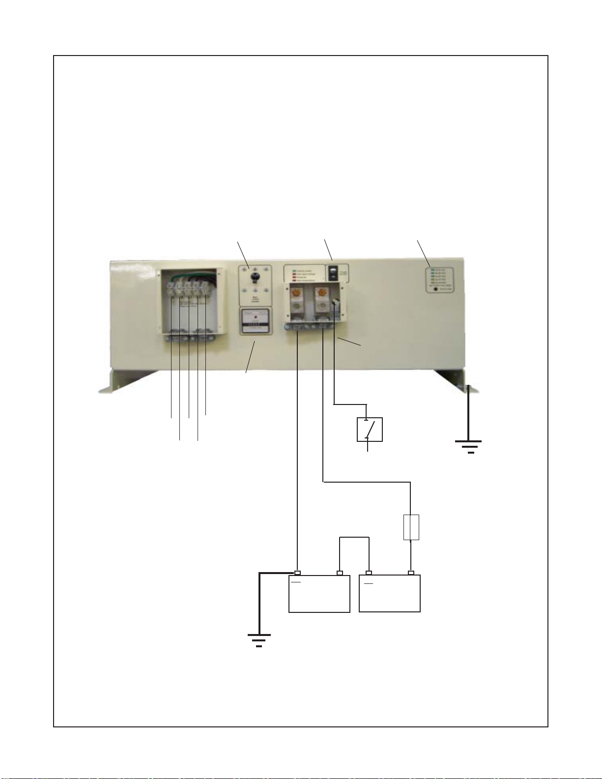
3.07.2 The A.C. output is presented at
the A.C. wiring compartment. The 3 phase
outputs are labeled “L1”, “L2”, “L3”. There
is also an A.C. neutral labeled “N” and a
chassis ground labeled “G”.
3.07.3 To obtain 220 VAC, 3 phase
output, a connection must be made to
L1,L2, and L3.
3.07.4 To obtain 220 VAC, single phase
output, a connection should be made to
any two of the hot leads, as L1 and L2, or
L1 and L3, or L2 and L3.
3.07.5 To obtain 120 VAC, single phase
output a connection. should be made to
any one hot lead and to AC neutral “N”; as
L1 and N, or L2 and N, or L3 and N.
3.07.6 Remote AC outlets should be
mounted at a convenient location in a listed
outlet box with approved strain relief, if
used.