Magnum MLT5060 User manual

LIGHT TOWER
MLT5060 • MLT5080
OPERATING/PARTSMANUAL

2
Thismanualprovidesinformationandprocedurestosafelyoperateandmaintaintheengineandgenerator. Foryour
ownsafetyand protection from physical injury, carefully read, understand,andobservethesafetyinstructions
described in this manual. The information contained in this manual was based on machines in production at the
time of publication. Magnum Products LLC reserves the right to change any portion of this information without
notice.
DO NOT MODIFY or use this equipment for any application other than which it was designed for.
MagnumProductsLLCrecommendsthat atrainedand licensedprofessionalperform allelectricalwiring andtesting
functions. Any wiring should be in compliance with the United States National Electric Code (NEC), state and local
codesand OccupationalSafety andHealthAssociation(OSHA) guidelines.
Keep a copy of this manual with the unit at all times. Additional copies are available from Magnum Products LLC.
An engine operators manual was also supplied with the unit at the time of shipment from the factory. The manual
providesdetailedoperation and maintenance procedures for the engine. Additional copies of the engineoperators
manualareavailable from theenginemanufacturer.
MAGNUM PRODUCTS LLC
215 Power Drive • Berlin, WI 54923
U.S.A.
Phone: 920-361-4442
FAX: 920-361-4416
Toll Free: 1-800-926-9768
www.m-p-llc.com
CALIFORNIA PROPOSITION 65 WARNING:
Diesel engine exhaust and some of its constituents are known to the state
of California to cause cancer, birth defects and other reproductive harm.
WARNING
Engine Make:
Engine Serial Number:
Engine Model Number:
Generator Make:
Generator Model Number:
Generator Serial Number:
Unit Model Number:
Unit Serial Number:
When calling for Parts or Technical Service information,
please have your unit model number and serial number ready.

3
TABLE OF CONTENTS
Page
INTRODUCTION ..............................................................................................................................2
TABLEOFCONTENTS ...................................................................................................................3
SAFETYNOTES.............................................................................................................................4
OPERATINGSAFETY.....................................................................................................................4
ENGINESAFETY ...........................................................................................................................5
SERVICESAFETY .........................................................................................................................5
TOWINGSAFETY ..........................................................................................................................6
UNITSERIALNUMBERLOCATIONS ..............................................................................................6
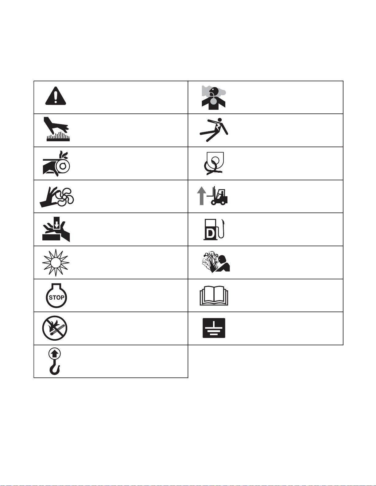
SAFETYSYMBOL SUMMARY.......................................................................................................7
SPECIFICATIONS ....................................................................................................................8 - 11
LIGHTTOWERSET UP ................................................................................................................12
RAISINGTHE TOWER.......................................................................................................... 12 - 14
MAINCONTROLPANELCOMPONENTS .....................................................................................15
ENGINESTARTINGANDOPERATION .........................................................................................16
AUTOMATICSHUTDOWN ............................................................................................................16
LIGHTOPERATION.......................................................................................................................17
AUXILIARYOUTLETS ...................................................................................................................17
VOLTAGEREGULATION(OPTIONAL) ..........................................................................................17
DERATINGFORALTITUDE ...........................................................................................................18
SHUTTINGDOWN ........................................................................................................................18
LOWERINGTHE TOWER......................................................................................................18 - 19
TOWINGTHETRAILER ................................................................................................................19
LIFTINGTHETRAILER..................................................................................................................20
DAILYINSPECTION......................................................................................................................20
TRAILERWHEELBEARINGS ......................................................................................................21
ENGINEMAINTENANCE ..............................................................................................................22
OPTIONALLOWERRADIATORHOSEHEATERUSEANDMAINTENANCE................................23
TROUBLESHOOTINGTHELIGHTS ..............................................................................................23
MASTLIGHT CONNECTIONS .......................................................................................................24
UNITDECALS........................................................................................................................24 - 28
GENERATORASSEMBLY6 kW...................................................................................................29
GENERATORASSEMBLY8 kW...................................................................................................30
GENERATORASSEMBLY8 kW WITH VOLTAGE REGULATION .................................................31
MANUALWINCH MASTASSEMBLY.....................................................................................32 - 33
ELECTRICWINCHMASTASSEMBLY ..................................................................................34 - 35
ENCLOSUREASSEMBLY .....................................................................................................36 - 37
FRAMEASSEMBLY ..............................................................................................................38 - 40
MASTJUNCTIONBOXASSEMBLY,QUICKDISCONNECTLIGHTS .............................................41
MASTJUNCTIONBOXASSEMBLY,HARDWIREDLIGHTS .........................................................42
MASTJUNCTIONBOXASSEMBLY,6LIGHTQUICKDISCONNECT.............................................43
MITSUBISHIENGINE.............................................................................................................44 - 45
KUBOTAENGINE ..................................................................................................................46 - 47
CONTROLBOXAND PANELASSEMBLY..............................................................................48 - 49
LIGHTASSEMBLY.................................................................................................................50 - 51
METALHALIDEBALLASTBOXASSEMBLY ................................................................................52
HIGHPRESSURESODIUMBALLASTBOXASSEMBLY..............................................................53
WIRINGDIAGRAMS ..............................................................................................................51 - 59

4
This is the safety alert symbol. It is used to alert you to potential personal injury hazards.
Obey all safety messages that follow this symbol to avoid possible injury or death.
ThismanualcontainsDANGERS,WARNINGS,CAUTIONS,NOTICESandNOTESwhichmustbe
followedtopreventthepossibilityofimproperservice,damage totheequipment,personalinjuryordeath.
Thefollowingformatting options willapplywhencallingthe readersattentiontotheDANGERS, WARN-
INGS,CAUTIONS,NOTICESandNOTES.
SAFETY NOTES
NOTICE
Indicatesa hazardoussituationwhich,ifnotavoided,
mayresultin property orequipmentdamage.
Note: Notescontainadditional information importanttoaprocedureand will befoundwithintheregular
text body of this manual.
DANGER
INDICATESAHAZARDOUSSITUATIONWHICH,IFNOTAVOIDED,
WILLRESULTINDEATHORSERIOUSINJURY.
WARNING
Indicates a hazardous situation which, if not avoided,
could result in death or serious injury.
CAUTION
Indicates a hazardous situation which, if not avoided, may result in minor or moderate injury.
OPERATING SAFETY
Before using the light tower be sure you read and understand all of the instructions! This equipment was
designedforspecificapplications;DONOTmodifyorusethisequipmentforanyapplicationotherthanwhich
itwasdesignedfor. Equipmentoperatedimproperlyorbyuntrainedpersonnelcanbedangerous! Readthe
operatinginstructionsandfamiliarizeyourselfwiththelocationandproperuseofallinstrumentsandcontrols.
Inexperiencedoperatorsshouldreceiveinstructionfromsomeone familiarwiththeequipmentbeforebeing
allowed to operate or set up the light tower. The following points should be practiced at all times:
•Theareaimmediately surrounding thelighttowershouldbedry, clean, andfreeofdebris.
•Positionandoperatethe light tower on a firm, level surface.
• NEVER startaunit in need of repair.
•Lower tower when not in use, or if high winds or electrical storms are expected in the area.
•Makecertainlighttoweriswellgroundedandsecurelyfastenedto a good earthen ground.
•Thetowerextendsupto30ft.(9m). Makesureareaabovetrailerisopenandclearof overhead wires
andobstructions.
•Bulbs become extremely hot in use! Allow bulb and light fixture to cool 10-15 minutes before han-
dling.
•Keepareabehindtrailerclearofpeoplewhileraisingandloweringmast!
• NEVER raise,lowerorturnmastwhile unit is operating!
•Trailermustbeleveledandoutriggersextendedbeforeraisingtower. Outriggersmustremainex-
tendedwhile tower is up.
•Iffor any reason anypart of mast hangsup or winch cabledevelops slack while raisingor lowering
tower,STOPimmediately! Contactanauthorizedservicerepresentative.
• NEVER removesafety pin or pull mastlocking pin while tower isup!
• NEVER use tower if insulation on electrical cord is cut or worn through.
• NEVER operatelights without protective lens cover in place or with alens cover that is cracked or
damaged!

5
Internalcombustionenginespresentspecialhazardsduringoperationandfueling! Failuretofollowthe
safety guidelines described below could result in severe injury or death. Also read and follow all safety
warnings described in the Engine Operator's Manual. A copy of this manual was supplied with unit when
it was shipped from the factory.
• DO NOT run engine indoors or in an area with poor ventilation unless exhaust hoses are used. Diesel
engine exhaust contains carbon monoxide, a deadly, odorless and colorless gas which, if inhaled,
can cause nausea, fainting or death. Make sure engine exhaust cannot seep into closed rooms or
ventilationequipment.
• DO NOT fill fuel tank near an open flame, while smoking, or while engine is running. DO NOT fill tank
inanenclosedareawithpoorventilation.
• DO NOT operate with the fuel tank cap loose or missing.
• DO NOT touch or lean against hot exhaust pipes or engine cylinders.
• DO NOT clean air filter with gasoline or other types of low flash point solvents.
• DONOTremove engine coolantcapwhileengineis hot.
•Keep area around exhaust pipes and air ducts free of debris to reduce the chance of an accidental
fire.
•Prolonged exposure to sound levels in excess of 85 DBA can cause permanent hearing loss. Wear
hearing protection when working around a running engine. DO NOT operate the unit without a
functionalexhaustsystem.
•Batteries contain sulfuric acid which can cause severe injury or death. Sulfuric acid can cause eye
damage,burnflesh or eat holes in clothing. Protective eyewearandclothing are necessary when
working on or around the battery. Always disconnect the NEGATIVE (-) battery cable from the
correspondingterminalbeforeperforminganyserviceontheengineorothercomponents.
• Shuttheenginedownif any of the following conditions exist during operation:
1. Noticeablechangeinenginespeed.
2. Loss of electrical output.
3. Equipmentconnectedtothe generator overheats.
4. Sparkingoccurs.
5. Enginemisfiresorthere is excessive engine/generator vibration.
6. Operatingonacombustiblesurface.
7. Protectivecoversarelooseormissing.
8. Iftheambientairtemperatureisabove110°F.
ENGINE SAFETY
This unit uses high voltage circuits capable of causing serious injury or death. Only a qualified electrician
shouldtroubleshoot orrepairelectricalproblemsoccurringinthis equipment.
•Before servicing light tower, make sure the engine start switch is turned to OFF, circuit breakers are
open(off)andthenegativeterminalonthebatteryisdisconnected.NEVERperformevenroutine
service (oil/filter changes, cleaning, etc.) unless all electrical components are shut down.
• NEVER allow water to accumulate around the base of the light tower. If water is present, DO NOT
service!
• NEVER service electrical components if clothing or skin is wet. If the unit is stored outside, check
theengineandgeneratorfor any moisture and drytheunitbeforeuse.
• NEVER washtheunitwith a powerwasherorhighpressure hose.
•Openmaincircuitbreakerbeforedisconnectingbatterycables.
•Keephands,feet,and looseclothingawayfrommovingpartsongeneratorandengine.
•Make sure slings, chains, hooks, ramps, jacks, and other types of lifting devices are attached
securelyandhaveenough weight-bearing capacity to lift or hold the equipmentsafely. Always
remainawareofthepositionofotherpeoplearoundyouwhenliftingtheequipment.
SERVICE SAFETY

6
MANUFACTURED BY/FABRIQUE PAR:
GVWR/PNBV:
DATE OF MFG:
COLD INFL. PRESS./PRESS.
GAWR/PNBE TIRE/PNEU RIM/JANTE KPA(PSI/LPC)
THIS VIEHICLE CONFORS TO ALL APPLICABLE STANDARDS PRESCRIBED UNDER THE CANADIAN MOTOR VIEHICLE SAFETY REGULATIONS
IN ECCEFT ON THE DATE OF MANUFACTURE. / CE VEHICULE EST CONFORME A TOUTES LES NORMES QUI LUI SONT APPLICABLES EN
VERTU DU REGLEMENT SUR LA VEHICULES DES AUTOMOBILES DU CANADA EN VIGUEUR A LA DATE SA FABRICATION.
THIS VIEHICLE CONFORMS TO ALL APPLICABLE U.S. FEDERAL MOTOR VEHICLE SAFETY STANDARDS (FMVSS) IN EFFECT ON THE DATE OF
MANUFACTURE SHOWN ABOVE.
V.I.N./N.I.V.: TYPE/TYPE DE VEHICULE:
Serial Number
kg lbs
rpm hz amb. temp.
V
A
Model
RATING: CONT. STAND BY
3 Phase 1 Phase
KVA
LR 114630-1
FOR ELECTRICAL
EQUIPMENT ONLY.
POUR MATERIAL
ELECTRIQUE SEULEMENT.
MADE IN USA
PRODUCTS LLC
215 Power Drive
Berlin, WI 54923
1-800-926-9768
TM
Mfg. Code
V
A
KW
®
Unit ID Tag
V.I.N. Tag
Towinga trailer requires care! Both thetrailer and vehicle must bein good condition and securelyfas-
tened to each other to reduce the possibility of an accident. Also, some states require that large trailers
beregistered and licensed. Contact your localDepartment of Transportation office tocheck on license
requirementsforyourparticularunit.
•Check that the hitch and coupling on the towing vehicle are rated equal to, or greater than, the trailer's
"grossvehicleweightrating"(GVWR).
• Checktiresontrailerfortreadwear,inflation,andcondition.
•Inspectthehitch andcouplingforwearor damage. DO NOT towtrailerusing defectiveparts!
•Make sure the trailer hitch and the coupling are compatible. Make sure the coupling is securely
fastenedtothevehicle.
•Connect safety chains in a crossing pattern under the tongue and attach the breakaway cable TO
THE REAR BUMPER OF THE TOWING VEHICLE. Do not attach the cable to the trailer hitch.
•Makesuredirectionalandbrakelightson the trailer are connected and working properly.
•Check that all lug nuts holding wheels on are tight and that none are missing.
•Maximumrecommendedspeedforhighwaytowingis45m.p.h. Recommendedoff-roadtowingspeed
is not to exceed 10 m.p.h. or less depending on terrain.
Whentowing,maintainextra space between vehicles and avoid soft shoulders, curbs andsuddenlane
changes. Ifyou have not pulleda trailer before, practiceturning, stopping, and backingup in an area
awayfromheavy traffic.
A film of grease on the coupler will extend coupler life and eliminate squeaking. Wipe the coupler clean
and apply fresh grease each time the trailer is towed.
TOWINGSAFETY
REPORTING TRAILER SAFETY DEFECTS
If you believe your trailer has a defect which could cause a crash or could cause injury or death, you should immedi-
atelyinformtheNational HighwayTrafficSafetyAdministration(NHTSA)inaddition to notifying Magnum Products
LLC. If NHTSA receives similar complaints, it may open an investigation; and if it finds that a safety defect exists in
agroupofvehicles,itmayorderarecallandremedycampaign. However, NHTSAcannot become involved in
individualproblembetweenyou,yourdealer, or Magnum ProductsLLC.
To contactNHTSA,youmay either call theAutoSafety Hotline toll-free at 1-888-327-4236 orbyfax at: (202)-366-
7882. Additionalcontactinformation can be found at: www.nhtsa.dot.gov.
UNIT SERIAL NUMBER LOCATIONS
Refer to the locations illustrated to find the unit ID
tag, and trailer ID tag on your unit. Important
information,such as the unit serial number, model
numberandVehicleIdentificationNumber(V.I.N.)for
your trailer are found on these tags. Record the
information from these tags, so it is available if the
tags are lost or damaged. When ordering parts or
requestingtechnicalserviceinformation,youmay be
asked to specify this information.

SAFETY SYMBOL SUMMARY
Thisequipmenthasbeensuppliedwithnumeroussafetyandoperatingdecals. Thesedecalsprovideimportant
operatinginstructionsandwarn of dangers andhazards. Replaceanymissingorhard-to-readdecals and use care
when washing or cleaning the unit. Decal placement and part numbers can be found in the beginning of the parts
section of this manual. Below is a summary of the intended meanings for the symbols used on the decals.
7
UV
Hot surface(s) nearby.
Fire/explosion hazard; Keep
open flames away from unit.
Read and understand the
supplied operator’s manual
before operating unit.
Ultraviolet radiation hazard;
Operate only with lens intact.
Use clean diesel fuel only.
Unit electrical ground.
Anchor/tie down point.
Lift here only.
Asphyxiation hazard; Operate
in well ventilated area.
Dangerous voltage may be
present.
Crush hazard; Keep body parts
clear of this area.
Burn/scald hazard;
pressurized steam.
Fan hazard; Keep body parts
clear of this area. Forklift here only.
Belt/entanglement hazard; Keep
body parts clear of this area.
Safety alert symbol; Used to
alert you to potential personal
injury hazards.
Stop engine before fueling.

8
SPECIFICATIONS
Readthismanual carefully before attempting to use thislighttower. The potentialforproperty damage, personal
injury or death exists if this equipment is misused or installed incorrectly. Read all of the manuals included with this
unit. Each manual details specific information regarding items such as set up, use and service requirements.
Specifications are subject to change without notice.
MAGNUMMODEL MLT 5060
Engine
Make/Brand ........................................................ MITSUBISHI .............................KUBOTA
Model.................................................................. L3E-W461ML (start S#081485).......D905-E3BG
Type .................................................................... Diesel, liquid cooled, 4-stroke....Diesel, liquid cooled, 4-stroke
Horsepower-prime hp (kW) ............................... 10.5(7.8) ...................................10.5(7.8)
Horsepower - standby hp (kW) ........................... 12.2(9.1) ...................................11.9(8.9)
OperatingSpeed rpm ......................................... 1800 ..........................................1800
Displacementin3(L) ........................................... 57.97 (0.95) ...............................54.92(.90)
Cylinders - qty .................................................... 3 ................................................3
Fuel Consumption - 100% prime gph (Lph) ....... 0.52(1.97) .................................0.50(1.89)
BatteryType - Group Number ............................. 24 ..............................................24
BatteryVoltage(Quantity per Unit) ..................... 12V (1).......................................12V(1)
BatteryRating..................................................... 440CCA ....................................440CCA
Generator
Make/Brand ........................................................ MarathonElectric ......................Marathon Electric
Model.................................................................. 201CSA5411..............................201CSA5411
Type, Insulation................................................... Brushless, F ..............................Brushless, F
Generator Set (Engine/Generator)
OutputkW (kVA)................................................. 6.0(6.0) .....................................6.0(6.0)
Output Voltage V................................................ 120/240, single phase................120/240,singlephase
OutputAmperes 120V (240V) A .......................... 50(25) .......................................50(25)
FrequencyHz ..................................................... 60 ..............................................60
PowerFactor ...................................................... 1(1Ø) ........................................1(1Ø)
Weights
DryWeightlbs (kg)............................................. 1771(803) .................................1816(824)
OperatingWeightlbs (kg) ................................... 1920(871) .................................1965(891)
Capacities
Fuel Tank Volume gal (L) ................................... 30(114)......................................30(114)
Usable Fuel Volume gal (L) ................................ 30(114)......................................30(114)
Coolant(incl.engine) qt (L)................................. 4.5 (4.3).....................................4.8(4.5)
Oil (incl. filter) qt (L)............................................ 3.8 (3.6) .....................................5.4 (5.1)
MaximumRunTimehrs...................................... 58 ..............................................60
ACDistribution
Circuit Breaker Size............................................ 30 ..............................................30
VoltageRegulation .............................................. Capacitor+/-6%.........................Capacitor+/-6%
VoltagesAvailable1Ø ......................................... 120,240.....................................120,240

9
SPECIFICATIONS
Readthismanual carefully before attempting to use thislighttower. The potentialforproperty damage, personal
injury or death exists if this equipment is misused or installed incorrectly. Read all of the manuals included with this
unit. Each manual details specific information regarding items such as set up, use and service requirements.
Specifications are subject to change without notice.
MAGNUMMODEL MLT 5060
Lighting
LightingType....................................................... MetalHalide
BallastType........................................................ Coil & Core
Lumens............................................................... 440,000
Coverageacres(m2)........................................... 5-7(20,234 - 28,328)
Dimensions
Length w/ mast stowed in (m) ............................ 170 (4.32)
Width in (m) ....................................................... 80(2.03)
Width w/ outriggers extended in (m) ................... 151(3.84)
Height w/ mast stowed in (m)............................. 70(1.78)
Maximum height of tower ft (m) .......................... 30 (9.14)
Trailer
NumberofAxles ................................................. 1
Capacity-Axle Ratinglbs (kg) ........................... 3500(1588)
Tire Size in ......................................................... 15
Hitch -Standard .................................................. 2" Ball
MaximumTirePressurepsi ................................ 50
SPECIFICATIONSARE SUBJECTTOCHANGEWITHOUTNOTICE.

10
SPECIFICATIONS
Readthismanual carefully before attempting to use thislighttower. The potentialforproperty damage, personal
injury or death exists if this equipment is misused or installed incorrectly. Read all of the manuals included with this
unit. Each manual details specific information regarding items such as set up, use and service requirements.
Specifications are subject to change without notice.
MAGNUMMODEL MLT 5080
Engine
Make/Brand ........................................................ MITSUBISHI
Model.................................................................. L3E-W461ML
Type .................................................................... Diesel, liquid cooled, 4-stroke
Horsepower-prime hp (kW) ............................... 10.5(7.8)
Horsepower - standby hp (kW) ........................... 12.2(9.1)
OperatingSpeed rpm ......................................... 1800
Displacement in3(L) ........................................... 57.97(0.95)
Cylinders - qty .................................................... 3
Fuel Consumption - 100% prime gph (Lph) ....... 0.63(2.38)
BatteryType - Group Number ............................. 24
BatteryVoltage(Quantity per Unit) ..................... 12V (1)
BatteryRating..................................................... 440CCA
Generator
Make/Brand ........................................................ MarathonElectric
Model.................................................................. 332CSA5211
Type, Insulation................................................... Brushless, F
Generator Set (Engine/Generator)
OutputkW (kVA)................................................. 7.3(7.3)
Output Voltage V................................................ 120/240, single phase
OutputAmperes 120V (240V) A .......................... 61(30)
FrequencyHz ..................................................... 60
PowerFactor ...................................................... 1(1Ø)
Weights
DryWeightlbs (kg)............................................. 1791(812)
OperatingWeightlbs (kg) ................................... 1940(880)
Capacities
Fuel Tank Volume gal (L) ................................... 30(114)
Usable Fuel Volume gal (L) ................................ 30(114)
Coolant (incl. engine) qt (L)................................. 4.5(4.3)
Oil (incl. filter) qt (L)............................................ 3.8 (3.6)
Maximum Run Time hrs...................................... 48
ACDistribution
Circuit Breaker Size............................................ 40
VoltageRegulation .............................................. Capacitor+/-6%
VoltagesAvailable1Ø ......................................... 120,240

11
SPECIFICATIONS
Readthismanual carefully before attempting to use thislighttower. The potentialforproperty damage, personal
injury or death exists if this equipment is misused or installed incorrectly. Read all of the manuals included with this
unit. Each manual details specific information regarding items such as set up, use and service requirements.
Specifications are subject to change without notice.
MAGNUMMODEL MLT 5080
Lighting
LightingType....................................................... MetalHalide
BallastType........................................................ Coil & Core
Lumens ............................................................... 440,000
Coverageacres(m2)........................................... 5-7 (20,234 - 28,328)
Dimensions
Length w/ mast stowed in (m) ............................ 170 (4.32)
Width in (m) ....................................................... 80(2.03)
Width w/ outriggers extended in (m) ................... 151(3.84)
Height w/ mast stowed in (m)............................. 70(1.78)
Maximum height of tower ft (m) .......................... 30 (9.14)
Trailer
NumberofAxles ................................................. 1
Capacity -Axle Rating lbs (kg) ........................... 3500(1588)
Tire Size in ......................................................... 15
Hitch -Standard .................................................. 2" Ball
MaximumTirePressurepsi ................................ 50
SPECIFICATIONSARESUBJECTTOCHANGEWITHOUTNOTICE.

12
LIGHT TOWER SET UP
1. Formaximumlightcoveragelocatetowerat ground level or in a spot higherthanthearea being illuminated by
the lamps.
2. Place the trailer on firm ground that is relatively flat. This will make it easier to level the tower. Block the wheels
on the trailer to keep it from moving (A).
3. Pull the locking pin on the tongue jack and rotate it 90º until the spring loaded pin snaps back into place (B).
Turnthe jack handle clockwiseto raise the trailer tongue off of the towing vehicle.
4. Connecta goodearthengroundtothegrounding stud ontheframeofthe trailer near thetrailertongue(C).
5. Pull the locking pins (D) on the outriggers (E) and pull the outriggers out until the spring loaded locking pin
snaps back into place. Pull the locking pin on the outrigger jacks and rotate them 90º until the spring loaded
pin snaps back into place.
6. Pull the locking pin on the rear jack (F) and rotate it 90º until the spring loaded pin snaps back into place. Turn
the jack handle clockwise to start leveling the trailer. Adjust all four jacks by turning their handles clockwise
until they are firmly in contact with the ground and the trailer is as level as possible (G).
7. Before raising the tower it may be necessary to adjust the lamps. The lamps may be adjusted up, down, left or
right by loosening the wing bolts on the lamp fixture (H) and aiming them in the desired direction. Tighten the
hardware completely and make sure the lamps are connected to the junction box.
The tower extends up to 30 ft (9.14 m). Make sure area above
the trailer is open and clear of overhead wires and obstructions.
WARNING
DETAIL D
DETAIL G
DETAIL C
DETAIL H
F
A
C
E
B
E
D
H
D
G

STOP
13
1. Remove the mast cradle locking pin from the mast cradle (I).
2. Check both sets of mast cables for excessive wear or damage. Make sure the cables are properly centered in
each pulley (J). Check the electrical cord for damage.
3. Make sure the area behind the unit is clear before
raising the mast to the vertical position.
4. Remove the safety pin (K) from the mast lock bar
(L). Using the handle for the lower mast winch (M),
raise the mast until it is vertical and the tab on the
mast is positioned into the mast lock. The mast lock
bar should snap into place automatically. Secure
the lock with the safety pin (N).
5. After the mast is up and locked into place, use
the upper mast winch (O) to telescope the
tower to the desired height. Extend the mast slowly,
making sure that the electrical cord is extending
at the top sections of the mast. If, for any reason,
the winch cable begins to develop slack or any of
the tower sections get stuck, STOP IMMEDIATELY
andcontact anauthorizedservicecenter.
6. The mast can be rotated by loosening the locking
knob at the bottom of the mast (Q). Turn the mast
until the lights face in the desired direction and
then tighten the knob.
The trailer must be leveled with the outriggers extended before raising the tower. The outriggers
must remain extended while the tower is up. Failure to level the trailer or extend the outriggers
will severely reduce the stability of the unit and could allow the tower to tip and fall.
WARNING
Do not start the unit if the insulation on the electrical cord is cut or worn through.
Bare wires in contact with the mast or frame may energize the trailer and cause electrocution.
Repair or replace cord.
WARNING
RAISING THE TOWER
CAUTION
Do not extend the mast beyond the colored mark
on the middle mast tube (P).
Never raise or lower the mast while the unit is
operating! Never remove the safety pin or mast
lock while the tower is up. Releasing the lock
will cause the mast to fall.
WARNING
I
M
J
O
J
K, L, N
Q
DETAIL I
DETAIL P
DETAIL K DETAIL N

STOP
1. Set up and level the trailer as described on page 10, and follow steps 1-3 on page 11.
2. Remove the safety pin from the mast lock bar (R).
3. Press the lower winch control toggle switch upward to
raise mast into the vertical position (S). Hold switch until
the mast lock is engaged. The mast lock bar should snap
intoplaceautomatically. Note: Onlighttowers equipped
with the electric winch option, a limit switch on the mast
tubewilldisconnect power to the lower electricwinchto
preventdeadheadingthewinch.
4. Secure the lock with the safety pin (T).
5. Press and hold the upper winch control toggle switch
upward to telescope the mast to desired height (U).
Extend the mast slowly, making sure that the coiled
electrical cord is extending at the top sections of the
mast. If, for any reason, the winch cable begins to
develop slack or any of the tower sections get stuck,
STOPIMMEDIATELYandcontactanauthorizedservice
center.
6. The mast can be rotated by loosening the locking
knob at the bottom of the mast (W). Turn the mast
until the lights face in the desired direction and
then tighten the knob.
14
W
R,T
V
S
DETAIL W
DETAIL V
DETAIL T
DETAIL R
DETAIL S
DETAIL U
U
WARNING
Never raise or lower the mast while the
unit is operating! Never remove the safety
pin or mast lock while the tower is up.
Releasing the lock will cause the mast to fall.
RAISING THE TOWER WITH THE OPTIONAL ELECTRIC WINCH
CAUTION
Do not extend the mast beyond the colored mark
on top of the lower mast section (V). On light
towers equipped with the electric winch option, a
limit switch on the main mast section will discon-
nect power to the upper electric winch to prevent
over extending the mast.

15
1. MAIN CIRCUIT BREAKER (30A or 40A): Thisbreakerwilldisconnect power to the lights and auxiliary outlets. It
will also disable the starting circuit if engine starting is attempted when the main breaker is on.
2. INDIVIDUAL CIRCUIT BREAKERS: One breaker is supplied for each light.
3. BALLAST INDICATOR LIGHTS: Indicates power from the ballast toeachlight.
4. OUTLET CIRCUIT BREAKER: This breaker is supplied for the standard 120V GFCI outlet.
5. AUXILIARY OUTLETS: These supply power for accessories connected to the generator when the engine is
running and the main circuit breaker is switched to the ON “I” position.
6. ENGINE STARTING SWITCH: Keyed switch operates glow plugs, starts and stops engine.
7. ENGINE GLOW PLUG INDICATOR: Indicates operation of the engine glow plugs on certain engines.
8. ENGINE HOUR METER: Keepstrackofenginehoursforservice.
9. CIRCUITBREAKER INDICATORLIGHT: Thislightindicatesthatthemaincircuitbreakermustbeopened(switched
off)beforestartingtheengine.
MAIN CONTROL PANEL COMPONENTS
ON ON
MAIN
BREAKER
240V
I
O
00 00 0
HOURS
20
ON
ON
ON ON
LIGHT
1
LIGHT
2
LIGHT
3
LIGHT
4
BALLAST INDICATOR LIGHTS
I
OI
OI
OI
O
GLOW
PLUG
INDICATOR
GLOW
PLUG
OFF
RUN
START
120V
240V
NEUTRAL BONDED TO FRAME
CONDUCTOR NEUTRO
CONECTOADO AL CHASIS
TURN
MAIN
BREAKER
OFF
12 3
6
7
8
9
5
5
4

GLOW
PLUG
OFF
RUN
START
GLOW
PLUG
OFF
RUN
START
GLOW
PLUG
OFF
RUN
START
RELEASE KEYACTIVATE GLOW PLUGS CRANK ENGINE TO START
I
OI
OI
OI
OI
O
16
1. Check engine oil, fuel and coolant levels. Note: If the engine was run out of fuel or the fuel tank was drained, it
may be necessary to bleed the fuel lines. Refer to the engine operation manual supplied with the unit.
2. Check the condition of the electrical cord on the inside of the unit.
3. Check that the main circuit breaker and individual circuit breakers for each of the lights are in the OFF “O”
position. Note: If the red light on the control panel “TURN MAIN BREAKER OFF” is illuminated when the key is
turned to the START position, the breaker is closed (switched on).
4. Turn the key on the engine start switch to the left GLOW PLUG position and hold the key in place until the glow
plugindicatorturnsred. Assoonasitis glowing, turn the key to the right to the STARTposition and hold it until the
engine cranks and starts running. Release the key, it will move to the RUN position.
NOTICE
Do not crank the engine longer than 10 seconds at a time. If the engine will not start, wait 30 seconds to
allow the starter motor to cool and then repeat the starting procedure. Excessive cranking will cause
damage to the starter.
5. Note: If oil pressure is not obtained within 30 seconds after the key is switched to the RUN position, the low-oil
automatic shutdown will turn off the fuel supply, stopping the engine. Check the oil level and turn the key to the
OFF position to reset the oil pressure timer before attempting to restart the engine.
6. Oncetheengineisrunning,allow it to reach normal operatingtemperaturebefore switching on any loads.
AUTOMATIC SHUTDOWN
This unit is equipped with a low oil pressure and high coolant temperature auto-shutdown system. This system will
automatically shut off the fuel supply to stop the engine if oil pressure drops too low or the engine exceeds normal
operating temperature. Return the switch to the OFF position to reset the unit after you have determined the cause
oftheshutdown.
ENGINE STARTING AND OPERATION
Do not start the unit if the insulation on the electrical cord is cut or worn through.
Bare wires in contact with the mast or frame may energize the trailer and cause electrocution.
Repair or replace cord.
WARNING
NEVER START THE ENGINE WITH ANYOF THE
CIRCUIT BREAKERS SWITCHED ON! Any load on
the generator during start up will cause severe
damage or destroy the generator!
WARNING

17
1. Oncetheengine is up to temperature and running smoothly,
switch main circuit breaker (1) to the ON “I” position.
2. With main circuit breaker on, switch each individual circuit
breaker for the lights (2) to ON “I”, one at a time.
3. The ballast indicator lights (3) will come on momentarily as the
lights strike. As the lights warm up, the ballast indicator lights
will continue to get brighter and then remain on. This confirms
thatpower is coming from the ballasts to the lights.
4. If an indicator light does not come on, the ballast may need to
be serviced. If the indicator light comes on and stays lit but
the related light is not illuminated, check the bulb or the mast
wiring.
5. The lights require a warm up period of 5-15 minutes before they reach full output. If the lights are shutdown, they
requireacool-downperiod of approximately 10 minutes before they can beswitchedonagain.
6. The light tower uses four 1000W bulbs. When checking or replacing the bulbs, wipe them with a clean cloth to
avoid leaving any grease, oil residue or fingerprints on the glass. Any residue can create a hot spot on the bulb,
causingprematurebulbfailure.
AUXILIARY OUTLETS
Thecontrolpanel is equipped with two outlets forrunningaccesso-
ries or tools from the generator. Power is supplied to the outlets
any time the engine is running and the main circuit breaker is
switched ON “I”. Note: Do not pull more than 1000W from each
outletwhenthelights are on. This will overload the generator and
cause the main circuit breaker to trip. Should the breaker trip,
switch off the lights, remove some of the load to the outlets and
wait 10 minutes for the bulbs to cool before turning them back on.
With all of the lights off, the full generator output may be used with
the optional 240V twist-lock outlet.
VOLTAGE REGULATION (OPTIONAL)
Someunitsmaybeequipped with an electronic voltageregulator. This voltageregulatorcontrolstheoutput of the
generatorbyregulatingthecurrentintothe exciter field. The regulator has three screwdriver adjustable potentiom-
etersthatmay be adjusted for voltage, stability and underfrequency(U/F). Ifequipped, the voltage regulator on your
unitisadjusted before shipment from the factory. ContactMagnumProductsLLC foradditionalinformationbefore
attemptingtoadjustthevoltageregulator.
Bulbs become extremely hot in use! Allow bulb fixture to cool 10-15 minutes before handling.
WARNING
NEVER OPERATE THE LIGHTS WITHOUT THE PROTECTIVE LENS COVER OR WITHALENS
COVER THAT IS CRACKED OR DAMAGED! The bulbs in the light fixtures produce high
temperatures and operate under pressure. A broken or missing lens cover could cause the
bulbs to shatter, causing injury.
WARNING
LIGHT OPERATION
ON ON
MAIN
BREAKER
240V
I
O
00 00 0
HOURS
20
ON
ON
ON ON
LIGHT
1
LIGHT
2
LIGHT
3
LIGHT
4
BALLAST INDICATOR LIGHTS
I
OI
OI
OI
O
GLOW
PLUG
INDICATOR
GLOW
PLUG
OFF
RUN
START
120V
240V
NEUTRAL BONDED TO FRAME
CONDUCTOR NEUTRO
CONECTOADO AL CHASIS
TURN
MAIN
BREAKER
OFF
123
20
120V
240V
120V GFCI
OUTLET
240V TWIST-LOCK
OUTLET

I
OI
OI
OI
OI
O
18
DERATING FOR ALTITUDE
Alllight towers are subject to deratingforaltitude and temperature. Although derating shouldnotaffecttheoperation
of the lights, it will reduce the available power for operating tools and accessories connected to the auxiliary outlets.
Typical reductions in performance are 2-4% for every1000ft.(305 m) of elevation and1%per10ºF(3-5º C) increase
inambientairtemperatureover 72º F (22.2º C).
SHUTTING DOWN
Whenyou have finished using the lighttowerproceed with shut down as follows:
1. Removeanyloadsfromtheauxiliaryoutlets.
2. Switchtheindividualcircuitbreakersforeach
light to the OFF “O” position.
3. Switch the main circuit breaker to the OFF
“O”position.
4. TurntheENGINESTARTSWITCHtothe
OFFposition.
LOWERING THE TOWER
1. Shut down the lights and engine. Allow the lights to cool 10-15 minutes before lowering the tower.
2. Turn the upper mast winch handle to collapse the tower to its lowest position. Make sure the coiled electrical
cordreturns to the storage tube properly.
3. Loosen the mast rotation knob and rotate the tower so the mast mounted winches face the front of the unit. The
white alignment arrow points should line up on the mast sections and the metal stop tabs should be touching.
Tightenthe mast rotation knob.
4. Release the mast lock by pulling the safety pin on the mast lock and pulling the lock free. Turn the handle of
the lower mast winch until the mast spring begins to pivot the tower down. Release the mast lock and continue
to lower the tower until it rests in the cradle. Note: If the mast lock does not pull free, operate lower winch
slightly to relieve pressure on the mast lock.
5. After the mast is completely down, insert the cradle lock pin and secure it with the safety pin.
6. Position lights to aim at the ground. If the trailer is going to be moved,
MagnumProductsLLC strongly recommends that the lights be removed
from the mast and stowed for transportation. On units equipped with quick
disconnect fittings for the lights, disconnect the power cords from the
junction box at the top of the mast. Replace the dust caps on the junction
box. On other units, remove the junction box cover on the top of the mast
anddisconnect the wires from theterminalblocks by flipping the leverdown
on the block and pulling the wire free. Remove only the wires that are
connected to the mast lights. Note: Consult the wiring diagrams on page
24 for the proper locations when connecting the mast light wiring to the
terminal blocks.
WARNING
If the mast hangs up or the winch cable begins to develop slack, STOP IMMEDIATELY! Excess
slack in the cable could cause the mast to collapse should it free up without warning. Contact an
authorized service center.
GLOW
PLUG
OFF
RUN
START

19
7. Remove the lights by removing the wing nut that holds the light fixture
bracket to the cross tube. Insert the lights into the storage brackets
inside the unit, placing two lights into the roof mounted brackets first.
Then, place a light into the vertical bracket next to the engine with the
last light going into the angled bracket. Secure the light cords to prevent
damagetothem.
LOWERING THE TOWER EQUIPPED WITH THE OPTIONAL
ELECTRIC WINCH
1. Shut down the lights and engine. Allow the lights to cool 10-15 minutes before lowering the tower.
2. Loosen the mast rotation knob and rotate the tower so the mast mounted winches face the front of the unit. The
white alignment arrow points should line up on the mast sections and the metal stop tabs should be touching.
Tightenthe mast rotation knob.
3. Press and hold the upper winch control toggle switch downward to collapse the mast to its lowest level. Make
sure the coiled electrical cord on the top sections of the mast does not get tangled on the mast sections. Note:
Some electric winch models are equipped with an anti-backlash safety limit switch. This switch will disconnect
power to the winch if excess cable slack is detected, preventing accidental lowering of the tower. If, for any
reason, the cable begins to develop slack or any of the tower sections get stuck, STOP IMMEDIATELY and
contactanauthorized service center.
4. Release the mast lock bar by pulling the safety pin on the mast lock and pulling the lock bar free. Lower the
mast by holding the lower winch control toggle switch to the right until the mast is resting in the transport cradle.
Note: If the lock bar does not pull free, activate lower winch slightly to relieve pressure on the mast lock bar.
5. After the mast is completely down, insert the cradle lock pin and secure it with the safety pin.
6. Position lights to aim at the ground. If the trailer is going to be moved, Mag-
numProducts LLC strongly recommends that thelightsbe removed from the
mast and stowed for transportation. On units equipped with quick disconnect
fittings for the lights, disconnect the power cords from the junction box at the
top of the mast. Replace the dust caps on the junction box. On other units,
remove the junction box cover on the top of the mast and disconnect the wires
from the terminal blocks by flipping the lever down on the block and pulling the
wire free. Remove only the wires that are connected to the mast lights. Note:
Consultthewiringdiagramsonpage24 for the proper locations when connect-
ing the mast light wiring to the terminal blocks.
7. Remove the lights by removing the wing nut that holds the light fixture
bracket to the cross tube. Insert the lights into the storage brackets inside
the unit, placing two lights into the roof mounted brackets first. Then, place
a light into the vertical bracket next to the engine with the last light going
into the angled bracket.
TOWING THE TRAILER
Once the engine is shut down and the mast and lights are properly stowed, the trailer can be made ready for
transport.
1. Raise the rear jack completely and release the locking pin to rotate it up into the travel position. Make sure the
locking pin snaps into place.
2. Raise the outrigger jacks completely and release the jack locking pin to swing the jacks up into the travel
position. Make sure the locking pins snap into place. Release the outrigger locking pins and slide the
outriggers into the trailer frame until the locking pins snap into place.
INSERT
VERTICAL
LAMPFIRST
INSERT
VERTICAL
LAMPFIRST

20
3. Use the tongue jack to raise or lower the trailer onto the hitch of the towing vehicle. Lock the hitch coupling and
attach the safety chains or cables to the vehicle. Release the jack locking pin and rotate the jack into the travel
position. Make sure the locking pin snaps into place.
4. To ensure proper operation of the jacks, lube the grease fittings located on the leveling jacks.
5. Connect any trailer wiring to the tow vehicle. Check for proper operation of the stop and signal lights.
6. Make sure the cradle locking pin is in place.
7. Makesurethedoorsare properly latched.
8. Ifthetrailerisgoingtobedrivenoverrough ground, remove the bulbs from the light fixtures.
9. Check for proper inflation of the trailer tires. The maximum tire inflation is 50 psi.
10. Attach a red flag to the end of the mast before towing.
11. Maximum recommended speed for highway towing is 45mph. Recommendedoff-roadtowing speed is not to
exceed10mph or less depending on terrain.
LIFTING THE TRAILER
When lifting the light tower and trailer, attach any slings, chains or hooks directly to the central lifting eye. The lifting
eye is located on the mast between the two forklift pockets.
1. Make sure the equipment being used to lift the light tower has sufficient capacity. Note: See the unit specifica-
tionsonpages8-11 for approximate weights.
2. Make sure the cradle locking pin is in place.
3. Always remain aware of the position of other people and objects around you as you move the unit.
4. Use the upper or lower forklift pockets with care. Approach the unit as perpendicular as possible to avoid any
damage to the unit. Make sure the mast winch handles or any other obstructions are clear of the forklift tines
beforelifting.
DAILY INSPECTION
1 Inspect condition of electrical cords. DO NOT use light tower if insulation is cut or worn through.
2. Check that winch cables are in good condition and that they are centered on each pulley. DO NOT use a cable
that is kinked or starting to unravel.
CENTRAL
LIFTING EYE
UPPER
FORKLIFT
POCKETS
LOWER
FORKLIFT
POCKETS
This manual suits for next models
1
Table of contents
Other Magnum Lighting Equipment manuals

Magnum
Magnum MLT4060MV User manual

Magnum
Magnum MLT4150 User manual

Magnum
Magnum Mx-ILS2 User manual

Magnum
Magnum MLT 5150 User manual

Magnum
Magnum MLT3060K User manual

Magnum
Magnum Mx-UTR-L3 User manual

Magnum
Magnum MLT3060M User manual

Magnum
Magnum IAI9SE User manual

Magnum
Magnum MLT4150MV User manual

Magnum
Magnum MLT5060MV User manual