- 2 -
Index
1. 1.Safety warnings
1.1 Machinery Directive
pag. 2
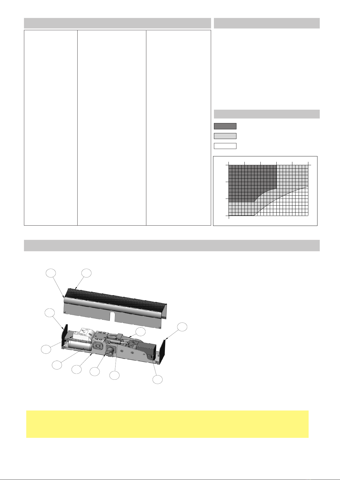
2. 2.Technical data
2.1 Use
2.2 Conditions of use
pag. 3
3. 3. References pag. 3
4. Installazione automazione
4. Automation installation
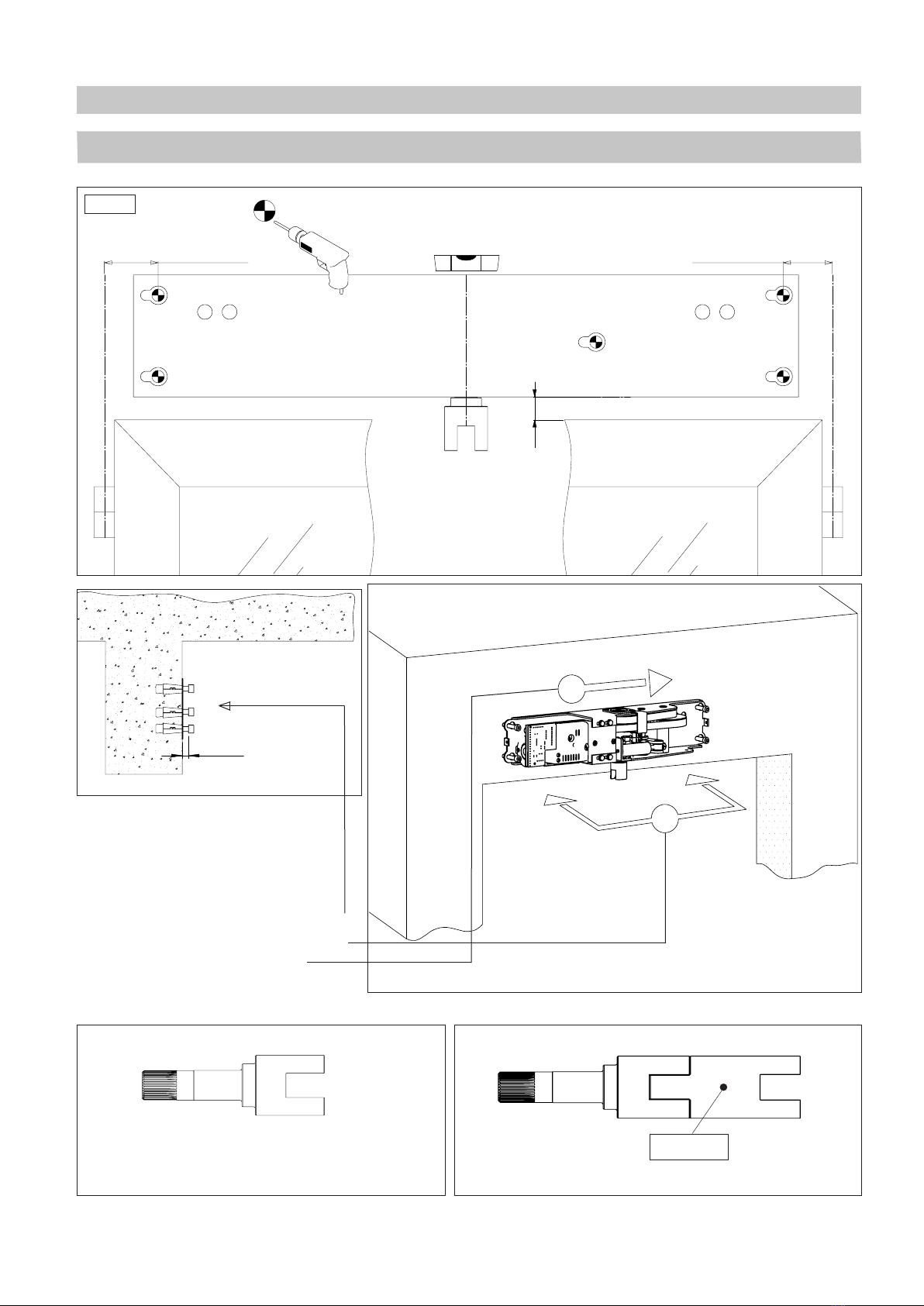
4.1 Positioning of drills to fasten SMARTONE automation with articulated arm (01FE0055)
4.2 Installation with articulated arm
4.3 Articulated arm for hinged door COD. 01FE0055
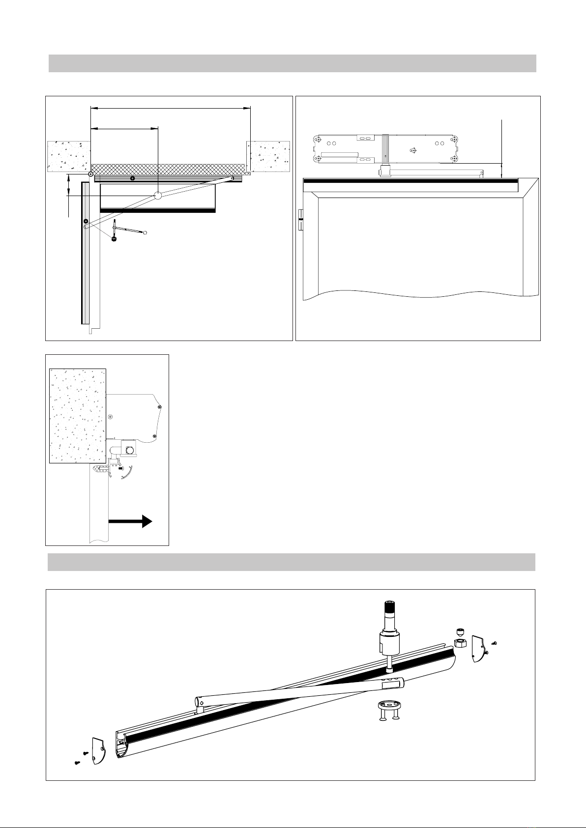
4.4 Positioning of drills to fasten SMARTONE automation with sliding arm (01FE0056)
4.5 Installation with sliding arm 01FE0056
4.6 Sliding arm for hinged door COD. 01FE0056
pag. 4
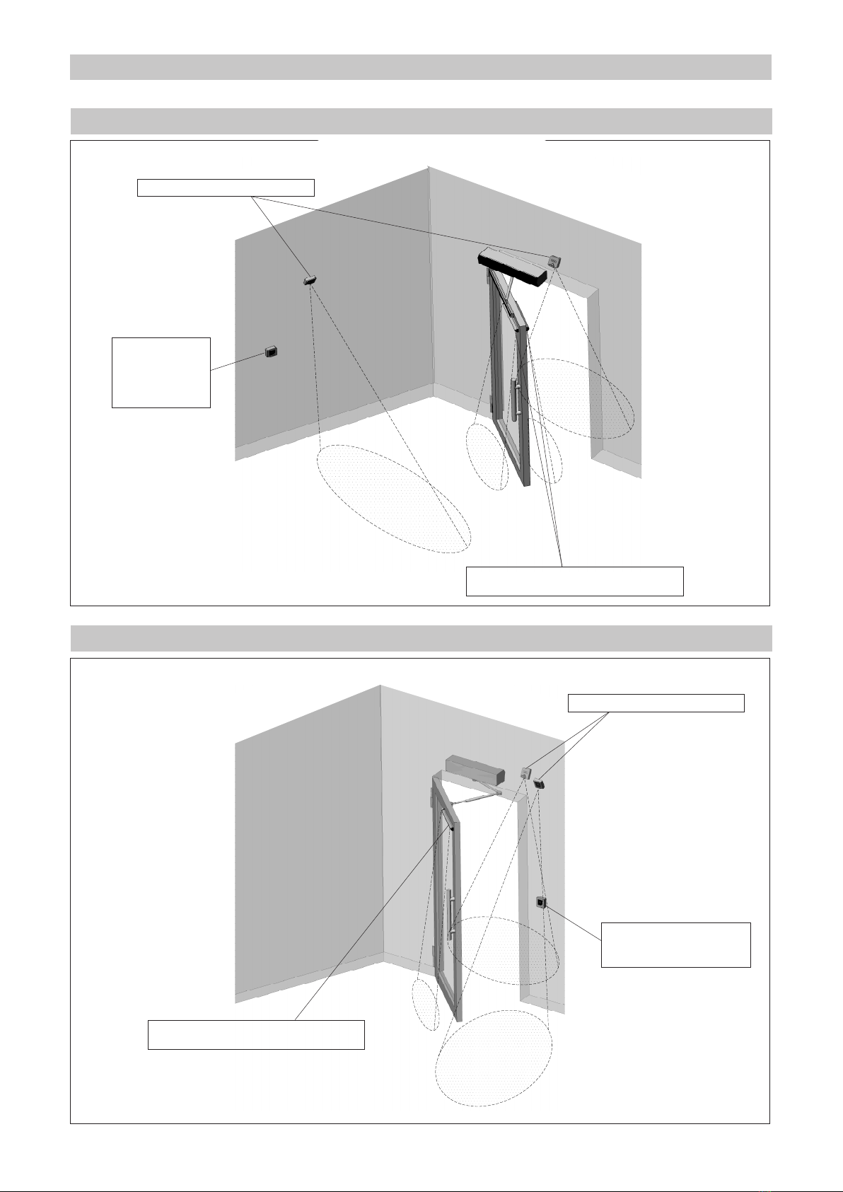
5. Application samples
5.1 Sliding arm hinged door COD. 01FE0056
5.2 Articulated arm hinged door COD. 01FE0055
5.3 Parallel of two automations, overlapping leaves
5.4 Parallel of two automations, rebated leaves
pag. 8
6. Limit switches adjustment and opening safety pag. 10
7. Connections pag. 11
8. Commands and power supply for accessories pag. 12
9. Operating
9.1 Auto-set and automatic closure time regulation
pag. 13
10. Accessories’ electrical connections samples
10.1 Wired rotating selector electrical connection
10.2 Soft touch / mobility-impaired soft touch electrical connection
pag. 14
11. Control terminal descriptioni pag. 15
12. SMARTONE hinged doors instruction manual
12.1 General safety advices
pag. 16
13. Maintenence book pag. 17
1. Safety warnings
In order to protect the safety of people, follow all the instructions carefully. An incorrect installation or use of the
product may lead to serious damage to people. Read carefully the instructions before starting to install the product.
The packaging materials (plastic, polystyrene, etc.) must not be left within reach of children as they are potential sources
of danger. Keep the instructions for future references. This product has been designed and built exclusively to be used as
indicated in this document. Any other use that is not explicitly indicated could compromise the product integrity and/or repre-
sent a source of danger. Before starting the installation, check the product integrity. Do not install the product in explosive
environments and atmospheres: the presence of ammable gases or fumes represents a serious danger for safety. Before
installing the motors, make all the structural changes related to safety clearances and to the protection or segregation of all
the areas in which there is risk of being crushed, cut or dragged, and danger areas in general.
Make sure the existing structure is up to standard in terms of strength and stability.
The motor manufacturer is not responsible for failure to use Good Working Methods when building the frames to be motorized
or for any deformation occurring during use. The safety devices (photocells, safety edges, emergency stops, etc.) must be in-
stalled taking into account: the regulations and directives in force, Good Working Methods, the installation area, the operation
logic of the system and the forces developed by the motorized door.
Apply the hazard area notices required by applicable regulations.
Each installation must clearly show the identication details of the motorized door.
CAUTION:
1.1 Machinery directive
Manufacturer: MYONE S.r.l
Address: Via T. Edison, 11 - 30035 - Mirano - Venice – ITALY
Declares that: The automation for hinged door mod. SMARTONE
has been built in order to be incorporated into machinery or to be assembled with other machinery to constitute machinery covered by Direc-
tive 2006/42/EC;
is in conformity with the essential safety requirements of the following additional EC directives:
• 2006/95/EC Low Voltage Directive.
• 2004/108/EC Electromagnetic Compatibility directive.
Furthermore, it declares that it is not allowed to put the machinery into service until the machinery into which it is to be incorporated or of
which it is to be a component has been identied and declared to be in conformity with the provisions of Directive 2006/42/EC and subse-
quent amendments.
Mirano, 23 July 2013 Daniele Vanin
(General Manager)