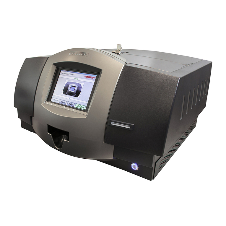
Magtek EXPRESSCARD 1000 User manual


ii
Edition: March 2008
This publication is subject to change without notice and may contain technical inaccuracies or graphical
discrepancies. Changes or improvements made to this product will be updated in the next publication
release. No part of this document may be reproduced or transmitted in any form or by any means,
electronic or mechanical, for any purpose, without the express written permission of MagTek, Inc.
Copyright
©
2007 - 2008
MagTek is a registered trademark of MagTek, Inc.
ExpressCard 1000
™
is a trademark of MagTek, Inc.
MagnePrint
™
is a trademark of MagTek, Inc.
Windows is a registered trademark of Microsoft Corporation.
All other system names and product names are the property of their respective owners.
Printed in the United States of America
REVISIONS
Rev Number Date Notes
1.01 09 Jan 2008 Initial Release
2.01 04 Mar 2008 Image updates, headers and general corrections

iii
Table of Contents
Section 1: General Information .................................................................................................. 1
1.1: Safety Information........................................................................................................... 1
1.2: Identification Information ................................................................................................. 1
1.3: Product Specifications..................................................................................................... 3
Electrical............................................................................................................................. 3
Acoustics ............................................................................................................................ 3
Environment ....................................................................................................................... 3
Communications................................................................................................................. 3
Dimensions......................................................................................................................... 3
Magnetic Stripe Encoding................................................................................................... 3
Embossing.......................................................................................................................... 3
Card and Printing ............................................................................................................... 4
Section 2: Installation & Operation ............................................................................................ 7
2.1: Loading Ribbon............................................................................................................... 7
2.2: Loading Cards................................................................................................................. 9
2.3 User Interface ................................................................................................................ 10
2.4: Network Configuration................................................................................................... 11
2.5: Calibration..................................................................................................................... 14
2.6: Printing a Test Card ...................................................................................................... 18
2.7: Security ......................................................................................................................... 19
2.8: Changing Default Password.......................................................................................... 22
Section 3: Service Procedures ................................................................................................ 23
3.1: Tools and Materials....................................................................................................... 23
3.2: Handling ESD-Sensitive Parts ...................................................................................... 24
3.3: Maintenance ................................................................................................................. 25
Lubrication........................................................................................................................ 25
Print Head Cleaning ......................................................................................................... 25
Cleaning the Platen and Card Feed Rollers ..................................................................... 25
3.4: Firmware Update........................................................................................................... 27
3.5: Software........................................................................................................................ 28
Updates via the Internet ................................................................................................... 28
Activation.......................................................................................................................... 31
3.6: Adjustments .................................................................................................................. 33
Y-axis Alignment for Printer Card Handoff........................................................................ 33
Adjusting Printer XY Handoff............................................................................................ 34
Tuning Embosser Position................................................................................................ 36
How to Align the Embossed Characters and Printed Image............................................. 39
X_SPI Adjustment ............................................................................................................ 41
Hammer Follower Adjustment .......................................................................................... 42
Embossed Character Height ............................................................................................ 45
3.7: Diagnostic Information .................................................................................................. 48
3.8: Diagnostic Utilities......................................................................................................... 49

iv
Sensor .............................................................................................................................. 50
XY Mover.......................................................................................................................... 50
Embosser ......................................................................................................................... 51
MCP Commands .............................................................................................................. 51
3.9: Common Error Messages ............................................................................................. 54
Section 4: Removal and Replacement .................................................................................... 57
4.1: Covers........................................................................................................................... 57
4.2: Embosser Assembly ..................................................................................................... 62
4.3: XY Assembly................................................................................................................. 64
4.4: Exit Assembly................................................................................................................ 66
4.5: Printer Assembly ........................................................................................................... 68
Printhead Replacement .................................................................................................... 70
Setting the Print TOF........................................................................................................ 72
Setting the Print EOF........................................................................................................ 73
Adjusting the Image Darkness.......................................................................................... 74
Adjusting the Vertical Image Position from the Driver....................................................... 74
4.6: Sliding Tray Assembly................................................................................................... 75
4.7: 24-Volt Power Supply.................................................................................................... 81
4.8: MagnePrint Swipe Reader (MSR) Rail.......................................................................... 82
4.9: Monitor Replacement .................................................................................................... 83
Section 5: Parts Catalog .......................................................................................................... 87
5.1: Covers Assembly .......................................................................................................... 88
Top Cover......................................................................................................................... 89
Front Cover with Display .................................................................................................. 90
Left Cover......................................................................................................................... 91
Left Top Cover Latch Assembly ....................................................................................... 92
Right Cover ...................................................................................................................... 93
Right Top Cover Latch Assembly ..................................................................................... 94
Card Access Door Latch Assembly .................................................................................. 95
5.2: Chassis Assembly......................................................................................................... 96
Outer Components of Chassis ......................................................................................... 97
Inner Components of Chassis .......................................................................................... 98
5.3: Embosser Assembly ................................................................................................... 100
Top Half of Embosser..................................................................................................... 101
Embosser Wheel ............................................................................................................ 103
Bottom Half of Embosser................................................................................................ 104
Embosser Base .............................................................................................................. 106
5.4: X-Y Transport Assembly ............................................................................................. 107
Y Portion of Assembly .................................................................................................... 108
XY Carriage.................................................................................................................... 110
Card Clamp Assembly.................................................................................................... 112
5.5: Exit Transport Assembly ............................................................................................. 114
Eject Card Slide.............................................................................................................. 115
Card Transport (Left Side).............................................................................................. 116
Card Transport (Right Side) ........................................................................................... 118
Card Transport (Center) ................................................................................................. 120

v
5.6: Printer Assembly ......................................................................................................... 122
5.7: Sliding Tray Assembly................................................................................................. 123
Section 6: Cabling Diagram Index ......................................................................................... 125
Appendix A ............................................................................................................................ 185
Acronyms ........................................................................................................................... 185
Accessory Items................................................................................................................. 186
Optional Components: ....................................................................................................... 186
Supplies ............................................................................................................................. 186
Technical Support .............................................................................................................. 186

vi
FCC WARNING STATEMENT
This equipment has been tested and found to comply with the limits for Class A digital device, pursuant
to Part 15 of FCC Rules. These limits are designed to provide reasonable protection against harmful
interference when the equipment is operated in a residential environment. This equipment generates,
uses, and can radiate radio frequency energy and, if not installed and used in accordance with the
instruction manual, may cause harmful interference to radio communications. However, there is no
guarantee that interference will not occur in a particular installation.
FCC COMPLIANCE STATEMENT
This device complies with Part 15 of the FCC Rules. Operation of this device is subject to the following
two conditions: (1) this device may not cause harmful interference. And (2) this device must accept any
interference received, including interference that may cause undesired operation.
CANADIAN DOC STATEMENT
This digital apparatus does not exceed the Class B limits for radio noise for digital apparatus set out in
the Radio Interference Regulations of the Canadian Department of Communications.
Le présent appareil numérique n’émet pas de bruits radioélectriques dépassant les limites applicables
aux appareils numériques de las classe B prescrites dans le Réglement sur le brouillage
radioélectrique édicté par les ministère des Communications du Canada.
CE STANDARDS
Testing for compliance to CE and FCC requirements was performed by an independent laboratory.
The unit under test was found compliant to Class B.
US/CANADA
This product is listed per Underwriter Laboratories and 60950-1, and CSA C22.2 No. 60950-1-03.

1
Section 1: General Information
1.1: Safety Information
The information within this manual has been prepared for use by trained professional service
personal and is not intended for general use. To maintain the safety and integrity of the
machine it is essential that procedures laid out within this manual are followed.
CAUTION: Disconnect power from the ExpressCard 1000 (EC1000) before you connect
or disconnect any cable, electronic board or assembly for your personal safety and to
prevent damage to the machine.
1.2: Identification Information

ExpressCard 1000 Hardware Service Manual
2

Section 1: General Information
3
1.3: Product Specifications
Electrical
• 100 to 240 VAC at 50 to 60 Hz, 2 Amps
Acoustics
Idle (standby mode): 66 dB
Printing: 76 dB
Environment
Printer temperature and humidity
• Operating
– Temperature: 65° F to 80° F
– Relative humidity: 20 to 80 percent non-condescending
• Storage environment (unpacked)
– Temperature: 30°F to 100° F
– Relative humidity: up to 90%
Communications
The EC1000 uses a standard RJ45, CAT5 connector to communicate with local area
networks. Port speed and communication protocols can be adjusted to accommodate
network requirements, for further details refer to the EC1000 software manual.
Dimensions
Length: 24.25in Height: 15.13in Width: 26.77in Weight: 80lbs.
Magnetic Stripe Encoding
MSR Read-data Format
Specifications Supported
Mag-Stripe: ANSI/ISO/AAMVA/CDL/ for tracks 1, 2, and 3
Smart Card: ISO 7816-1, -2, and -3
Embossing
The EC1000 is designed to use card stock that meets the specifications listed in the ISO and the IEC
publications: 7810, 7811-1 through 6.
Card Warpage:
When lying convex side up on a flat rigid surface, the maximum distance between the surface and the non-
embossed portion of the card should not be larger than 2.5mm (0.10in.) including the card thickness.
Character Spacing:
Character spacing should be 2.45mm ± 0.15mm (0.100in. ± 0.006in)

ExpressCard 1000 Hardware Service Manual
4
Height of Embossed Characters:
NOTE: The height of embossed character is measured from the non-embossed surface of the card to the
highest point on the embossed character (optimum character height is 0.46mm /0.018in).
Visually and machine readable characters Visually readable characters
Used Maximum Minimum Maximum Minimum
cards 0.48mm 0.40mm 0.46mm 0.36mm
0.019in 0.016in 0.018in 0.014in
Returned 0.48mm 0.30mm 0.46mm 0.26mm
cards 0.019in 0.012in 0.018in 0.010in
Card and Printing
Term Description
Accepted Standard
Card Sizes
•CR-80 (3.370"L x 2.125"W / 85.6mmL x 54mmW)
•CR-79 Adhesive Back (3.303"L x 2.051"W / 83.9mmL x 52.1mmW)
Accepted Card
Thickness
•Print only: .020" (20 mil) to .050" (50 mil) / .508mm to 1.27mm(single-
sided printing only for 50 mil cards)
•Print/Lamination: .030" (30 mil) to .040" (40 mil) / .762mm to 1.02mm
Accepted Card
Types
PVC or polyester cards with polished PVC finish; monochrome resin required fo
r
100% polyester cards; optical memory cards with PVC finish
Accepted Card
Compositions
PVC or polyester cards with polished PVC finish; monochrome resin required fo
r
100% polyester cards.
Barcodes PVC or polyester cards with polished PVC finish; monochrome resin required fo
r
100% polyester cards.
Input Hopper Card
Capacity
Dual-stack Hopper, 200 cards (30 mil); auto or manual feed
Card Eject Bin 11 cards (30 mil)
Card reject Bin 18 cards (30 mil)
Colors Up to 16.7 million colors / 256 shades per pixel
Duty Cycle 50 cards per day (1500 cards per year)
Fonts TrueType fonts are available via the Windows driver.
Over laminate
Options (for LC)
•Thermal Transfer Over laminate, .25 mil thick
•PolyGuard Over laminate, 1.0 mil and .6 mil thick
•All over laminates available in clear, standard holographic design o
r
custom holographic design.
•PolyGuard available in a CR-80 patch size
Print Area •CR-80 edge-to-edge (3.37"L x 2.11"W / 85.5mmL x 53.5mmW)
•CR-79 (3.303"L x 2.051"W / 83.9mmL x 52.1mmW)
Printing Method Dye-Sublimation/Resin Thermal Transfer
Printing Resolution 300 dpi (11.8 dots/mm)

Section 1: General Information
5
Term Description
Print Speed –
Batch Mode
•K: 7 seconds per card/514 cards per hour*
•BO: 12 seconds per card/300 cards per hour*
•YMCKO: 25 seconds per card/144 cards per hour*
•YMCKOK: 33 seconds per card/109 cards per hour* YMCKK
(w/Lamination): 35 seconds per card /102 cards per hour*
Indicates the Print Ribbon type and the number of Ribbon panels printed
where Y=Yellow, M=Magenta, C=Cyan, K=Resin Black, B=Dye-Sublimation
Black and O=Overlay.
Print speeds do not include the time needed for the PC to process the
image.
Process time is dependent on the size of the file, the CPU, amount o
f
RAM and the amount of available resources at the time of the print.
Print speed indicates an approximate batch print speed and is measured
from the time a card feeds into the Printer to the time it ejects from the
Printer. (Note: The single card print speeds will be slower than the batch
print speeds listed above since batch print speed is enhanced by the
Printer's multi-tasking capabilities when printing multiple cards in
succession.)
Card Printing
Temperature
65° to 80°F / 18° to 27°C
Printer Humidity 20% to 80% non-condensing

ExpressCard 1000 Hardware Service Manual
6

7
Section 2: Installation & Operation
Remove the EC1000 from its shipping container and inspect the unit for any possible shipping
damage. Place the EC1000 on a flat level surface (capable of supporting at least 85lbs.) then
remove all shipping restraints within and outside of the machine. Next, connect the power and
data cables. Power up the EC1000 via the power switch on the rear chassis and allow the
system to startup. After the EC1000 starts up the ribbon will need to be loaded if card printing
is planned.
2.1: Loading Ribbon
Follow these steps to load ribbon into the Printer:
1) Remove the ribbon and cleaning roller from its packaging. Do not touch the colored
portion of the ribbon. Oil or dirt from the hands can impair print quality.
2) The supply end of the ribbon is the side with the fresh, unused ribbon. The ribbon take-
up is the other end. The gray cores must be present in the supplied ribbon in order for
the printer to print properly.
3) Open the Top Cover of the EC1000 by inserting and turning the key and gently grasping
the top handles of the Cover and lifting upward. The cover will lift up and fold in half
exposing the printer beneath. (A user password will also be needed to open electronic
locks on the cover)
4) Open the Print head assembly by gently pulling up on the assembly’s release tab and
lifting upwards. This will allow the assembly to swing completely open.
5) Place the supply end of the ribbon in between the green and gray ribbon drive hubs
located on the right-hand side of the printer’s interior (match the green ring to the green
ring). Make certain that the ribbon is fed from underneath the ribbon roll. Hint: The
ribbon drive hub is on the right side of the printer, as you are looking into the EC1000
from the front side. Use the end of the ribbon supply core to push in this ribbon drive
hub when inserting the ribbon. Place the take-up end of the ribbon roll in between the
two gray ribbon drive hubs located on the left-hand side of the printer’s interior. Load the
ribbon take-up end just as you loaded the ribbon supply end.
6) When loaded properly, the ribbon should feed underneath both ends of the ribbon roll.
Grasp the release tab and gently lower the print head assembly to close it.
7) Every time the ribbon is replaced the card cleaning cartridge must also be replace. To
replace the card cleaning cartridge lift the cleaning assembly out of the printer.
8) Once the assembly has been removed replace the card cleaning roller and remove the
protective tape on the new roller. Then reinstall the card cleaning assembly into the
printer.

ExpressCard 1000 Service Manual
8
9) Close the EC1000’s top cover. When you start to print, the ribbon drive hubs will
automatically engage the notches on both cores of the ribbon roll.
Note: If the printer has difficulty recognizing the installed ribbon a calibration of the
printer maybe needed. Refer to the calibration section for instructions.

Section 2: Installation & Operation
9
2.2: Loading Cards
Caution: Never run cards with a contaminated, dull or uneven surface through the Printer.
Printing onto such cards will ultimately lead to poor print quality and will greatly reduce the life
of the Print head. Additionally, always store the card stock in its original packaging or in a
clean, dust-free environment. Do not print on cards which have been dropped or soiled. Print
heads damaged by contaminated or poor quality cards will automatically void the print
head’s factory warranty.
The EC1000 holds a maximum of 100 CR-80 size cards in each Card Input Hopper. It will
automatically feed each card off the bottom of the stack unless a single card is placed into the
manual feed slot. To load the cards into the printer, refer to the following steps:
1) Open the EC1000 card door cover via the touch screen once electronic locks open you
will have ten seconds to open door before locks reengage (see Security section).
2) Remove a stack of 100 or fewer cards from the card packaging. Do not touch the area
of the cards on which you intend to print. Oil or dirt from the hands can impair print
quality. Handle cards only along the edges.
3) Load the stack of cards into the EC1000 card input tray and pushing the stacks all the
way to the back of the card input hoppers. Always load cards with the top or primary
print side facing up. If inserting cards with a magnetic stripe be sure the magnetic stripe
is positioned downward and that the stripe is oriented toward the rear of the EC1000. If
inserting smart cards, be sure the end of the card containing the smart card chip is
inserted first.
4) Once the cards have been inserted, remove the top card and throw it away if you
suspect it has been contaminated with oil from the fingertips.
5) Before the card door is closed make sure that you place the card weight with the arrow
facing up on top of the card stack to insure proper feed by the printer.
Additional Notes:
•If the card weight is not placed on the card stock properly (arrow side up and
facing inward) there will be card jams.
•Check for static build up between cards. Occasionally, a static charge will
build up between the surfaces of two or more cards causing them to stick
together.
•Reduce or eliminate this static charge by separating the cards manually before
placing them in the input Hopper.

ExpressCard 1000 Service Manual
10
2.3 User Interface
Below is the default display for the EC1000. From this screen the system will indicated its
current status along with any error that prevents normal operation. When the system displays
Offline it will not process a card. In addition to determine the firmware version on the machine
select the Help button and it will be displayed.
The menu screen is where operators or service personal are able to gain access to the user
and service functions of the machine. The specific functions of each button are discussed in
the relevant sections.

Section 2: Installation & Operation
11
2.4: Network Configuration
By default the EC1000 will obtain an IP address automatically however, for most
networks the IP address must be statically set. To configure the network interface on
the EC1000 follow the steps below to configure the network card:
1. Touch the Menu button on the system ready screen.
2. Select the TCP/IP on the next screen.

ExpressCard 1000 Service Manual
12
3. After selecting the TCP/IP button, two operator passwords must be entered on the
screen shown.
4. Once the correct passwords have been entered the screen below will be displayed. At
this point, enter the IP address, gateway and subnet of the network you are connecting
to. If the network information is not known contact the network administrator.

Section 2: Installation & Operation
13
If a subnet is not entered when configuring the IP address then the error below will be shown.
5. After the network configuration has been entered (shown below) press the set new
button on the screen, the network card configuration is now complete. To exit back to
the system ready screen press the Status button.
Other manuals for EXPRESSCARD 1000
4
Table of contents
Other Magtek Printer manuals

Magtek
Magtek ExpressCard 3000 User manual

Magtek
Magtek EXPRESSCARD 1000 User manual

Magtek
Magtek ExpressCard 3000 Manual

Magtek
Magtek ExpressCard 2000 Operating instructions

Magtek
Magtek ExpressCard 500p User manual

Magtek
Magtek ExpressCard 500 User manual

Magtek
Magtek ExpressCard 2000 User manual

Magtek
Magtek ExpressCard 500p Use and care manual

Magtek
Magtek ExpressCard 500p User manual

Magtek
Magtek ExpressCard 2000 Manual