SEWOO SLK-TL20X Series User manual
TE20X Series ENG Rev. 07/2023
Aroot Co., Ltd.
28-6, Gajangsaneopdong-ro, Osan-si, Gyeonggi- do, 18103, Republic of Korea
TEL : +82-31-8077-5000 / FAX : +82-31-624-5310
http://www.miniprinter.com
All specications are subject to change without notice
MODEL : SLK-TL20X Series
Receipt Printer User’s Manual
This device co mplies with part 15 of the FCC Rules.
Operation is subject to the following two conditions.
1) This device may not cause harmful interference, and
2) This device must accept any interference received,
including interference that may cause undesired operation.
Vic Barczyk
20280 S. Vermont Ave. STE 200, Torrance, CA 90502 | USA
+310-561-8030
Victor Almazan
Paseo de la Reforma No. 265 Piso 2.Ocina SBC. Col.
Cuauhtémoc, C.P. 06500 Ciudad de Mexico | Mexico
LA_Sales@miniprinter.com
Disposal of Old Electrical&Electronic Equipment(Applicable in the European Union and other Euro-
pean countries with separate collection systems)
This symbol on the product or on its packaging indicates that this product shall not be treated as household
waste. Instead it shall be handed over to the applicable collection point for the recycling of electrical and
electronics equipment. For more detailed information about recycling of this product, please contact your
local city oce, your household waste disposal service or the shop where you purchased the product.

10. Printer Cleaning 21
11. Linerless Printer 22
11-1. Linerless Printer Cleaning 22
11-2. Recommended Paper 22
12. Specications 23
13. Command List 25
14. Utilities 27
15. SW 28
Table of Contents
1. Parts Identications 3
2. Setting up the printer 4
2-1. Unpacking 4
2-2. Connecting the cables 5
2-2-1. Interface Connector 6
2-2-2. Cash Drawer Connector 8
2-3. Loading the Roll paper 9
2-4. Adjustment of paper width 12
3. Control panel and other functions 13
3-1. Control panel 13
3-2. Error indicators 13
4. Self Test 14
5. ASCII Print 15
6. ECO Mode 15
6-1. Font 15
6-2. Paper Reduce 16
6-3. Density 16
7. Printer Setting 17
7-1. Baudrate 17
7-2. Cutter 17
7-3. Error Beep 17
7-4. Melody 18
8. Hexadecimal Dump 19
9. Peripherals Connection 20
9-1. Bluetooth Connection (Option) 20
9-2. Wi-Fi Connection (Option) 20

4
34
3
2. Setting Up the Printer
2-1. Unpacking
Your printer box should include these items. If any items are damaged or missing, please contact
your dealer for assistance.
The Printer CD Roll Paper
Interface Cable(optional) Adaptor(Optional)
Cleaning pen(Optional)
1. Parts Identications
POWER SWITCH
COVER OPEN LEVER
CONTROL PANEL
Used to turn on/off
power to the printer.
Pull down this lever to
open the printer cover.
Features LED indicators to indicate printer
status and switches to operate the printer.
PRINTER COVER
Open this cover to
load or replace paper.
6
56
5
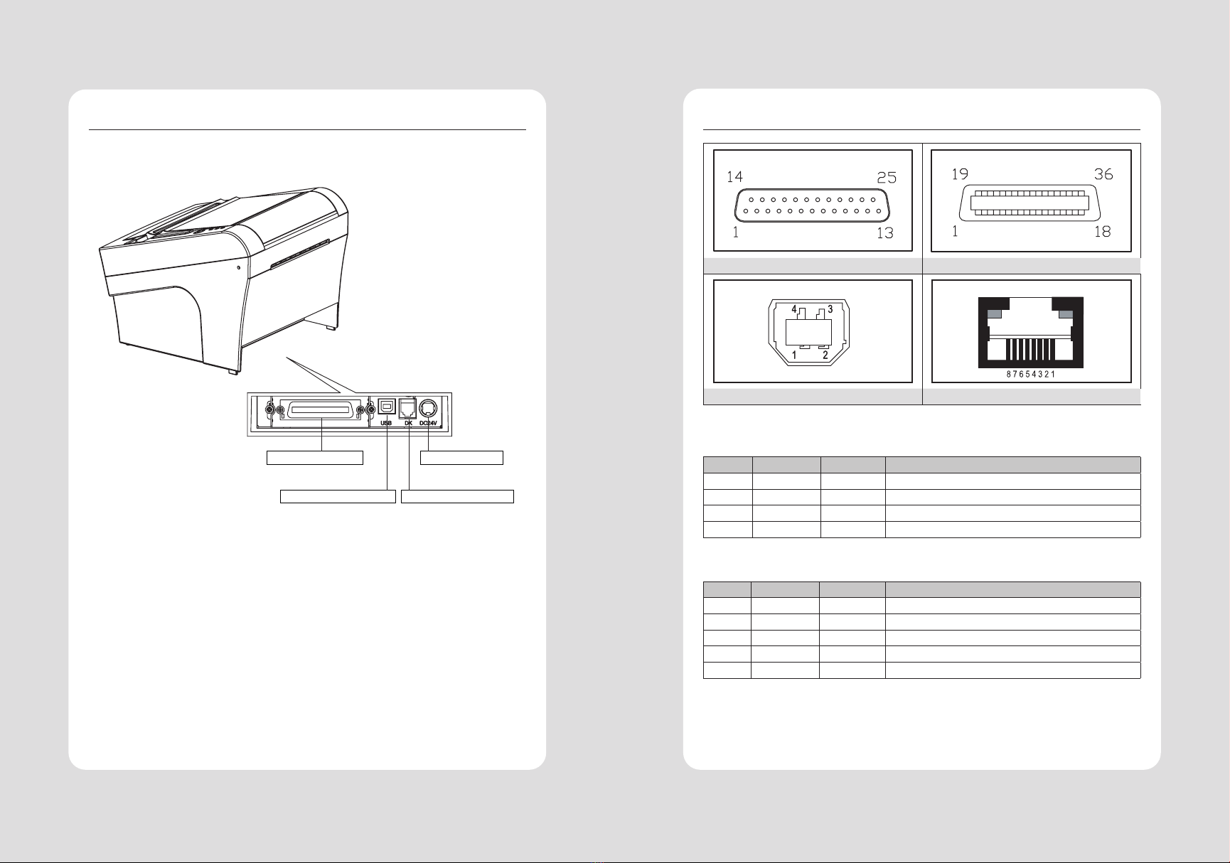
2-2-1. Interface Connector
D-SUB 25 Female Serial Centronics Parallel
Link LED Status LED
USB “B” Type Ethernet
USB Interface
PIN SIGNAL I/O DESCRIPTION
1 +5V - +5V
2DATA- - Printer transmit data line
3DATA+ - Printer transmit data line
4 GND - System Ground
Serial Interfaced
PIN SIGNAL I/O DESCRIPTION
2TxD Output Printer transmit data line RS-232C level
3 RxD Input Printer receive data line RS-232C level
4, 20 DTR Output Printer handshake to host line RS-232C level
6 DSR Input Data Send Ready
1, 7 GND - System Ground
2-2. Connecting the Cables
You can connect up the cables required for printing to the printer.
They all connect to the connector panel on the back of the printer, which is shown below :
INTERFACE CONNECTOR POWER CONNECTOR
CASH DRAWER CONNECTOR
INTERFACE CONNECTOR(USB)
Before connecting any of the cables, make sure that both the printer and the computer are turned
o.

8
78
7
2-2-2. Cash Drawer Connector
The printer can operate two cash drawers with a 6 pin RJ-11 modular connector.
The driver is capable of supplying a maximum current of 1.0 A for 510ms or less when not printing.
PIN SIGNAL Description
1Signal GND -
2Drawer kick-out drive signal 1 Output
3Drawer open/close signal Input
4+24V -
5Drawer kick-out drive signal 2 Output
6Signal GND -
Centronics Parallel Interface
PIN SIGNAL I/O DESCRIPTION
1 STROBE- Input Synchronize signal Data received
2~9 DATA0~7 Input/
Output Data bit Transmitted 0~7
10 ACK- Output Data receiving completed.
11 BUSY Output Impossible to print of data receiving.
12 PE Output Paper empty
13 SELECT Output Printer status for ON/OFF line
14 AUTO FEED- Input Paper auto feed signal
15 GROUND - System ground
16 GROUND - System ground
17 NC -
18 LOGIC-H - +3.3V
19~30 GROUND - System ground
31 INIT- Input Initialize
32 ERROR- Output Printer error
33 GROUND - System ground
34 NC -
35 NC -
36 SELLECT IN- Input Printer select signal
Ethernet Interface
PIN SIGNAL I/O
1 Data Out + Output Data +
2 Data Out - Output Data -
3 Data IN + Input Data +
4N.C
5N.C
6 Data IN - Input Data -
7N.C
8N.C
10
910
9
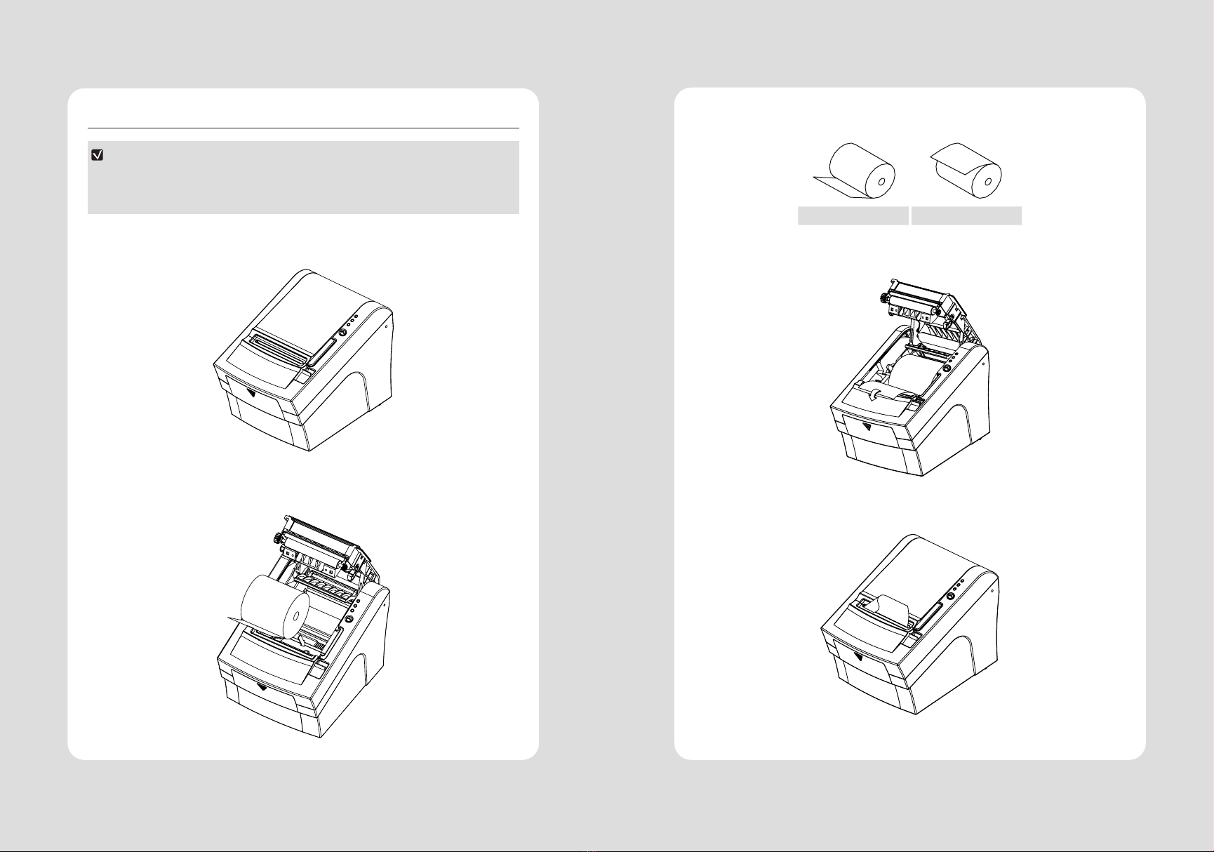
5 Be sure to note the correct direction that the paper comes o the roll.
X O
6 Pull out a small amount of paper, as shown. Then, close the cover.
7 Tear o the paper as shown.
2-3. Loading the Roll paper
NOTE
Be sure to use paper rolls that meet the specications. Do not use paper rolls that have the
paper glued to the core because the printer cannot detect the paper end correctly.
(Turn o power switch)
1 Make sure that the printer is not receiving data; Otherwise, data may be lost.
2 Open the paper roll cover by pushing down the cover open button.
3 Remove the used paper roll core if there is one inside.
4 Insert new paper roll as shown.

12
11 12
11
2-4. Adjustment of paper width
1 Please adjust the Paper Guide to t to the paper width as the direction of arrow.
2 Tight the screw after adjusting the Paper Guide.
3 Pull the edge of paper once the paper roll is installed correctly and close the Paper Cover.
CAUTION:
When the paper is jammed with cutter, the top cover might be stuck. In this case, repeat power on
and o several times.
If the top cover is still stuck, please follow the steps to release the papers from jamming.
1 Make sure the printer is turned o.
2 Take out DIP switch cover as shown.
3 Turn screw with drivers to a direction until paper is released from the cutter.

14
13 14
13
4. Self Test
The self-test result indicated whether the printer is operating properly. Also with this, user can
check following options or status of the printer.
Control circuit
Printer mechanism
Printing quality
ROM version
Interface setting
This test is independent of any other equipment or software.
Running the self test
1 Make sure the printer is turned o and the printer cover is closed properly before performing
the self test.
2 Turn the printer on holding the FEED button, then the self-test will start.
The self-test prints the printer setting value and then prints the following, and pauses. (Error
LED On)
SELECT MODE BY BUTTON
1. ASCII PRINT
2. SELECT BAUDRATE MODE
3. HEXADUMP MODE
3 Press the FEED button consecutively (1~3)
1. ASCII PRINT
(press the FEED button once)
Printing test page constructed with ACII code.
2. SELECT BAUDRATE MODE
(press the FEED button twice)
Set the speed of Serial Interface
(You can set the BAUDRATE in this mode)
3. PRINTER SETTING
(press the FEED button triple time)
Set the printer option.
(Serial baudrate, Cutting mode, Error beep, Melody)
3. HEXADUMP MODE
(press the FEED button quad time)
Printing the HEX value received from the interface
※ Wait for 5~6 seconds if you want to exit. Printer performs a cutting when exiting this mode
4 The printer is ready to receive data after nishing setting.
3. Control panel and other functions
3-1. Control panel
You can control the basic paper feeding operations of the printer with the button on the control
panel. The indicator lights help you to monitor the printer’s status.
Control Panel
Button
The button can be disabled by the ESC c 5 command.
Press the FEED button once to advance paper one line. You can also hold down the FEED button
to feed paper continuously.
3-2. Error indicators
This section explains the dierent patterns signaled by the three LED indicators located on the top
cover of the printer.
STATUS
PAPER ERROR POWER
REMARKS
RED RED GREEN
Power o OFF OFF OFF Normal power is not supplied to the printer
Power on OFF OFF ON Normal power is supplied to the printer
On line OFF OFF ON Normal error-free mode
Cover open OFF ON ON Close cover
Paper empty OFF ON ON Insert new paper roll
Paper near end ON OFF ON Paper is low
Test mode OFF OFF ON Ignored error led

16
15 16
15
6-2. Paper Redue
Reduce menu (Line space, Line feed, barcode[1D] height) was developed for
paper saving.
Line space
”Line space"
means the amount of feed when you intentionally generate newlines.
Line feed
”Line feed"
means the amount of feed when there is an automatic line break.
Barcode Height
”Barcode H eight”
means the height of the barcode when creating a one-dimensional barcode.
LINE SPACE SETTING
1. NORMAL
2. REDUCE 50%
3. REDUCE 75%
4. REDUCE 90%
LINE FEED SETTING
1. NORMAL
2. REDUCE 50%
3. REDUCE 75%
4. REDUCE 90%
1D BARCODE HEIGHT SETTING
1. NORMAL
2. REDUCE 50%
3. REDUCE 75%
4. REDUCE 90%
6-3. Paper Redue
Adjust the print density to save the power consumed by the printer.
SELECT DENSITY
1. NORMAL
2. LOW
3. DARK
5. ASCII Print
6. ECO Mode
ASCII PRINT is printing a test page constructed ASCII code. You can able to check the printer works
properly with this
The ASCII PRINT test automatically ends and cuts the paper after printing the following:
*** Completed ***
The printer is ready to receive data as soon as it completes the ASCII PRINT.
After entering the ECO MODE, the list which can select the ECO option will be
printed. Similar like Self Test, you can press the FEED button to select a ECO option.
Once the input performs properly, the printer shows a result and store.
ECO MODE
1. FONT SETTING
2. LINE SPACE SETTING
3. LINE FEED SETTING
4. BARCODE[1D] HEIGHT
5. DENSITY SETTING
6-1. Font
FONT SETTING menu can be change the Font mapping(FONT A / FONT B).
If you did not want other side font, you can disable that.
- FONT A : 12x24
- FONT B : 9x17
FONT SETTING
1. FONT A -> A / FONT B -> B
2. FONT A -> B / FONT B -> B
3. FONT A -> A / FONT B -> A
4. FONT A -> B / FONT B -> A
18
17 18
17
7-4. Melody
To DK Port (Cash), Melody box or external buzzer can be connected.
You can activate it from the Melody Setting menu, and the melody will operate
after the cutting operation.
- Melody Box : Melody is xed and volume can be adjusted.
- External Buzzer : 3 types of melody are output according to the Melody Type
setting and volume control is not included
SELECT MELODY OPTION
1. MELODY SETTING
2. SELECT MELODY TYPE
MELODY SETTING
1. MELODY ON AFTER CUTTING
2. MELODY OFF
SELECT MELODY TYPE
1. MELODY-Ⅰ
2. MELODY-Ⅱ
3. MELODY-ⅢW
Change the printer settings. The options below can also be changed via the
Memory Saver.
PRINTER SETTING
1. SELECT BAUDRATE
2. SELECT CUTTING MODE
3. SELECT ERROR BEEP OPTION
4. SELECT MELODY OPTION
7-1. Baudrate
After entering the BAUDRATE MODE, the list which can select the BPS will be
printed.
Similar like Self Test, you can press the FEED button to select a BAUDRATE.
Once the input performs properly, the printer shows a result and store.
The printer is ready to receive data as soon as it completes the SELECT
BAUDRATEMODE.
SELECT BAUDRATE
1. 4800bps
2. 9600bps
3. 19200bps
4. 38400bps
5. 57600bps
6. 115200bps
7-2. Cutter
Set cutter mode.
SELECT CUTTING MODE
1. PARTIAL CUT
2. FULL CUT
7-2. Error Beep
If the cover is open or there is no paper, the error beep function is activated.
This option allows you to enable / disable the error beep.
SELECT CUTTING MODE
1. BEEP ON
2. BEEP OFF
7. Printer Setting
20
19 20
19
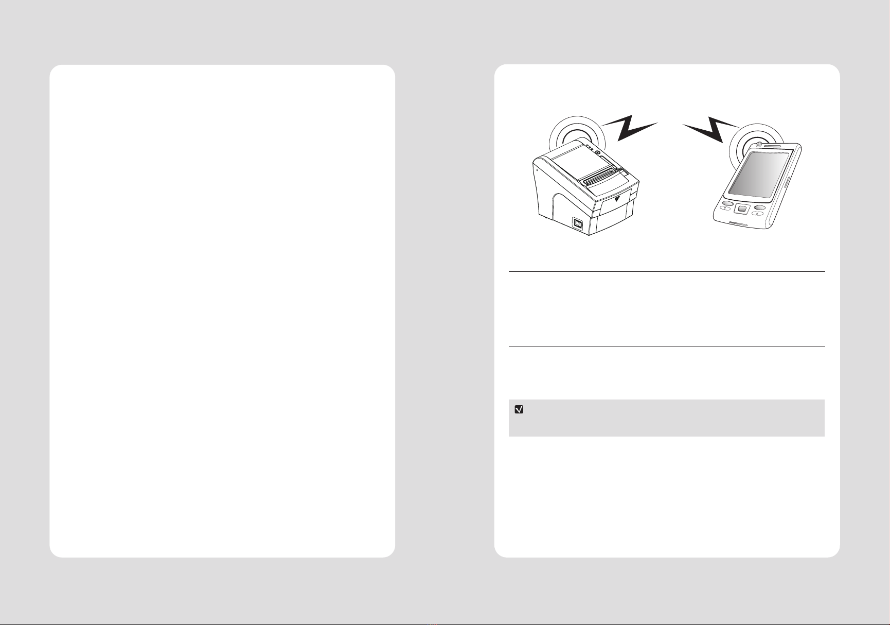
9. Peripherals Connection
This product can communicate with other devices via Bluetooth or Wi-Fi communication and
cable.
9-1. Bluetooth Connection (Optional)
1 The Printer can be connected to devices equipped with Bluetooth communication capacity
(PDAs, PCs, etc.)
2 Use the Bluetooth connection function supported by the device to connect to the printer.
9-2. Wi-Fi Connection (Optional)
1 The Printer can be connected to devices equipped with Wi-Fi communication capacity (PDAs,
PCs, etc.)
2 Use the Wi-Fi connection function supported by the device to connect to the printer.
NOTE
Please refer to the conguration manual for details.
8. Hexadecimal Dump
This feature allows experienced users to see exactly what data is coming to the
printer. This can be useful in nding software problems.
When you go into the hex dump function, the printer prints all commands and other
data in hexadecimal format along with a guide section to help you nd specic com-
mands.
To use the hex dump feature, follow these steps
1 Please turn printer o.
2 Please turn printer on while press down “FEED” button.
3 Press the FEED button three times when the Self Test printed.
4 Now printer had entered into Hexa dump mode.
5 Run any software program that sends data to the printer. The printer prints
”Hexadecimal printing mode…” and then all the codes it receives in a two-column
format. The rst column contains the hecadecimal codes and the second column
gives the ASCII characters that correspond to the codes.
Hecadecimal Dump
1B 21 00 1B 26 02 40 40 .!..& . @ @
1B 25 01 1B 63 34 00 1B .%..c4 ..
41 42 43 44 45 46 47 48 ABCDEFGH
A period (.) is printed for each code that has no ASCII equivalent.
6 Turn o the printer.
7 Turn on the printer.
22
21 22
21
11. Linerless Printer
11-1. Linerless Printer Cleaning
Paper dust or impurities inside the printer may cause printing problems. Please clean as below.
1 Open the printer cover and clean the paper PASS part.
2 Remove the paper if it is jammed.
3 Remove impurities from cutter blade with cleaning pen or alcohol.
4 Wipe the printer head and roller with cleaning pen.
5 Wipe the paper detection sensor with a cotton swab or cloth.
6 When using linerless paper, please perform cleaning before using 30 Rolls or within a week.
NOTE
If the adhesive builds up due to poor cleaning, printing problems may occur.
11-2. Recommended Paper
MAX International Converters, Inc. MAXStick Products Ltd(USA)
WARNING
We are not responsible for any paper use issues other than recommended paper,
which may result in poor print quality or damage to the product.
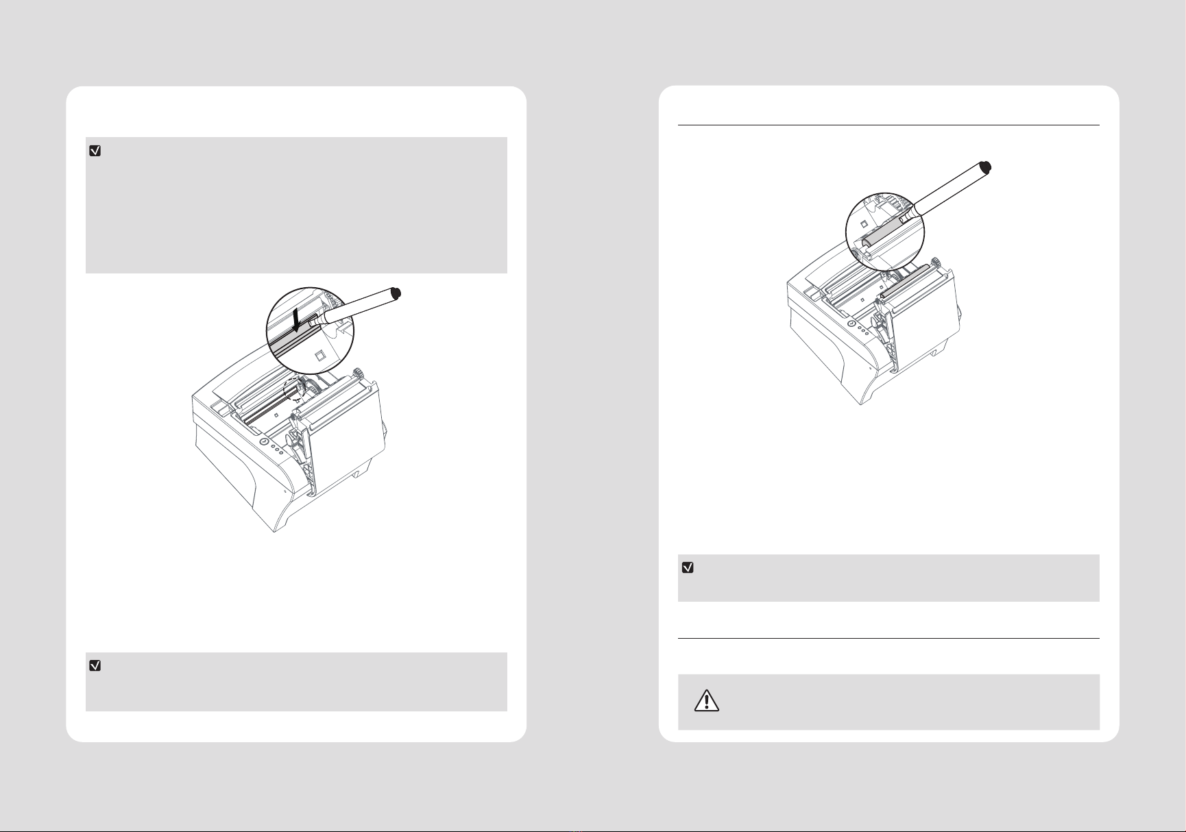
10. Printer Cleaning
If the interior of the printer is dusty, printing quality can be lowered.
In this case, follow the instructions below to clean the printer.
NOTE
1 Make sure to turn the printer power o prior to cleaning
2 Regarding print head cleaning, as the print head is very hot during printing, turn o the
printer power and wait approximately 10 minute before start.
3 When cleaning the print head, take care not to touch the heated part of the print head. The
print head subject to be damaged by static electricity.
4 Take care not to allow the print head to become scratched and /or damaged in any way.
1 Use an applicator swab moistened with an alcohol solution to clean the print head and
remove any dusts.
2 Once the cleaning is completed, insert paper roll into the printer few minutes later and close
the printer cover.
3 In case of using sticky paper, it is recommended to clean it at least once a week or
once after printing on 30 rolls.
Preventing Overheating
To prevent the motor from overheating, continuous operation of the printer should be 1.5 m
or less in print length. Set the pause time for 30 seconds or more than it.
24
23 24
23
Interface Standard USB(B type)
Option Serial(RS-232C), Parallel(IEEE1284),
Ethernet, Wi-Fi(802.11 a/b/g/n),
Bluetooth Ver2.1(Movon,iOS)
Bluetooth Ver 4.2(Movon,iOS)
Cash drawer 2 circuits(24V, 1A Max.)
Reliability MCBF 60 million lines
TPH Life 160Km / Linerless - 100km
Cutter Type Guillotine
Life TE202Ⅱ- 1,800,000 cuts
TE203 - 1,500,000 cuts
Linerless - 1,000,000 cuts
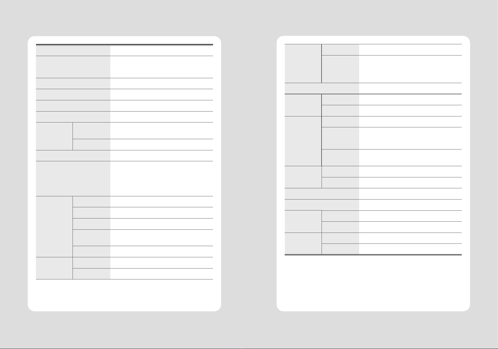
Paper
Thickness 0.06 ~ 0.09mm
Power AC 100 ~ 240Vac 50/60 Hz
DC 24Vdc / 1.75A
Size 1562 × 204 × 150 [W x D x H (mm)]
Weight 1.7kg
Temperature Operation 0 ~ 45℃ (Linerless : 0 ~ 30℃)
Storage -20 ~ 60℃
Humidity Operation 35 ~ 80%
Storage 10 ~ 90%
Printing Method Direct Thermal
Printing Speed TE202Ⅱ- Max. 220 mm/sec
TE203 - Max. 300 mm/sec
Linerless - Max. 160mm/sec
Resolution 180 DPI / 203 DPI (Optional)
Dot Pitch
0.141mm x 0.141mm / 0.125mm x 0.125mm
Printing Width
Max. 72mm / 80mm
Number of print columns
Font A - 42 columns / Font B - 56 columns
Barcode 1D EAN-8, EAN-13, Code 39, Code 93, Code 128,
ITF, UPC-A, UPC-E, Codabar
2D PDF 417, QR code, DATA MATRIX
Emulation ESC/POS Command compatible
Driver Windows Driver(XP ~, Server2003 ~),
Windows CE & Mobile Driver(CE 4.2 ~, Mobile
5.0 ~), Linux Driver, Mac Driver, OPOS Driver,
JavaPOS Driver, iOS SDK, Android(6.0 ~) SDK,
Windows SDK, Windows CE SDK Linux SDK
Paper Paper type Thermal paper / Linerless (Optional)
Width 50 ~ 82.5
Thickness 0.06 ~ 0.09mm
Roll Max
Diameter Max. 80mm
Roll Core 12.5mm ± 0.5mm
Sensor Standard Paper End, Paper Low, Cover Open
Option Black Mark
12 Specications

26
25 26
25
No. Command Function REMARKS
40 ESC t Select character code table
41 ESC { Turn upside-down printing mode on/off
42 FS p Print NV bit image
43 FS q Define NV bit image
44 GS ! Select character size
45 GS $ Set absolute vertical print position in page mode
46 GS * Define downloaded bit image
47 GS / Print downloaded bit image
48 GS B Turn white/black reverse printing mode on/off
49 GS H Select printing position of HRI characters
50 GS I Transmit printer ID
51 GS L Set left margin
52 GS P Set horizontal and vertical motion units
53 GS V Select cut mode and cut paper
54 GS W Set printing area width
55 GS \ Set relative vertical print position in page mode
56 GS a Enable/disable Automatic Status Back(ASB)
57 GS f Select font for HRI characters
58 GS h Set bar code height
59 GS k Print bar code
60 GS r Transmit status
61 GS v 0 Print raster bit image
62 GS w Set bar code width
< Add >
1 ESC i Full cut
2 ESC m Partial cut
3 FS ! Set print mode(s) for Kanji characters
4 FS & Select Kanji character mode
5 FS - Turn underline mode on/off for Kanji character
6 FS . Cancel Kanji character mode
7 FS 2 c1 d1…dk Define user-defined Kanji characters
8 FS C Select Kanji character code system
9 FS S 1 2 Set Kanji character spacing
10 FS W Turn quadruple-size mode on/off for Kanji character
No. Command Function REMARKS
1 HT Horizontal tab
2 LF Print and line feed
3 CR Print and carriage return
4 FF Print and return to standard mode(in page mode)
5 CAN Cancel print data in page mode
6 DLE EOT Real-time status transmission
7 DLE ENQ Real-time request to printer
8 DLE DC4 Generate pulse at real-time
9 ESC FF Print data in page mode
10 ESC SP Set right-side character spacing
11 ESC ! Select print mode(s)
12 ESC $ Set absolute print position
13 ESC % Select/cancel user-dened character set
14 ESC & Dene user-dened characters
15 ESC * Set bit-image mode
16 ESC - Turn underline mode on/o
17 ESC 2 Select default line spacing
18 ESC 3 Set line spacing
19 ESC = Select peripheral device
20 ESC ? Cancel user-dened characters
21 ESC @ Initialize printer
22 ESC D Set horizontal tab positions
23 ESC E Turn emphasized mode on/o
24 ESC G Turn double-strike mode on/o
25 ESC J Print and feed paper using minimum units
26 ESC L Select page mode
27 ESC M Select character font
28 ESC R Select an international character set
29 ESC S Select standard mode
30 ESC T Select print direction in page mode
31 ESC V Turn 90° clockwise rotation mode on/o
32 ESC W Set printing area in page mode
33 ESC \Set relative print position
34 ESC a Select justication
35 ESC c 3 Select paper sensor(s) to output paper-end
signals
36 ESC c 4 Select paper sensor(s) to stop printing
37 ESC c 5 Enable/disable panel buttons
38 ESC d Print and feed paper n lines
39 ESC p General pulse
13. Command List
28
27 28
27
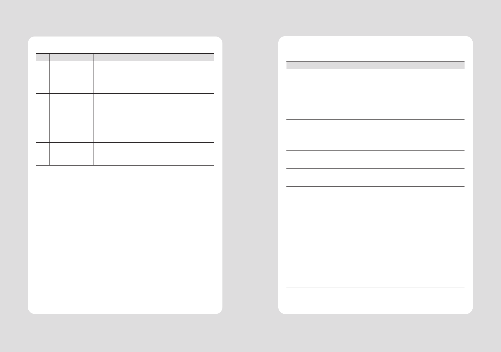
15. S/W
We provides SDK, Driver, etc. as follows to respond to various S/W usage environments.
You can download this S/W from the homepage.
No. Name Description
1Windows Driver
This is an install program used to print a POS printer in Windows OS.
2 Linux Driver
This is the Cups Driver used to print a Thermal printer in the Linux
environment.
3 OPOS Driver
This is a driver that controls POS printers using the OPOS stan-
dard.
It can be used after initial setting(POS Printer&Cash Drawer) us-
ing the setting tool.
4 JavaPOS Driver The JavaPOS driver is an interface standard for POS software
written in Java.
5Mac Driver This is the Cups Driver used to print a Thermal printer in the Mac
OS environment.
6
Android Plugin
(Sewoo Print
Service Plugin)
This is a print service plug-in that allows you to print documents,
images, and web pages without installing additional apps.
7Windows SDK
This is library for communication and data output with Thermal
printer in Windows OS.
Can be used through direct communication and driver.
8Android SDK This is library for communication and data output with Thermal
printers in Android OS.
9iOS SDK This is library for communication and data output with Thermal
printers in iOS.
10 Linux SDK This is library for communication and data output with Thermal
printers in Linux.
The following utilities and concerned manual can be found on the CD or homepage.
No. Name Description
1Memory Saver
This is a utility that allows you to set printers by
interface.
Detailed settings such as Wi-Fi, Ethernet, and COM ports can be
congured.
2 NV Logo Upload
With NV Logo Upload running on Windows OS, you can upload and
remove the bmp le as Logo in the printer’s ash memory, and print
test is possible.
3 Download Tool
(F/W)
Printer F/W and Font Download are available, and BT, Wi-Fi mod-
ule F/W Download is supported as an option.
4 Android Utility
(Sewoo M_Utility)
It is a utility app that prints text, barcodes, images, etc. through
Bluetooth and Wi-Fi communication, and able to printer settings.
14. Utilities
Table of contents
Other SEWOO Printer manuals

SEWOO
SEWOO SLK-D10 User manual

SEWOO
SEWOO SLK-T12EB User manual

SEWOO
SEWOO LK-T41 User manual

SEWOO
SEWOO LK-P300 User manual

SEWOO
SEWOO LK-P41B User manual

SEWOO
SEWOO STL202II User manual

SEWOO
SEWOO LK-P43 User manual

SEWOO
SEWOO SLK-TL12X Series User manual

SEWOO
SEWOO LK-T200 User manual

SEWOO
SEWOO SLK-T42 User manual

SEWOO
SEWOO SLK-TL100 User manual

SEWOO
SEWOO LK-P11B User manual

SEWOO
SEWOO WTP-150 User manual

SEWOO
SEWOO SLK-TS400 User manual

SEWOO
SEWOO SLK-TE25 User manual

SEWOO
SEWOO SLK-TL100 User manual

SEWOO
SEWOO LK-P11 Installation instructions

SEWOO
SEWOO LK-P12B User manual

SEWOO
SEWOO LK-P30W User manual

SEWOO
SEWOO LK-P30IIW User manual


