MAHLE AFC-9 User manual

MAHLE AFC-9 &
CFC-16
EN
Operation Manual
Container Crusher

en
|
2
|
AFC
-
9/CFC
-
16
EVERY PERSON WHO OPERATES THIS
EQUIPMENT NEEDS TO KNOW AND
UNDERSTAND ALL OF THE INFORMATION IN
THIS MANUAL – FAILURE TO DO SO COULD
RESULT IN SERIOUS INJURY OR DEATH.
READ THIS MANUAL
CAREFULLY AND
RETAIN FOR YOUR
RECORDS

AFC
-
9/CFC
-
16
|
3
|
en
Contents
Contents
1. Safety Regulat ons ................................................ 4
1.1 Warnings ....................................................... 4
1.2 Safety instructions for transporting unit ........ 4
2. Foreword ................................................................ 5
2.1 From the manufacturer ................................. 5
3. Symbols Use .......................................................... 5
3.1 Signal wor s ................................................. 5
4. Respons b l t es ..................................................... 6
4.1 Receiving inspection ..................................... 6
4.2 Owner an /or operator responsibilities ......... 6
5. Spec f cat ons ........................................................ 6
5.1 AFC-9 ........................................................... 6
5.2 CFC-16 ......................................................... 6
6. Product Descr pt on .............................................. 7
6.1 Component i entification .............................. 7
6.2 Features ........................................................ 7
7. Installat on ............................................................. 8
8. Operat on ............................................................... 9
8.1 Operation of the container crusher................ 9
8.2 Door han le operation .................................. 9
9. Ma ntenance and Inspect on .............................. 10
9.1 Inspection ................................................... 10
9.2 Maintenance instructions ............................ 10
9.3 Control valve actuation a justment ............. 10
10. Troubleshoot ng .................................................. 11
11. Ma ntenance Chart .............................................. 12
12. Notes .................................................................... 14

en
|
4
|
AFC
-
9/CFC
-
16
Safety Regulat ons
. Safety Regulations
. Warnings
To avoi serious injury or eath, rea this manual
carefully before operating this unit. Call the manufacturer
using the contact information printe on the back cover
of this manual if you have any questions. Failure to
un erstan an obey safety instructions may result in
unsafe or improper use of this pro uct.
The owner / manager must keep th s manual for
future reference, an make sure the warning labels
on the pro uct are legible an intact at all times.
Replacement labels an manuals are available from
the manufacturer. Call the manufacturer using the
contact information on the back cover of this manual
if you have any questions.
The un t s requ red to be anchor bolted to a level
concrete floor, for safe operat on. It is
recommen e to anchor the machine to the floor with
four 3/8 or 1/2 in. iameter anchor bolts.
Th s un t s recommended for crush ng sp n-on o l
f lters, cartr dge o l f lters w th paper elements,
and empty pa nt cans up to 1 gallon n s ze. Do not
crush aerosol cans, cylin ers of compresse gas, fuel
filters, or containers of flammable liqui s or solvents.
Crushing plastic containers is not recommen e .
Do not mod fy th s un t or alter the operat on n any
way to c rcumvent the nterlock ng door
mechan sm. Mo ifications to the machine will voi all
warranties expresse or implie .
Do not smoke when operat ng th s un t an o not
operate this unit when someone else in the vicinity is
smoking.
Wear safety glasses and gloves when operat ng
the un t an han ling the crushe oil filters an paint
cans.
Never hold the f lter by the top when loa ing an
unloa ing. Always hol the filter by the si es with the
gasket en own.
Do not use th s un t to perform any operat ons
other than to crush o l f lters or empty pa nt cans.
This unit is for crushing spin-on oil filters, cartri ge oil
filters with paper elements, an empty paint cans up
to 1 gallon in size. Paint from full or partially full cans
can soli ify an clog the holes in the catch basin.
Clean up any sp lled o l mmed ately so it will not
cause a slipping hazar .
Do not stack o l f lters ns de the crush ng
chamber.
.2 Safety instructions for transporting unit
Failure to un erstan an obey safety instructions
may result in unsafe or improper use of this pro uct.
Failure to un erstan an obey this warning may
result in injury an /or property amage.
The crushing mo ule is very heavy an it is
recommen e to use a shop crane capable of
han ling the loa or lift truck to perform the lifting. Do
not move the unit with the crushing mo ule in the
raise position. Always lower the crushing mo ule to
its shipping position. The unit is top heavy an can tip
over if the crushing mo ule is raise an the unit is
not anchore to the floor.

AFC
-
9/CFC
-
16
|
5
|
en
Foreword
2. Foreword
2. From the manufacturer
Thank you for your purchase. To complement the
offering of A/C, flui an nitrogen service equipment,
MAHLE Service Solutions has partnere with Gray
Manufacturing to provi e the highest quality hy raulic
an pneumatic equipment available for the professional
service technician. This equipment a heres to high
stan ar s promise in the MAHLE guarantee inclu ing
the assurance of innovation an reliability that comes
with the Gray Manufacturing name. Please contact
MAHLE Service Solutions’ customer service at (800)
comments or questions.
3. Symbols Use
3. Signal words
Signal wor s call attention to a safety message or
messages, or a property amage message or messages,
an esignate a egree or level of hazar seriousness.
Signal wor s use in this manual inclu e:
Keyword Probab l ty of
occurrence
Sever ty of danger f
nstruct ons not observed
DANGER
Immediate
impen ing danger
Death
or
severe
injury.
WARNING Possible
impen ing
danger
Death
or
severe
injury
CAUTION
Possible
dangerous
situation
Minor
injury
NOTICE
Possible
damage to
property
Possible property
damage

en
|
6
|
AFC
-
9/CFC
-
16
Respons b l t es
4. Responsibilities
4. Receiving inspection
Before attempting to operate this equipment, thoroughly
rea an un erstan this manual. Completely remove all
tape an packaging. Inspect the equipment imme iately
upon elivery. If shipping amage is evi ent, inform the
elivering carrier imme iately an contact the
manufacturer using the contact information on the back
cover of this manual.
4.2 Owner and/or operator responsibilities
The owner of this equipment must rea these
instructions an maintain them for future reference an
for instructing any other users of the equipment. The
owner is responsible for keeping all warning labels an
instruction manuals legible an intact. Replacement
labels an literature are available from the manufacturer.
The owner must never authorize or allow anyone to use
this equipment until the operator has rea an
un erstoo the information in this manual an on the
accompanying labeling on the equipment itself.
If this equipment is being use in an occupational setting
(or workplace), the employer shoul ensure that all
personnel working with an aroun the equipment know
of the risks associate with its use. Personnel involve in
the use an operation of this equipment shall be careful,
competent, traine , an qualifie in the safe operation of
the equipment an its proper use when servicing motor
vehicles an their components. Safety information
provi e with this equipment shoul be emphasize by
the employer an un erstoo by each employee. The
employer must make this manual available to all
personnel using this equipment an all personnel must
rea an un erstan the contents of this manual. If the
operator is not fluent in English, the manufacturer’s
instructions an warnings shall be rea to an iscusse
with the operator in the operator’s native language by
the employer, making sure that the operator
comprehen s its contents an observes the proper
proce ures for use of this equipment.
5. Specifications
5. AFC-9
Model AFC-9 US un ts Metr c un ts
Height 77.125 in 195.9 cm
Wi th 20.5 in 52.1 cm
Depth 16.75 in 42.6 cm
Weight 242 lb 109.8 kg
Height (Crushing chamber) 9 in 22.9 cm
Wi th (Crushing chamber) 8 in 20.3 cm
Depth (Crushing chamber) 8 in 20.3 cm
Air Inlet ¼ female NPT ¼ female NPT
Air Pressure 100-200 PSI 6.9-13.8 Bar
Catch Basin Connection ¾ female NPT ¾ female NPT
5.2 CFC- 6
Model CFC-16 US un ts Metr c un ts
Height 85.5 in 217.2 cm
Wi th 20.5 in 52.1 cm
Depth 16.75 in 42.6 cm
Weight 282 lb 127.9 kg
Height (Crushing chamber) 16.25 in 41.3 cm
Wi th (Crushing chamber) 10 in 25.4 cm
Depth (Crushing chamber) 8 in 20.3 cm
Air Inlet ¼ female NPT ¼ female NPT
Air Pressure 100-200 PSI 6.9-13.8 Bar
Catch Basin Connection ¾ female NPT ¾ female NPT

AFC
-
9/CFC
-
16
|
7
|
en
Product Descr pt on
6. Product Description
6. Component identification
Fig. 1: Front view
1Catch basin
2Crushing chamber
3Door
4Ram & ram cylinder
5Door handle
6Control valve & air inlet
7Catch basin outlet
8tand
6.2 Features
Pneumat c Powered Ram: Pneumatic power gives you
the a vantages of long life, low maintenance, an quick
crushing action. Also no electrical connections are
require eliminating the electrical hazar an the
problems of irty an /or faulty connections.
Interlock ng Door:
The oor interlock restrains the oor
from opening until the ram is fully raise .
Conven ent Operat on:
::
: One han is require to close
the oor an latch it. After the oor is latche , the
crushing chamber is completely enclose to prevent
injuries an to prevent oil splatter.
Versat le Installat on: The stan is stan ar
with the
unit, not optional as with many competitors’ equipment.
When crushing oil filters, the catch basin can be
connecte to the bottom or either si e to a variety of
waste oil containers. The unit can be place over a
workbench by placing the stan post behin the
workbench.
Large Crush ng Chamber: Automotive spin-on filters
an up to 1-gallon paint cans will fit in the crushing
chamber.

en
|
8
|
AFC
-
9/CFC
-
16
Insta
llat on
7. Installation
1. Locate a suitable place to install the unit. This unit must
be installe in oors on a level surface. The unit is
require to be anchor bolte to a concrete floor, for safe
operation.
2. Position the crusher in the esire location in your shop.
Mark the floor for the anchor bolt location to match the
holes in the base of the stan . Four 3/8 or 1/2 inch
iameter anchor bolts are recommen e to install the
unit. Install the anchor bolts accor ing to the
manufacturer’s instructions. Secure the unit to the floor
with the anchor bolts.
3. The unit is shippe with the crushing mo ule fastene
to the stan in a lowere position.
CAUTION! The crushing mo ule is very heavy an it is
recommen e to use a shop crane capable of han ling
the loa or a lift truck to perform the lifting. Unbolt the
crushing mo ule from the post. Note: the number of
bolts will epen on the mo el. Do not remove the 5/16
inch screw from the top of the post, if equippe . Raise
the crushing mo ule from the shipping position to the
working position. Align the mounting holes on the
crushing mo ule with the holes in the stan post an
insert the bolts provi e . Secure with the nuts on the
bolts.
4. Connect the catch basin to the appropriate waste oil
container as require by national, state, or local
regulations. The catch basin connection is a 3/4 female
NPT fitting locate on the bottom or on the si e. If the
opposite si e connection is esire , simply remove the
catch basin an install with the connection on the
esire si e. The unit may be connecte using a 3/4
male NPT fitting an pipe to a remote waste oil tank.
Another option is to connect the catch basin to a rum.
Use a 3/4 pipe close nipple, a 1 in. I.D. oil resistant hose
an a hose clamp to connect the hose to the catch
basin. Install the hose in the bung of the rum an cut
the length of the hose so it will fit in the rum 2 to 4 in.
The installation must provi e for the easy removal of the
catch basin as slu ge an semi-soli resi ue from oil
filters may accumulate. The catch basin requires
perio ic cleaning to remove soli resi ues. All such
resi ues must be transferre to an acceptable
container.
5. If the unit is to be use solely for crushing empty paint
cans, the catch basin oes not nee to be connecte to
any container. However, a rip pan shoul be place
beneath it or the pipe rain fittings shoul be plugge .
The installation of the unit shoul provi e for easy
removal of the catch basin to remove ina vertent spills
an foreign material, which may accumulate in the catch
basin.
6. Connect the air supply to the air inlet. The inlet
connection is 1/4 female NPT. The unit is now rea y for
use. Recommen e operating air pressure is 100 psi
minimum for most paint cans an car an light truck
filters, 120-PSI minimum for heavy truck filters.
Maximum recommen e air pressure is 200 psi.
7. If for any reason the unit oes not operate properly after
reviewing the steps above consult the Troubleshooting
section in this Owner’s Manual or contact the
manufacturer using the contact information printe on
the back cover of this manual for further instructions an
assistance. Please have the mo el number an serial
number of your crushing equipment available. The serial
number is permanently stampe on a metal tag locate
above the oor.

AFC
-
9/CFC
-
16
|
9
|
en
Operat on
8. Operation
8. Operation of the container crusher
1. Place empty paint can with the li remove or oil filter
with the open en own in the center of the crushing
chamber.
2. Close oor an turn oor han le clockwise
approximately 180 egrees. You may walk away to
perform other tasks. Upon returning, the filter or paint
can will be crushe . If you want to crush containers in
succession, listen for air to stop flowing (up to 45
secon s). Some noise an vibration usually
accompany the crushing process.
3. To remove the crushe paint can or filter, turn the
oor han le counterclockwise an air will exhaust
from the ram cylin er. The oor will not open until the
ram is fully raise (approximately 10 secon s). Open
the oor an remove the crushe , empty paint can or
oil filter.
4. Note: A filter may be crushe for exten e perio s of
time. The unit can be left un er pressure until the next
filter or can is rea y for crushing. The catch basin
outlet can become clogge with slu ge an semisoli
waste from filters. It is necessary to remove the catch
basin an clean it perio ically. Deposit soli resi ue in
acceptable containers. The oil level in the catch basin
can be viewe through the opening beneath the oor
when the oor is close . You may crush several filters
at one time if they are all of similar height an you
have a equate air pressure.
CAUTION: Crushing multiple filters of ifferent
heights or materials can amage the crushing
mo ule. Always have the filters arrange so that they
o not cause the ram to loa unevenly.
8.2 Door handle operation
Door close an han le full clockwise, oor is latche
an ram exten s (Fig. 2).
Fig. 2: Turn handle full clockwise to crush cans
Door close an han le turne 90 egrees counter-
clockwise, air exhausts, ram retracts an oor remains
close (Fig. 3).
Fig. 3: Turn handle 90 deg. counterclockwise to retract ram
Han le turne fully counter-clockwise, air exhausts an
ram retracts, oor will open when ram is fully retracte
(Fig. 4).
Fig. 4: Turn fully counterclockwise to retract ram and o en door

en
|
10
|
AFC
-
9/CFC
-
16
Ma ntenance and Inspect on
9. Maintenance and Inspection
WARNING - The equipment must be inspecte
accor ing to the requirements of this section. Failure
to properly inspect the equipment coul lea to
severe injury or eath. The equipment must be
remove from service an inspecte imme iately if it
is subjecte to an abnormal loa or a shock loa . If
any irregularities or problems are etecte uring an
inspection, the equipment must be remove from
service imme iately an repaire . Contact the
manufacturer at the numbers an a ress printe on
the back cover of this manual.
9. Inspection
The owner must inspect, or appoint a knowle geable
person to inspect the unit for signs of corrosion an / or
excessive wear. Visual inspection shoul be ma e
before each use of the unit, checking for abnormal
con itions. Regular inspections shoul be ma e weekly
for aily use an monthly for intermittent use. Each unit
must be inspecte imme iately if subjecte to an
abnormal loa or shock. Any unit which appears to be
amage in any way, is foun to be ba ly worn, or
operates abnormally shall be remove from service until
necessary repairs are ma e.
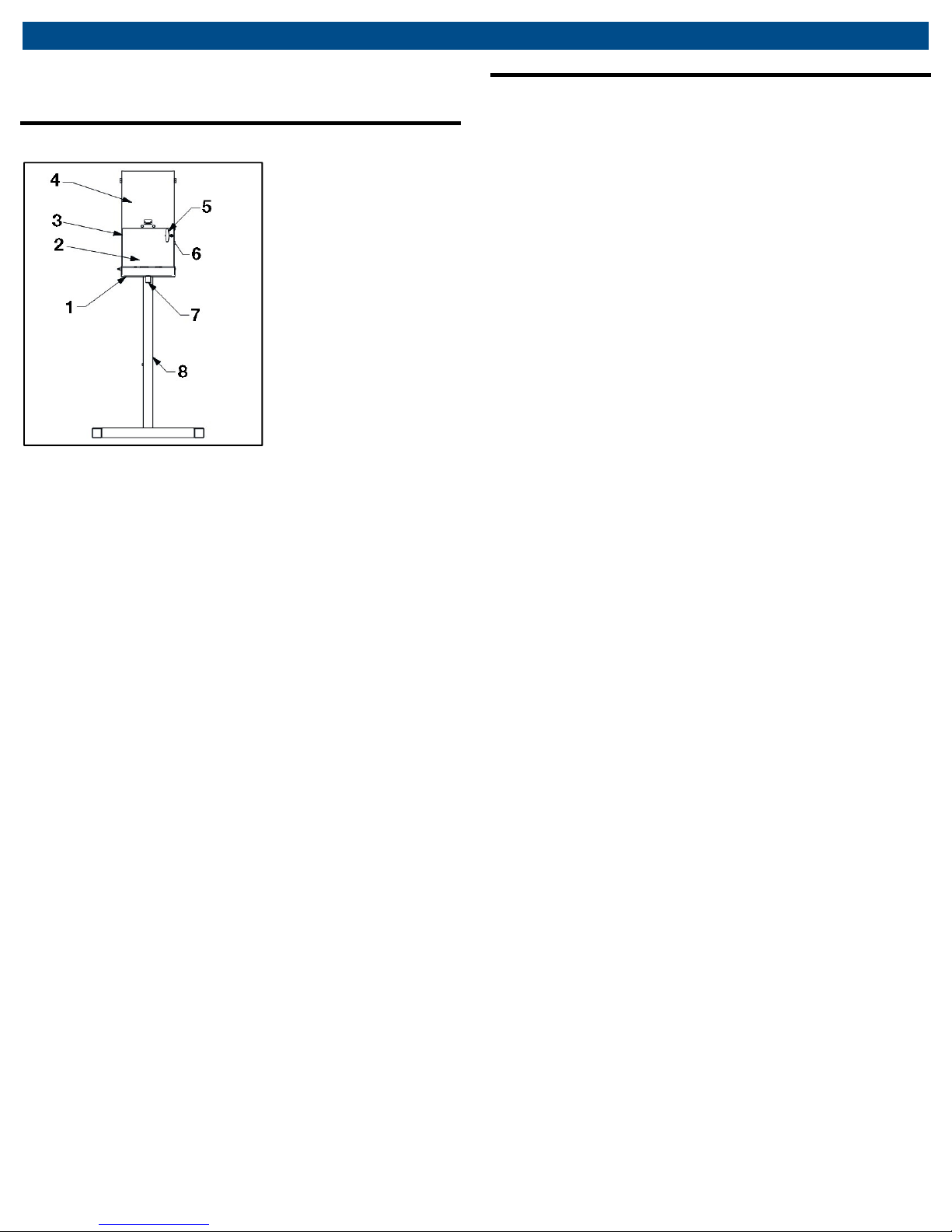
Inspect the oor for closure an oor han le latching
operation. The oor shoul close easily an the oor
han le shoul loosely latch with a 90- egree rotation
of the oor han le. Further 90- egree rotation of the
han le shoul clamp the oor shut an actuate the
control valve. There shoul be the soun of air
flowing for up to 45 secon s until the ram is fully
lowere an the air pressure in the ram cylin er
equalizes with the air supply.
After the air stops flowing, check the unit for
excessive leaks. An excessive leak is a leak which
can be hear an which egra es the performance
of the unit. Minor leaks o not a versely affect the
operation of the unit.
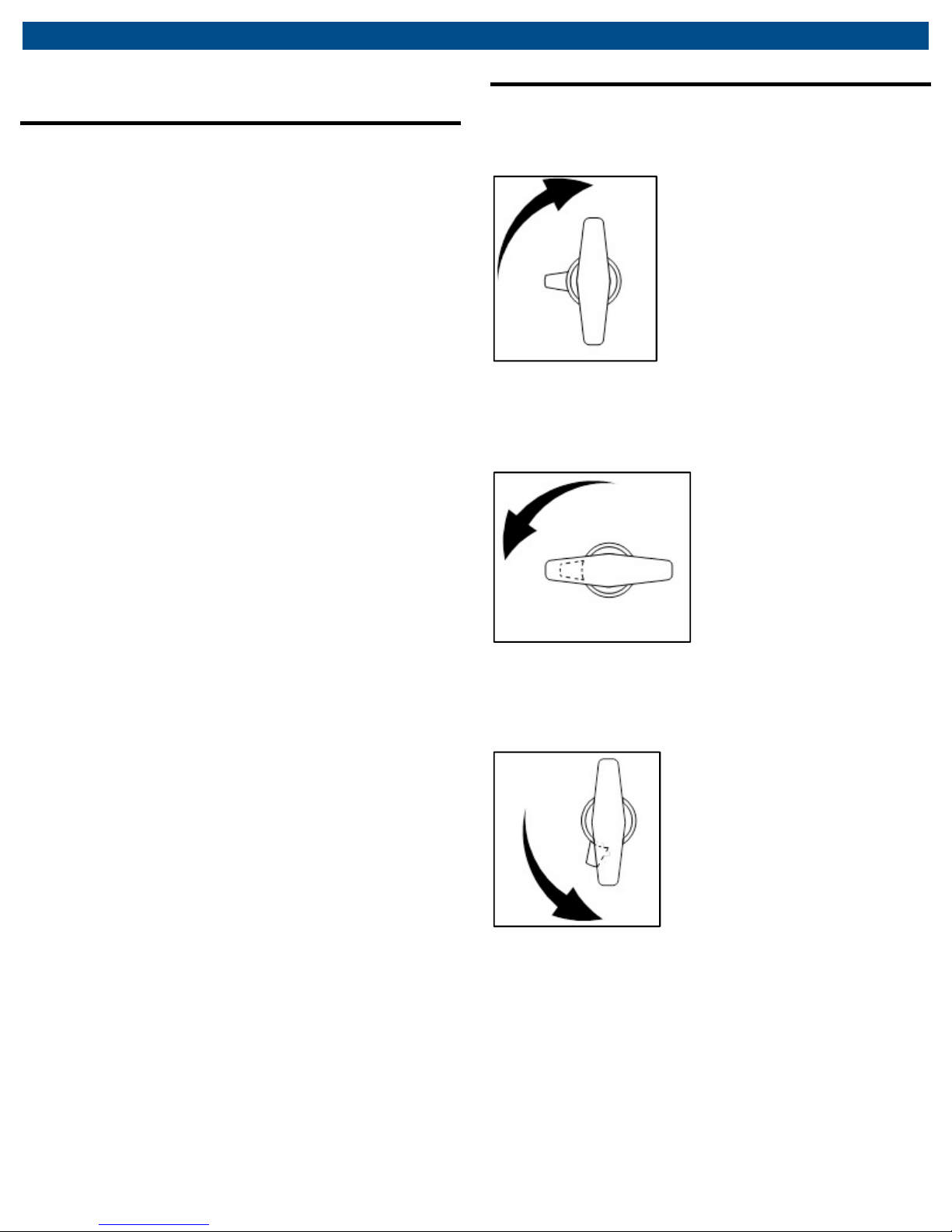
Unlatch the oor an the air shoul exhaust from the
ram cylin er. The oor shoul not open until the ram
has returne to its fully raise position
(approximately 10 secon s).
Inspect crushing chamber for amage or worn parts.
If any irregularities or problems are etecte uring
an inspection, the unit must be remove from service
imme iately an repaire . Contact the manufacturer
using the contact information on the back cover of
this manual.
9.2 Maintenance instructions
WARNING - All inspection an maintenance proce ures
must be performe after the equipment has been remove
from service. Failure to o this may result in personal injury
an /or property amage.
All warning an capacity labels shoul be rea able
an complete. Wash external surfaces of jack, labels,
an ecals with a mil soap solution.
Lubricate all rotating an sli ing portions of the jack
monthly.
9.3 Control valve actuation adjustment
Note: The setscrew on the oor that actuates the
control valve an the pawl on the oor han le latch
are a juste at the factory an shoul never nee
a justment.
1. Make sure the two screws securing the control valve
on the right han si e of the unit are tight. Make sure
the two screws securing the han le latch to the oor
are tight an the two jam nuts securing the latch pawl
to the stem are tight.
2. Loosen the jam nut securing the set screw on the
oor an back the setscrew out. Close oor an turn
oor han le fully clockwise to soli ly latch the oor.
3. Using a hex wrench, slowly tighten the setscrew until
the top platen lowers an there is no air leakage
etecte aroun the spool of the control valve.
Tighten the setscrew 1/2 turn further an secure the
setscrew with the jam nut.
4. Rotate the latch han le 1/4 turn counterclockwise.
The air shoul exhaust an the ram shoul retract, but
the pawl shoul remain loosely engage with the oor
close .
5. Rotate the latch fully counterclockwise an the oor
shoul open. Repeat steps 2 through 5 if the oor
oes not operate correctly.

AFC
-
9/CFC
-
16
|
11
|
en
Troubleshoot ng
0. Troubleshooting
This section is a list of potential problems an
solutions. If the solution liste fails to correct the
problem, call the manufacturer at the numbers an
a ress printe on the back cover of this manual.
Please have the mo el number, an serial number of
your jack available. The serial number is permanently
stampe on a metal tag locate
above the oor or on
the shrou at the top
.
Problem Cause/Solut on
Ram oes not actuate
•Not connecte to air supply. Connect unit
to a equate air supply (see Installation
instructions section of manual).
•Setscrew on oor is not properly actuating
the control valve. A just setscrew (see
Control Valve Actuation A justment
section).
Ina equate crushing
action
•Air pressure too low. 100 psi will
a equately crush most car an light truck
filters. Heavy truck filters require a
minimum of 120 psi.
•Some bran s or mo els of oil filters are
stronger than other bran s an therefore
will not crush as flat.
•Excess air leakage. Locate source of
leak(s) an repair.
•Crushing too many filters at one time or
there is too big of height ifference in the
filters you are crushing at one time. Crush
filters in ivi ually.
Oil is running over the
catch basin
•Make sure vehicle is in neutral an baking
brake is isengage . Always chock wheels
on opposite en prior to lifting.

en
|
12
|
AFC
-
9/CFC
-
16
Ma ntenance Chart
. Maintenance Chart
Act on Date Deta ls Person
respons ble
Receiving inspection

AFC
-
9/CFC
-
16
|
13
|
en
Ma ntenance Chart
Act on Date Deta ls Person
respons ble

en
|
14
|
AFC
-
9/CFC
-
16
Notes
2. Notes

AFC
-
9/CFC
-
16
|
15
|
en
Notes

en
|
16
|
TSL
-
50
670
-
90747
MAHLE Aftermarket Inc.
10 Innovation Drive
York, PA 17402 U.S.A.
Phone: (800) 468-2321
Fax: (717) 755-8304
E-mail: tec[email protected]hle.com
www.servicesolutions.mahle.com
This manual suits for next models
1
Table of contents