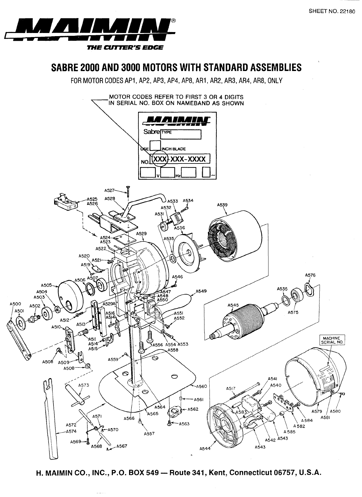
maimin SABRE 3000 Datasheet

BOOK
NO.
22118
Straight
Knife
Cutting Machine
with
Flexi-band Sharpener
(Mode/A)
SABRE
30000
SABRE
20000
Instruction
and
Parts
List
IMACHINE
SERIAL NO.
It
2000
H.
MAIMIN CO., INC.
IMPORTANT SAFETY INSTRUCTIONS
Edition 1.5
When
using your cutting machine, basic safety instructions should always be followed including
the following:
This cutting machine is
for
commercial use only.
Read
all instructions before using.
DANGER-To
reduce the risk of electric shock;
1.
Do
not install or store this machine
in
a wet location.
WARNJN
G-
To
reduce the risk ofburns, fire, electric shock, or injury
to
persons:
1.
Use machine only for its intended use as a portable cutting machine.
2.
Turn machine to
"OFF"
(0)
before connecting
or
disconnecting powercord.
3.
Connect this machine to a properly grounded outlet only. See Grounding Instructions.
4.
Always disconnect electrical connector from machine when not using it, before servicing it, or
changing blade.
5.
Do
not leave machine unattended while
it
is
connected to power outlet.
6.
Do
not operate machine with a damaged cord or if machine has been dropped.
Do
not disassemble
take to a qualified serviceman for repairs. Incorrect assembly can cause electric shock when the
machine
is
used.
7.
Keep hands and fingers away from blade and moving parts.
8.
Keep guards in place and
in
working order.
9.
The knife key and other wrenches must be removed from machine before starting motor.
10.
Keep ventilation openings of machine free from dust and lint.
11.
Keep machine clean and blade sharp for best and safest performance.
Save These Instructions
Maimin Technology, 2915 Courtyards Dr., Bldg. B, Norcross, GA 30071 USA
Tel: 770.447.1800,Toll Free USA: 800.243.4645, Fax: 770.447.1070, Email: [email protected]
From the library of: Superior Sewing Machine & Supply LLC

GROUNDING INSTRUCTIONS
This machine must be grounded. In the event
of
malfunction
or
breakdown, grounding provides a
path
of
least resistance
for electric current to reduce the risk
of
electric shock. This machine
is
equipped with a
Ground
Shield surrounding the
Terminal Pins; this GroundShield
is
designed to be used with a Maimin GroundedConnector,
part
number458A
or
458B.
See wiring instructions supplied with the Connector.
DANGER
-Improper
connection
of
the Maimin Connector can result in a risk
of
electric shock. Check with a
qualified electrician
or
serviceman ifthe groundinginstructions are not completely understood
or
if
in doubt as
to
whether
the machine
is
properly grounded.
Do
not modify the Ground Shield provided with this machine.
Use correct wire sizes with the Maimin Grounded Connector.
U.S.A. ONLY: 1 phase: Use AWG16/3 SJ,
SIT
or
SJE
3 phase: Use
AWG
16/4 SJ,
SIT
or
SJE
INTERNATIONAL; 1P+N+: Use 3x
1,
0 mm CEE
(2)
61
3P+
:Use
4 x
1,
0
mm
CEE
(2)
61
I. DESCRIPTION
1.1
GENERAL
Your new Maimin Sabre straight knife machine
is
delivered
ready for operation.
It
is
merely necessary to connect it to an
electrical outlet of the correct voltage, oil it, and then begin
cutting. The straight knife machine can be used for cutting
various types
of
materials from a few ply
to
the full capacity
of the machine. However, for best results, it
is
recommended
thatthe minimum height ofthelaybe nolowerthanthe bottom
ofthe
cuttingblade at its highest position. ThePresserfootLeg
(Key
No.
A403) acts
as
aprotectiveguardfortheoperatorsothat
it should be down at
all
times. The Presserfoot should lie lightly
on top of the lay when cutting in order to prevent the material
from vibrating.
1.2 FLEXIBANDS AVAILABLE
Three
different grits of"FlexiBands" are available for sharp-
ening the blade:
Coarse -Forhard or coarse materials
(Part
1450-
Box of
100)
(Part
1457-
Box of 500)
Medium -For fine woolens, synthetics and cottons
(Part
1451-
Box of
100)
(Part
1458-
Box of500)
Fine
-Forsheer fabrics, very soft materials
(Part
1452-
Box of
100)
(Part
1459-
Box of500)
1.3 BLADES AVAILABLE
The blades come in three grades and in different shapes for
cuttingunusual ordifficult materials. Thethreegradesavailable
are:
ZK -High Speed Steel...Most popular blade as it wears well
retaining its cutting edge for a long time.
BK-
CarbonAlloySteel...Aqualitybladeless durablethanthe
ZK
blade but less costly.
TK-
TreatedHighSpeedSteel...Retainscuttingedgeverywell.
Used only for hard
or
abrasive materials such as fiberglass or
heavy denim as it
is
very expensive.
See back
cover
for
complete
list
of
part
numbers
of
blades
according
to
size, grade, shape, and quantity.
2
II. OPERATION
2.1
UNPACKING A NEW MACHINE
Duringshipment oil may have flowed ontoPulley A303 which
can cause sharpener to traverse slowly. Sharpener cycle time
is
1.5
seconds.
If
longer,oil
is
causingPulley
to
slip.
To
remove
oil, disconnect power, remove BrakeA342, wipe oil from Pulley
and Crank A505. Replace Brake.
2.2
TO
START
Fill oil cups. Attach Connector A525 to Terminal Pins A523.
Move switch A550 from
"off'
to "on" (USA) or
"0"
to
"I"
(International).
Caution: 3 phase motor must turn counter-clockwise when
viewed from rear. (FlexiBand against Blade must rotate from
back to front).
2.3
TO
SHARPEN BLADE (Figure 1)
Machine should be clear of lay and Presserfoot
"A"
should be
down on Baseplate "B". With motor running, move Tripper
Handle
"C"
to
right (facingsharpener) until it latches. Release
it. Sharpener
will
automatically sharpen entire blade. Repeat if
necessary.
Figure 1
From the library of: Superior Sewing Machine & Supply LLC

2.4 TO CUT
Raise Presserfoot A402 above top of lay
by
pressing down on
PresserfootHandleA323andliftingPresserfootLift.ForSqueeze
Trigger, pull Handle
23308
towards machine Handle A549.
Enter lay, and lower Presserfoot to top of lay
by
releasing
Presserfoot Trigger. When making turns
in
lay, it
is
sometimes
advisable to let Presserfoot ride freely on top of lay
by
pushing
downonPresserfootHandle. Whenmachine
is
not
in
use, always
lower Presserfoot to Baseplate. The Presserfoot Leg acts
as
a
safety guard for the blade.
2.5 TO CHANGE FLEXIBANDS (Figures 2 and
3)
a) Disconnect power.
b) Figure
2:
Push Block
"A"
torelease right (upper) FlexiBand
"B".
Remove
FlexiBand from Block and then from
Drive
Pulley"C'
c) Figure
3:
Slip new FlexiBand "B"over Drive Pulley
"C
"and
between Band Plate
"D"
and Blade "E." Push Block
"A"
forward and slide FlexiBand over it. Release Block
"A."
d)
Remove
left
(lower)
FlexiBand,
and
install
new
one
in
same manner.
2.6 TO CHANGE BLADE (Figure
4)
a) Disconnect power and lower Presserfoot Leg.
b) Lay machine on left side.
c) Press and tumThumbwheel
"A"
tomove Blade to its lowest
position.
d)
With
Knife Key
"B"
turn
Nut
"C"
counter
clockwise to
unlock blade.
e)
Raise
Presserfoot
Leg
and
slide Blade
"D"
downwards
and
out.
f)
CleanInserts
"E"
with slot cleaning tool or bottomcorner
ofblade.
g)
Slide new Blade up against Knife Locking Bolt.
h) Holding lower part
of
Blade behind edge, push it firmly up
against Bolt and back against Inserts.
i)
Tighten Nut "C."
Note:
Use
only
genuine
Maimin
Blades
with
"Cut-Out"
and
T-shaped
slot
in
shank
for
optimum
performance
and
safe
operation. 3
Always tighten Knife Locking
Bolt
andNut before running
machine to prevent damage to Crosshead ASJO
and
Gibbs
A513.
Do
not
run sharpener without blade in machine or
sharpener willjam.
2.
7 TO CHANGE BEVEL WIDTH ON BLADE
(Figure
5)
a)
Run
sharpener
to
lowest position,
tum
off motor, discon-
nectpower.
b) Loosen Screw "A."
c) Insert Bevel Adjusting Tool "B" into Washer
"C"
and rotate
Washer
to
increase
or
decrease blade bevel width. Note
arrow
on washer and edge width indicator on Band Plate
Carrier (A374).
d) Tighten Screw
"A."
e) Bevel on opposite side
is
adjusted
in
same manner.
Figure 5
2.8 MAINTENANCE SCHEDULE
a)
Daily: Fill oil cups (A547). Use either Maimin Oil22109 or
quality "30 weight" oil (I.S.O. viscosity grade 220).
b) Weekly:
(l)Sharpener-run
tolowestposition,
tum
offmotor.and
blow out lint and dust with compressed air.
(2)
Motor-
run motor, and point stream ofcompressed
air
into
back ofmotor and side of front housing by fan to
eject lint and dust.
c) Every 500 hours ofoperation:
(1)
Sharpener-Remove
Cap Screw (A367A) from top of
GearCase (A367) and squeeze in a small amount ofGrease
22174 to coat gears.
(2)
Motor-
Remove motorcover and, with compressed air.
blow lint and dust from motor coils and armature.
From the library of: Superior Sewing Machine & Supply LLC

2.9 TO REMOVE SHARPENER FROM MACHINE
(Figure
6)
a)
Run
sharpener
to
lowest
position,
turn
off
motor
and
disconnect power.
b) Figure
6:
DisengageTripperHandle
"A"
byinsertinghandle
of Knife Key
"B"
through hole in lower cover and pressing
upwardsuntilTripperHandlesnapsback
to
its
"off'
position.
c)
Remove
ScrewA390 holding Clamp
Plate
A394 against
Band Plate Guide A393 and remove Guide and Plate.
d) With 3/8" wrench remove 2 Nuts A344 and 2Washers A343
holding Brake A342, and remove Brake.
e)
Remove
Screw
A3J6
holding Shafts
Cover
A315, and lift
off
Cover.
f) Remove3Nuts A328 and1Nut
SlOB
(atlowerleftrearcorner
ofsharpener) which hold Drive Housing A327.
g) Pull sharpener forward gently to remove.
2.10 TO ATTACH SHARPENER TO MACHINE
a) Disconnect power.
b) Wipeoilfrom outerdiameterofCrankA505 andPulleyA303.
c) Place sharpener onto 3 mounting Screws A521 on Front
Housing.
d) Addand tighten3NutsA328and Nut
SlOB
onback of sharpener.
Figure 7
e)
Add
Band Plate Guide A393 and Clamp Plate A394.
f)
HoldGuide against Standard A564 and tightenScrewA390.
g) LowerPresserfootLeg toBaseplate,connectpower,andrun
sharpener to its top position. Disconnect power.
h)
Add
Shafts Cover A315.
i)
Add
Brake A342.
2.11 TO SET POSITION OF BAND PLATE
CARRIER A374 (Figure
7)
a)
Run
sharpener
to
highest
position,
turn
off
motor,
and
disconnect power.
b) Figure7: Measure distance between Cover
"A"
(A361) and
top of
Gear
Case
"B"
(A367). Maximum distance
is
25/32"
(2
em) when Screw A363
is
adjusted properly.
c)
If
distance
is
greater,loosenNutA366 andlowerScrewA363
a few turns. Tighten Nut, run sharpener, and measure again.
d) AexiBandsA386mustnottouchbladeA574whensharpener
is
at top position.
2.12 TO REMOVE MOTOR COVER A579
(Figure 8)
Disconnect Power. Loosen the 3 Screws A580, and slide Motor
Cover off.
Ill. TROUBLE SHOOTING GUIDE
3.1
MACHINE TROUBLE SHOOTING
Symptom
1.
Bottom corner
of
blade breaks.
2.
Motor slow in reaching full speed.
3.
Motor binds at one spot.
4.
Motor becomes hot.
5.
Motor rotates wrong way.
6.
Motor does not start.
7.
Terminal Block and/or Connector
becomes very hot.
8.
Machine does not roll freely on table.
4
Possible Cause
a) Inserts (A558) badly worn.
b) Knife strikes throat plate.
If
cutting hard materials, use
wide slot throat plate.
a) Low voltage
or
wrong voltage.
b) Three phase:
(1) Fuse out on one phase.
(2) Ground wire incorrectly connected to machine.
a) Crosshead (A510) and Gibbs (A513) tight.
b) Standard (A564) not in alignment with Crosshead (A510).
c) Standard (A564) bent.
a) Lint and dust inside Motor Cover (A579).
b) Three phase: one phase not working.
a)
Three
phase: Wiring incorrect. Change any two wires in
Terminal Block (A522)
or
Connector (A525).
a) Connector (A525) not firmly attached to Terminal Pins
(A523).
b) Switch (A550) defective.
c) Starting Switch
or
Relay (A540) and/or Capacitor (A543)
defective.
d) Broken Jumper Wire. (Capacitor to Starting
Switch
or Relay)
a) Inserts in Connector (A525) worn. Change Connector.
b) Terminal Pins (A523) worn.
a) Surface
of
cutting table not smooth.
b) Cushions (A561) in Roller Carriers compressed causing
.Baseplate (A560)
to
drag on table.
·~·
From the library of: Superior Sewing Machine & Supply LLC

(
'
(
(
3.2 SHARPENER TROUBLE SHOOTING
Symptom
1.
No bevel on
one
side ofblade.
2.
Sharpener runs but bands do not rotate.
3.
Sharpener does not run but bands rotate.
4.
Sharpenerdoes not run, bands do not rotate.
5.
Band cut offby blade.
6.
Block (A397) falls off during band changing.
7.
Block (A397) pivots, twisting band.
8.
Sharpener runs slowly.
9.
Sharpener overruns top position.
10.
Sharpener runs continuously.
11.
Sharpener runs only when Tripper Handle
is
held.
12.
Sharpenerjams.
13.
Presserfoot Leg (A403) does not move freely.
14.
Presserfoot Leg does not hold.
15.
Safety not working.
16.
Bands touch blade in top position.
17.
Bevel very wide on both sides
of
blade.
5
Possible Cause
a) Broken Torsion Spring (A382,A388).
b) Band Plates (A381, A387) do not pivot freely.
c)
Bands do not cross due to interference
of
Band Plates
(A381, A387).
a) Square Shaft Gear (A336) broken.
b) Retaining Ring (A338) missing.
c)
Clamp
(A
364) out
of
position.
a) Keeper Plate (A334) loose.
b) Boat (A333) worn.
c) Diamond Shaft (A356) worn.
a) Presserfoot Leg (A403) not down completely.
b) Oil on Crank (A505) and/or Pulley (A303).
c) Retaining Ring (A320) missing.
d) Cluster
Gear
(A332) broken.
a) Band Plate (A387) defective.
a) Retaining Ring (A398) missing.
a) Stud (A383) broken.
a) Oil on Crank (A505) and/or Pulley (A303).
b) Band Plate Guide (A393) too tight against Standard (A564).
c)
Worn Pulley (A303).
d) Dirt in Cartridge (A318).
e) Bent Link (A346).
f)
Worn Push Rod Cam (A314) and/or Tripper (A350).
g)
Add
Grease 22174 to Band Plate Carrier Gears (A374i.
a) Screw (A363) too low.
a)
Screw
(A363)
too low-less than
1"
above Gear
Case
(A36TI.
a) Pin (A348) broken.
b) Worn Push
Rod
Cam (A314) and/orTripper (A350).
a) Sharpener run without knife in machine.
b) Boat (A333) broken.
c) Diamond Shaft (A356) bent.
d) Standard (A564) bent.
e) Nylon Washer (A360A) broken.
a) Sharpener not at top position.
b) Dirt in Leg Guide (A354).
c) Brake (A342) too close to Pulley.
d) Presserfoot Leg (A403) bent.
a) Lock (A330) loose on Shaft (A325).
b) Presserfoot Handle Spring (A322) broken.
c) Teeth worn on Lock (A330).
d) Screw (A324) loose.
a) Leg Guide (A354) broken.
b) Link (A346) bent.
a) Screw (A363) too high.
b) Cams (A515, A516) too high, broken or bent.
a) Worn Band Plates (A387, A381).
b) Band Plate Guide (A393) too tight.
From the library of: Superior Sewing Machine & Supply LLC

A356
Diamond
Shaft
Assembly
Part No. Description
23093D
23093E
23093F
23093K
23093L
23093M
23093R
23093S
23093T
23093U
23093V
23093W
23093X
23093Y
Diamond Shaft 6H
Diamond Shaft 6M
Diamond Shaft 6L
Diamond Shaft 8H
Diamond Shaft
8M
Diamond Shaft 8L
Diamond Shaft
llH
Diamond Shaft 11M
Diamond Shaft
llL
Diamond Shaft 14H
Diamond Shaft 14M
Diamond Shaft 14L
Diamond Shaft 10H
Diamond Shaft 10M
MODEL
A
SHARPENER
6
A403
SQUEEZE
TRIGGER
ASSEMBLY (23309)
23323~
23303
481F
From the library of: Superior Sewing Machine & Supply LLC

PARTSUST
KEY
PART
KEY
PART
NO.
NO.
DESCAIPTION
NO. NO.
UUCRtPllQN
A300
83SN
Nut,
1/4-20
Hex
A361
23244
Cover
""-"
A301
1499D
Vlasher
23303
Cover,
Squeeze
Trigger
Only
A303
23340
Pulley
'INhe
elAn:
mbly
A362
23226
Screw,
6 x l/4SocketHd. Cap(2)
A303A
23341
Pulley'IN'heel
Assemblywi1499D
~hers
A363
23290
Screw,
10
x
1-1/2
Filister
Hd.
A305A
23196
WonnShaft
A364
23212
Clamp
w/23263
A308
839W
W8Sher
.32
X
1/2
X
1132
23263
Screw,
10
x
112Slot
SetFlat
Pt.
A309
23234
R.ebrininj:
RinB
.5100-31
A36.5
824T
Screw,
6 x
3/8
SocketCap(4)
A310
23066
S~
Pin,
7/64x
1/2
A366
S36N
Kepnut,
10-32
Hex
A311
23067
Wonn
A367
23275
Gelll'
Case
with
Bu:shinr;s
A312
23036
Push
Rod
A367A
4365
Geiii
Cue
Ore
BSe
Screw
A313
23267
Spring
Pin,
1116
x
3/S
A36S
23086
Beuin;,
flB111:ed
.:m
x
.377
x
114
A314
23005
Cam
A369
23091
Bearing,
flal1ged
.2.52
x
.377
x
1/2
A314A
402BL
Tapered
Plug
#181
A369A
23091A
Bearing, Left
Driven
Gear
A315
23229E
Shafts
Cove~;
6"
&
8"
A370
23210
Drive
Gear
23229C
Shafts
Cove~;
10"
&
II"
A371
23086
Bearing,
fla111:ed
.:l52
x
.377
x
1/4
23229D
Shafts
Cove~;
14"
A372
23208
Driven
Gea~;
left
A315A
402BL
Tapered
Plug
#lSI
A373
23209
Driven
Gee.~;
rit:ht
A315B
402BJ
Tapered
Plug
#241
A374
23276
Band
Plate
Callier
wJBushinr;s
&
Studs
A316
23261
Washer
.203
x
.500
x
.047
A37.5
23261
Washe
I;
3/16 X l/2 X 3/64
446S
Screwl0-32 x3/4SocketCap
A376
23084
Screw,
10
x 1/JSocket
Hd.
Cap
A317
481FA
Screwl/4x
3/S
x
11116
4 Shoulder(])
A377
23098
Rubber
Tire
(2)
A31S
23192
Cartlldge
wfWonn
& Pulley
A378
23099
Drive
Pulley
(2)
A319
23017
SpriJ.lg
A379
23097
Sc1-ew,
4 x
118
Soc.
Set
Flat
Pt.
(2)
A3JO
23219
R.ebrininj:
RinB
5555-23
A380
23227
R.etainin;
RinB
s1
00-25
(2)
A322
492
T11!:ger
Spri111:
A3Sl
23165
Band
Pia
te,
right
A323
23047
P1-esse1foot
Handle
A382
23110
Spring,
Thrsion,
1ight
A324
490
Sc1-ew;
5116
x
318
Set
A383
23115
Stud,
liS
X
1-1/S
(4)
A325
23049
Shaft
A384
23116
Spring
Pin,
3/32
X 1/4
(2)
A326
23053
Tripper
Handle
A3S5
23117
Spring
(2)
A327
232740
D1ive
Housing
with Busbin;
A3S6
1450
Flexiband,
Coarse-
1
00/box
A327A
510A
Screw;
10
x 1/J
Socket
Set
Cap
1451
Flexiband,
Medium-
I
OOJbox
510B
Nut,
10-32
Hex
1452
Flexiband,
Fine-
1
00/box
A328
23252
Nut,
10-32
Socket
(3)
A3S7
23164
Band
Pia
te,
left
A329
23271
Screw;
8 x
518
Scoket
Hd.
Cap
A388
23109
Spring,
Th1'Sion,
left
A330
23050
Lock
A3S9
23223
Eccenhic Stud
(2)
A332
23189
Cl
usler
Gear
A390
23019
Screw,
6 x
.'i/8
Socket
Cap
23243
Cup(2)
A391
802S
Sc1-ew,
6 x
3116
Pen
Hd.
(2)
'-
A333
J3119A
Boat
w/Y.eepe
r
Plate
:!3120
A391A
402BJ
Thpered
Plug
HJ41
A334
23120
Y.ee
per
Plate
A39J
23225
Washer(J)
A335
23259
Screw;
6x 1/4(2)
A393
23250
Band
Plate
Guide,
6"
A336
J3203
SqUill'!!
Shaft
Gear
2325DA
Band
Plate
Guide,
8"
&
10"
A337
23273
Gear
Block
with
Bushi11gs
23282
Band
Plate
Guide,
11"
&
14"
A338
1277
R.e
brini11g
Ring
5108-50
A394
23249
Clamp
Plate
A339
23251
Sc1-ew,
10
x 3/4
Soc.
Set
Flat
Pt.
A395
23114
Stud, Idler Pullsy(2)
A340
23019
Sc1'!!w6
x 5/8
Socket
Cap
(2)
A396
23293
Plllle:>~
Idle~;
wJBus~
(2)
A341
23091
Sp1il1g
A397
23111
Block{2)
A342
23200
Brake
23280
Block
wfldler
Pulleji
:left
A343
23007
WasheJ;
13/64 x
7/16
x
1132
(2)
23281
Block
wfldler
Pulle)l
rir;ht
A344
510B
Nut,
10-32
Hex
(2)
A398
23288
Retaining
Ring,
5144-12
(2)
A345
23016
R.ebrininj:
Rillg
5144-25
A399
2311J
Screw,
8 x
1/2
But1Dn
Hd.
(2)
A346
232&4
Lillk
Assembly
A400
23316
Lockwashe~;
#4
Split
A346A
23344
W8Sher,
.2.55
X
.468
X
1132
2331&
Sc1-ew,
# 4 x
318
Socket
Hearl
Cap
A348
J332S
T1ippe
r
Pill
wf840D
23319
Lock
Nut,
#4-40
Hex
23011A
T1ippe
r
Pill
On!
y'
A401
23013
Spring
Pin,
3132
x
5116
840D
R.e
brininj:
Ring
A402
23040
Presserlbot, 6",
8",
10",
11",
14"
A349
23013
S
plil'lg
Pin,
3/32
X
5/16
A403
23042B
Presserlbot
Leg
wllifl
&24A-
6"
A350
23190
Tl.ipper
23042D
P1-esse
rl'oot
Leg
wllift
&24A-
8"
A351
23054
Sci'!!W:
6 x
1/8
Socket
Set
Cap
23042H
Presserl'oot
Leg
wllift
&24A-
10"
A353
23258
Screw4x
318
23042F
PI'!!sserl'ootLe~:
wllift
&24A-
11"
A354
23217
Leg
Guide
w/Leg
Keeper
23042G
P1userl'ootLe~:
wllift
&24A-
14"
23325
Leg
Guide
Assy,
Squeeze
T1igger
Only
A404
23013
sf.Ri.s
Pin,
3132
x
SJ16
A355
23122
Scl'!!IO;
6x l/4Button
Hd.
Socket
Cap
(
4)
SQUEEZE
TRIGG
SEMBLY
(23309C)
A356
23093D-Y DiamondS
haft
Assy.
(see
Chart
Pg.
6)
23122
Screw,
6 x 1/4
But1Dn
Hd.
A356A
23286
Sc1'!!w,
10
X
1/2
Button
Hd.
Soc.
Cap
14"
23303
Cover,
Squeeze
Trig~:er
Only
Mac
hines
Only
23307
Spring
A356B
23287
WBSheJ;
Nylon,
14"
l\.1achines
Only
23309
Squeeze
TriggerHI!IIdle
Assembly
A357
23008
Sp!illg
23323
Locknut
10-24
A358
23007
W8SheJ;
13/64X
7/16
X
1132
3090
Br8Ss~ber
A359
23267
Sp1il1g
Pin,
1116
x
3/S
481F
Sc1-ew,
114
x
3JS
Shcul.der
A360
J3211A
SqUill'!!
Shaft,
6" &
8"
223211C
SqUIIl'e
Shaft,
10"
&
11"
23211D
SqUlll-e
Shaft,
14"
A360A
23320
WBSheJ;
Nylon,
S
qUlll-e
Shaft
'-
23321
Screw;
6 x 3/8
Button
Hd.
Socket
Cap
AJwaya
Give
Mactme
8ERIAL
NUMBER
\Yhen
Ordering
Par1s.
Order
By
PART
NUMBER-
Not
Key
Number
7
From the library of: Superior Sewing Machine & Supply LLC

THE
etlfTER'S
EDCE
SABRE
2000
AND
3000
MOTORS
WITH
STANDARD
ASSEMBLIES
FOR
MOTOR
CODES
AP1,
AP2,
AP3,
AP4,
AP8,
AR1,
AR2,
AR3,
AR4,
ARB,
ONLY
MOTOR CODES REFER TO FIRST 3
OR
4 DIGITS
IN
SERIAL NO. BOX ON NAMEBAND AS SHOWN
c!'!!.~.!!'!IIN-
SaD"eiTYPE
I
~
~/
A5721k
A574
~A570
A
56
A568
~A567
SHEET
NO.
22180
H.
MAIMIN CO., INC., P.O.
BOX
549-
Route 341, Kent, Connecticut 06757, U.S.A.
From the library of: Superior Sewing Machine & Supply LLC

PARTS'
LIST
PART NO. PART NO.
KEY SABRE SABRE DESCRIPTION KEY SABRE SABRE DESCRIPTION
NO. 2000 3000 NO. 2000 3000
A500 412A 412A Connecting Rod - H 15282 Armature Assembly, Sabre 3000
412B 412B Connecting Rod - M A546 441S 441S Screw, 6 x
o/,
6 Fillister Hd.
(2)
412C 412C Connecting Rod - L A547 402BD 402BD Oil Cup
A501 413W 413W Bearing Lock 402B 402B Oil Cup Assemblywith Tube
A502 415 415 Crank Pin A548 466G 466G Cover, Switch Box
A503 414 414 Crank Bearing A549 464P 464P Contoured Handle w/Bushing
A504 415N 415N Crank Nut A550 443 443 Switch
A505 413BX 413BX Crank w/413W, 414, 415-H A551 464R 464R Shield
413CX 413CX Crankw/413W, 414, 415-M A552 818S 818S Screw, 6 x
V4
Flat Hd.
413DX 413DX Crankw/413W, 414, 415-L A553 410 410 Screw, 8 x
Y2
Fillister Hd.
(2)
A506 404E 404E Retaining Ring A554 410N 410N Nut
(2)
A507 403 403 Bearing #203 A556 425A 425A
Bolt,%
x
3/.s
Button Hd.
(3)
A508 416 416 Knife Bolt & Nut A557 427S 427S Screw, 10 x
%Flat
Hd. Soc.
(6)
A509 411A 411A T-Siot Lock A558 428B 428B Insertfor
Standard-
8"
A510
411
411
Crosshead w/411 P 428D
4280
Insertfor
Standard-
6"
A511 411P 411P Wrist Pin 428G 428G Insertfor Standard - 1
0"
A512 409A 409A Screw, 8 x 3/4 Fillister Hd.
(6)
428H 428H Insert for
Standard-
11"
A513 409C 409C Gibbs, pair 428M 428M Insert for
Standard-
14"
A514 23226 23226 Screw, 6 x
'14
Socket Hd.
(2)
A559 428T 428T Insert Screw
A515 23151 23151 Cam, Right A560 429C 429C Baseplate with Rollers & Lip
A516 23152 23152 Cam, Left 440L 440L Swivel Baseplate with Rollers & Lip
A517 419U MotorBolt, 8-32 x
4112
Hex Washer A561 436K 436K Rubber Cushion
Hd.(4) A562 436 436 RollerCarrier Assembly
419F MotorBolt, 8-32 x
43/4
HexWasher 440M 440M Swivel RollerAssembly (Rear)
Hd.
(4)
440J
440J Swivel Adaptor Ring
A519 802S 802S Screw, 6 x 3A6 Binding Hd.
(2)
A563 436S 436S Screw, 10 x
%2M
Hd.
A520 402L 402L Oil Guard A564 424BS 424BS Standard -
8"
A521 23230 23230 Screw, 10 x % Flat Pt. Soc. Set
(3)
4240S
4240S
Standard-
6"
A522 405 405 Terminal Block with Pins 424GS 424GS Standard
-10"
A523 406 406 Terminal Pin
(2)
424HS 424HS Standard -
11
"
A524 405PE 405PE Fibre Cover 424MS 424MS Standard
-14"
A525 458B 458B Current Connector A565 430 430 Lip
A526 458K 458K Ground Shield A566 426A 426A Throat
Plate-
6",
8"
A527 408 408 Screw, 8 x 1% Flat Hd. 426B 426B
ThroatPiate-10",
11",
14"
A528 407D 407D Top Handle 426C 426C Throat Plate, Wide
Slot-
6",
8",
1
0"
A529 402AB 402AB Front Housing w/23230
(3)
426E 426E V Throat
Plate-
6",
8"
A529A 402BG 402BG Tapered
Plu~
#7-S 426F 426F VThroat Plate
-10",
11
",
14"
A531
468J 468J Thumbwhee w/Shaft A567 436S 436S Screw, 10 x %2M Hd.
A532 468C 468C Spring A568 431B 431B Shaft, Short
A533
4680
4680
Thumbwheel Support A569 802S 802S Screw, 6 x 3
/,
6 Binding Hd.
468A 468A Thumbwheel Assembly A570 802S 802S Screw, 6 x 3;j6 Binding Hd.
A534 468S 468S Screw, 6 x
%Socket
Hd.
(2)
A571 433A 433A Spring, Lip
A535 497P 497P Support Washer A572 431A 431A Shaft, Long
A536 400K 400K Fan A573 457 457 Knife Key
A539 15260 Shell & Field Assembly, SABRE 2000 A574 Blade (see back cover)
15283 Shell & Field Assembly, SABRE 3000 A575 403 403 Bearing #203
A540 365A Starting Switch, SABRE 2000 A576 15195 15195
Loadi"8
Spri~
365J Starting Switch, SABRE 3000 A579 302QB Motor over, ABRE 2000
A541 15264 15264 Screw, 8-32 x
1'14
Phillips Pan Hd.
(2)
302QM Motor Cover, SABRE 3000
15288 15288
Washer%
x .175 x .035
(2)
A580 23122 23122 Screw, 6 x
'14
Button Hd.
(3)
A542 15266 15266 Screw, 8-32 x
%Phillips
Pan Hd. A581 309F 309F Lockwasher, #6
(3)
A543 15262 15262 Capacitor Clamp A582 483G 483G Terminal Strip
15079 Capacitor
161
mfd -Sabre 2000 A583 15265 15265 Spacer, Starting Switch
(2)
15076 Capacitor 270 mfd
-Sabre
3000 A584 15267 15267 Screw, 8-32 x
%Phillips
Pan Hd.
(2)
A544 15261
15261
Back Housing A585 15268 15268 Spacer, Terminal Strip
(2)
A545 15277 Armature Assembly, Sabre 2000
Always Give Machine SERIAL NUMBER When Ordering Parts.
Order
By
PART
NUMBER-
Not Key Number
H.
MAIMIN
CO.,
INC.
P.O. BOX
549-
ROUTE 341, KENT, CONNECTICUT 06757, U.S.A.
PHONE: (203) 927-4601 FAX: (203) 927-4703
Printed
in
U.S.A. MPS2, 3/0991
From the library of: Superior Sewing Machine & Supply LLC

H.
Maimin Co., Inc. Page 1 2
P.O.
Box
549, Route 341, Kent,
CT
06757
USA
SUPPLEMENT
PARTS
SHEET
FOR
MAIMIN
SABRE
2000
STRAIGHT
KNIFE
MACHINE
ONLY
FOR
SERIAL
NUMBERS
BEGINNING
WITH
AP51,
AP
61,
OR
AP71
AND
ENDING WITH -30123
OR
HIGHER
Part
Number
Key No. 1-Phase 3-Phase Description
A505
A517
A522
A523
A524
A525
A526
A527
A529
A539
A544
A545
A549
A559
A560
A562
A564
A565
A566
A568
A571
A579
A580
A581
A582
413LX
413MX
413NX
413VA
413V8
419U
405AA
406A
405B
458A
458MA
408B
402AF
15348
15349
15227
464S
428V
4298
440R
436F
424DX
4248X
424GX
424HX
424MX
4308
427S
431C
433C
30208
231228
23343
23345
16660
315AS
Crank w/413W, 414, 415-H
Crankw/413W,
414, 415-M
Crank w/413W, 414, 415-L
Screw, % x % Flat Pt. Soc.
Set
Screw, 10 x 3/16 Flat
l?t.
Soc.
Set
Motor Bolt, 8 x
4Yz
(4)
Terminal Block
Terminal Pin (3)
Cover
Connector, 3 Phase
Ground Shield
Screw, 8-32 x 2 Flat Hd.
Front Housing
w/
23230 (3)
Shell &Field Assembly
Back Housing
Armature Assembly, Sabre
2000
Soft Grip Handle Assembly
Insert Screw
Low
Baseplate
with Rollers &Lip
Low Swivel Baseplate with Rbllers & Lip
Roller CarrierAssembly,
Low
Standard -6"
Standard -8"
Standard -10"
Standard -11"
Standard -14"
Lip,
Low
Baseplate
Screw, 10 x 3/8 Flat Hd.
Socket
Axle,
Low
Baseplate
Spring,
Low
Lip
Motor Cover, Sabre 2000
Screw, 8-32 X 3/8" Low Head Socket
Washer, #8 Serrated Belleville (3)
Lockwasher, #8 External tooth (3)
Voltage Change Block, Sabre 2000
Screw 6-32 x %" Fillister
Always
give
machine
SERIAL
NUMBER
when
ordering
parts"
Order
by
PART NUMBER,
not
Key
Number"
g\apps\works\SPS2-03.WPS,
on '11/12/97
From the library of: Superior Sewing Machine & Supply LLC

H.
Maimin Co., Inc.
P.O. Box 549, Route 341, Kent, CT 06757 USA
SUPPLEMENT PARTS SHEET FOR MAIMIN
SABRE 2000 STRAIGHT KNIFE MACHINE
Page 2
of2
ONLY FOR SERIAL NUMBERS BEGINNING WITH AP51, AP 61,
OR
AP71
AND ENDING WITH -30123
OR
HIGHER
Part Number
429G
10844
402SC
PARTS NOT ILLUSTRATED
Description
Lip
Stop
Screw, 10-32 x 5/16 Flat
Hd.
Shim, Front Housing
Always
give
machine
SERIAL NUMBER
when
ordering
parts.
Order
by
PART NUMBER,
not
Key
Number.
g\apps\works\SPS2-03.WPS, on 11/12/97
From the library of: Superior Sewing Machine & Supply LLC

AP03933
BLADES AVAILABLE
Size
&
Part
Number
Shape
&
Application
Grade
Quantity
6" 8" 10"
REGULAR
2Y
<
~
BK Dozen 30012 30014 30016
For general purpose cutting
LONG ZKL Each 30084 30088 30098
~
~
Dozen 30085 30089 30099
TK Each 30344 30348 30356
For hard
or
loosely woven materials, Dozen 30345 30349 30357
and general purpose cutting
TEFLON COATED
ZKL Each 30100 30102 30106
Dozen 30101 30103 30107
For synthetics
WAVE
~
ZK Each 30174 30178
Dozen 30175 30179
For synthetics and plastics
Note: There
is
a different part number for single blades and boxes
of
one dozen
(12).
PLEASE ORDER BY PART NUMBER
11"
30092
30093
30352
30353
H.
MAIMIN
CO., INC.
14"
30094
30095
30354
30355
2915 COURTYARDS DR., BLDG. 8, NORCROSS, GA 30071 USA
TEL: 770.447.1800, TOLL FREE USA: 800.243.4645,
FAX:
770.447.1070
EMAIL: [email protected]
Printed in U.S.A.
From the library of: Superior Sewing Machine & Supply LLC
Other manuals for SABRE 3000
1
This manual suits for next models
1
Table of contents
Other maimin Cutter manuals