maimin K-105 Datasheet

Book Nq. 22149
$r MAIMIN K-105 END CUTTER
INSTRUCTIONS AND PARTS LIST
EDITTON I.7
For all models EC72/F.C22 (from February 19BB Serial No. L372, L374
up) .
DESCRIPTION
The Maimin K-105 End Cutter consists of one cutting machine with
cutter track and lift-up devices and one end rail- with lift-up
devices. The cutter track and end rail are B inches (20 cm) longer
than the width of the cutting table.
CONNECTIONS
Read Nameplate on motor, Connect only to voltage shown.
OPERATION
{ 1 Motor is controlled by a micro-switch on cutter and a carir on the
''-' cutter track. Pulling the cutter away f rom the end of the track
automatically starts the cutter. Caution: Read Safety fnstructions.
&- r{*Y{
NC2BB

H. MAIMIN CO., INC.
P. O. Box 549
Kent, Conn. 06757
IMPORTANT SAFETY INSTRUCTIONS
When using your cutting machine, basic safety precautions shoul-d
always be foIlowed, including the fol1owing:
I. Read all instructions.
2. Use machine only for its intended use as a portable cutting
machine.
3. Turn machine to OFF before connecting or disconnecting power cord.
4. Do not install- or store this machine in a wet focation.
5. Keep area around machine free from the accumulation of lint.
6. .Always disconnect machine from electrical connector when not in
use, before servicing, and when changing blades.
7. Do not operate machine with a damaged cord or if machine has been
dropped. Do not disassemble; take to qualified serviceman for
repairs. Incorrect reassembly can cause electric shock when the
machine is used,
8. Keep visitors away. Do not leave machine unattended while it is
connected.
9. Keep hands away from blade.
10. Be sure machine is properly grounded while in use to protect the
operator from electrical shock. Surrounding the Terminal Pins
is a Ground Shield which is designed to be used with the Maimin Grounded
Connector (#4588, at #458A for 3 phase machine). See tag
supplied with Connector for wiring instructions.
, Use correct electrical wiring,
U.S.A. on\ I phase: Use AWG 16/3 SJ, SJT or SJE
3 phase: Use AWG 16/4 SJ, SJT or SJE
INTERNATTONAL lp+N+J: Use 3 X I, O *1 CEE ( 2) 6L
3P+!: - Use 4 X 1, 0 mmz CEE ( 2) 6t
DANGER: Improper connection of ccrd into connector can result in
iTsF-of electric shock.
Check with a qualified electrician or serviceman if the qroundinq
.instructions are not completely understood.
11. Keep machine clean and blade sharp for best and safest performancc.
IA, Thc knif e key and othcr wrcnshes musE be rernovcd f rorn nashine
before starting motor.
13. Keep guards in place and in working order.
SAVE THESE INSTRUCTIONS sr12872M

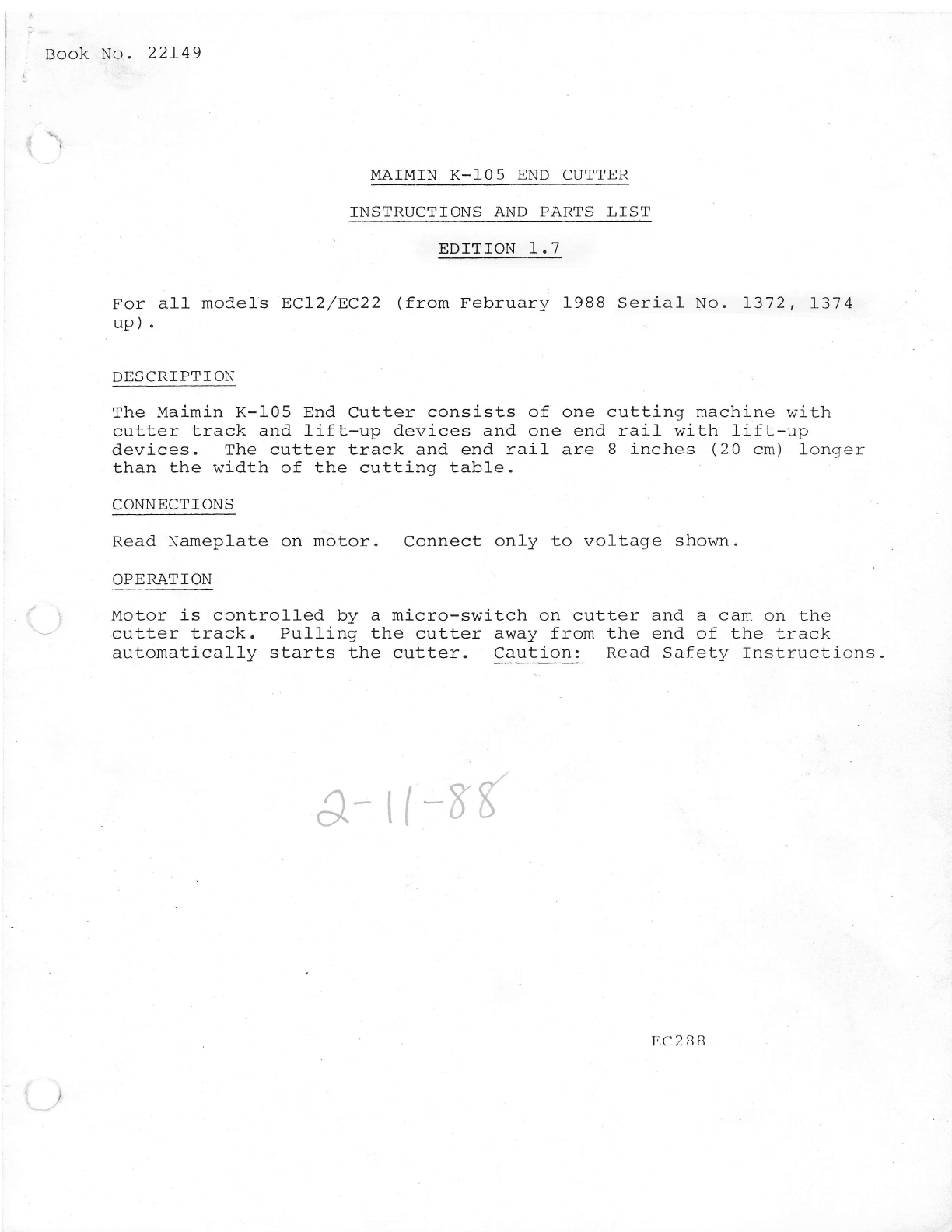
K-].05 ASSEMBLY TNSTRUCTTONS
Operator stands on side A1 of table.
Opposite side is side A2.
1. Clamp two supports A1. (10960A) and A2 (109608) to table
opposite each other.
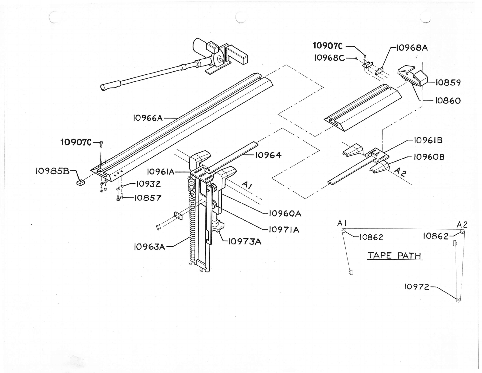
Instafl nylon tape (10964). Pass one end of tape through
top roller (10862) of track base Al (10961A) and under tape clamp
on support. Tighten tape c1amp. Pull- tape across tabte, over
top roller on track base A2 (10961A), around lower rolfer (IOg72)
and up to tape cIamp. Tighten tape clamp.
Attach cutter track (10966A) to A1 base with bolts (10857), flat-
washers (10932) , and lockwashers (1093f) . Attach cutter track to
A2 base with bracket (10859). Bracket sl_ides over track and base.
It is then l-ocked from underneath base A2 with (2) bolts (10860).
Switch release (10968A) should be at A2 end. To operate ply
counter install trip wire spring onto cutter track.*
Remove from cutter track (2) phillips pan head screws (10907C)
at A1 side. Remove shock absorber clamp (10985c) and shock
absorber (109858). rnsert standard of cutter into groove in
track with machine handle facing A1 side. Replace shock absorber,
shock absorber clamp and screws.
3.
4.
7.
B.
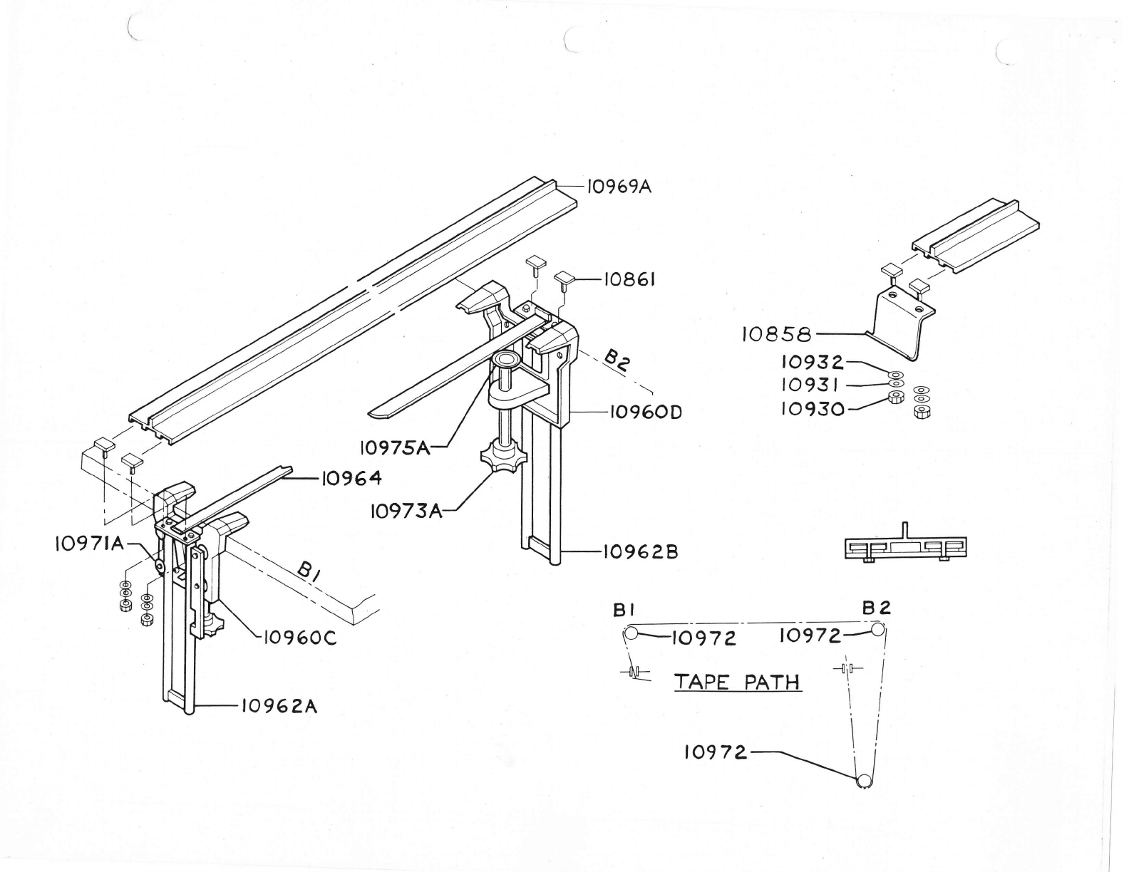
Clamp two supports 81 (10960C)
each other. 81 support should and 82 (10960D) to tabl_e opposite
be on same side as Al_.
rnstal-l nylon tape (10964). pass one end of tape throuqh top
roller (l-0972) of track base Bl (10962A) and under tape clarnf on
support. Tighten tape clamp. pull tape across table, over top
roll-er on track base 82 (10962A), around lower rol]er (rogj2) and
up to tape clamp. Tighten tape clamp,
rnsert end rail mounting T-bolts (1086r) into channels of encl
rail (10969A) . Fasten end rail with mounting T-bo]ts in channels
thru lifting handle onto end rail base with nuts (10930), ft.rt-
washers (10932) and lockwashers (10931). Repeat for other side.
Both sides of cutter track and end rail should raise equally.
Adjust tension on tape if necessary.
Cutter may be mounted in "PUSH" position if desired. Machine is
off at side Al and operator pushes machine handle to start moLor
and cut. To install in this position, mount track (10966A) with
switch release at A1 end.

rlo93o
i glo93l
.+osF
405c
1O929
;lO928A
)930 -
tog3t to976A-J 10945A-\.. lo928B
iro908 --.--
rto9sz I \
rlogoTc___- \ \
rv 7c.q,e -\ logo9
\
\'r
-\ \F;;a1,'--^
to9o7c---- \ \
\\
10906=- \ \
log06----_''--
togoS----_-_--.-i
74V
) Llo853 ;,- \roeesA
(e43A
to934A
-rtt/
7
,o9t9
t" 9"',
Ltog90
30331 --_/ 6"
szsP^V
\ r0993A/<--r
\ roesT+
,bY iloeaoA I
%t'-
to935A
lO9Zl' rp><-
R-.-';e4sB
--tog.so
logetA(120v)
t09e2A(220v1
1o948 lo7g2 --
to79+
to793
)0998
to956
937A
t0907
to946
09t6
i&!,,,, /
to9t8 /
,/
ro955
to9s4
10977
loTal --.---
roego(reov;\
to897(?aOV)
,-tozso
, rlO774
to750
4588
10909A tso72(rzov)
tso73(22ov)
€L rozsz

*/
10907C 1. -:tOg6BA
tnoLe? - \ /
'v 'vrr' \ /-l\/Tlc9f\
,Ot56g-. f, /
K4- S'o'se
J- to86o
ro985B
1O9O7C1 {\
1o961 ./
\
.'-\ \'- -""
rV ro96 tB
to960B
to972
\-t'
to 960A
lo97tA
€
€
lo963A
{toesz
ar-!0"tt
A2

to85a
.e log32>._--
lO93l --€ -
log3o r/8i 6
to96O^D
tog6?B
BI
ro975A
to964
B2
\Fibe?z ronz31
f,,- ,l* i
--uE TAPE PATH 'l I
it
lo97 z

K-105 END CUTTER PARTS LTST
PART NUMBER QUANTTTY DESCRTPTTON
102s0
10750
r07 s2
L0773
I077 4
10781
10783
lO7BB
10789
707 92
I07 93
r0794
I07 96
108 49
10850
10851
10852
108 53
10855
108 57
1OB5B
10859
1086 0
10861
10862
10900
10 901
I0902
10903
10905
10906
10907A
10907c
10909
1
2
2
2
i-
1
l-
2
2
1
3
1
I
2
Bearing
Brush
Brush Cap, FIat
Screw m3X6mm Lg. Fitlister Hd.
Cap
Fan Washer
Fan
Assembly Bolt
Washer
Undulating Washer
Washer
Retaining Ring
Bearing, Bottom
Screw m2X4mm Lg
Lint knife (not
Sprinq
. Phillips pan Hd.
(not shown)
shown)
9"r9y m4X16mm Lg. phitlips pan Hd.
Handle Spring Retainer
Screw m3X8mm Lg. Socket Hd. Cap
Bolt m6X7mm Lg. Hex Hd.
Lift Handfes
Track Bracket
Bolt m6X15mm Lg. Hex Hd.
Rail mounting T-Bo1ts
Top Tape Rol_l_er A1 & A2
Screw B-32x1 Socket Hd. Cap
419R Washer
Blade Nut
Spring
Blad.e Retainer
I) lungc r
Spring
Sharpener Bracket (Z pieces)
10908 Lockwasher M5
Screw m4X6mm Lg. phillips pan Hd.
Trip Wire
10909A Screw m4XBmm 1,9. phi:l J.ips
Pan Hd.
109098 Trip Wire Spring
Hex Nut M4
Counter
Screw m4X10mm Lg. phillips [)an ttci.
10912A Flat Washer tOmmXq,
lmmXlmm
109128 Lockwasher M4
Counter Bracket
IIand 1c
Flandle Grip
Handle Extension
Coupling Sleeve
Coupling Nut
Flexib1e Sleeve
Blade Wiper Retainer
10 910
10 911
10 912
I
1
1
1
1
4
2
1
2
6
2
2
2
1
1
1
1
1
1
I
6
1
3
I
4
1
5
4
4
1
I
1
1
1
1
I
1
10 913
10914
10 91s
10 916
LO917
10918
10 919
r0920

K-105 END CUTTER PARTS LIST
QUANTITY DESCRIPTION
PART NUMBER
'10 9 21
10 9 21A
10928A
IO92BB
L0929
10930
10931
L0932
10933
10934A
10935A
1093 6
2
4
2
2
4
1
8
L2
I2
1
1
1
1
1
I
1
1
HandIe Bracket
I0908 Lockvrasher M5
Spring Stud
Screw l45Xl5mm Lg. Phillips FIat Hd.
Screw l'l5x1Bmm Lg - Phillips Flat tid '
Counter-Irieiqht Bracket
Hex Nut M6
Lockwasher lil6
Flatrvasher 14mnX6 , TmmXImm
Counter-InIeight
Standard
l'lotor Mount
Knife Guard
10848 RollPin 2.mX5mm Lq-
10953 Screw Ir{3X6mm Lg. PhilliPs
Button Hd.
10955 Lockwasher M3
l-097 0 Flatwasher B,2mmX3'
2mmX9mm
Junction Box
Counter Cutting Blade
Screw M3X4mm Lg. Phillips trillister
Hd.
Screw l{3X4mm Lg. PhilliPs Pan Hd-
Stone Sleeve & Bearinq
109438 Stone OnlY
Screw MSXBmm Lg. Socket FId. CaP
Flatwasher IOmmX5, 3mmXlmm
Blade Oiler
Spring
10849 Screvr M2X4mm Lg. PhilliPs
Pan Hd.
Bol-t l,l6x3Omm Lq. IIex lld.
IIex Nut M5
Limit switch
Lockwasher M3
Screw M3X15mm Lg. Fillister Iid.
Support A1
Support A2
Support 81
Support 82
Track Base AssemblY Al
Track Base AssemblY A2
Rail Base AssemblY 81
Rail Base Assep"bfV B2
Spring
Nylon TaPe
Cutter Track (SPecifY l,enqth)
Switch Release
Screw M3Xl0mm Lq. Type 25 Philljr>s
Pan IId.
Screw lrl3X6mm Lg. Type 25 Phillips
Pan Hd.
10937A
10940A
10940B
10940c
.r0943A
)10 94 5A
109458
r0946
ro9 47 A
10948
10950
109 54
10955
r0956
10960A
109608
10960C
109 60D
10 9 6lA
10 9 6IB
10962A
I 09 628
10963A
10964
10966A
10968A
109688
)
- 109 6BC
1
1
1
1
1
1
4
l_
1
t-
2
6
1
2
2
I
1
1
1
I
I
1
1
3
2
1
1
2
2

K-105 END CUTTER PARTS LTST
\
PART NUMBER QUANTITY DESCRIPTION
10969A 1 End Rail (SPecifY Length)
10971A 16 Guide Roller
L0972 4 TaPe Roller
I0973A 4 Handle&Bolt
10975A 4 Pad
10976A I Sharpener Bracket Assembly
10977 L Leaf SPring with Roller
109858 2 StoP, Cutter Track
10985C Stop Clamp
10987 2 Screw M6X20mm Lg. Flat Hd.
Socket
10990 1 Motor AdaPtor Ring
10991A I Motor AssemblY 120V
109924 1 Motor Assembly 22Av
L0993A I Blade Seat w/Drive Pin
10989 - Screw, Blade Seat
M6X30mm Lg. Socket Set
Knurled Cup
10995A 1 Handle Assembly
10896 1 Armature (WK 1401912) L20v
10897 1 Armature (WK 1509612) 220v
\ 10998 1 Bottom Motor Housing
-,,/ 15072 I Top HSG e Field Assembly 120V
15073 1 Top HSG a Field Assembly 22Ov
30331 1 Round Blade
323PA I RoI1 Pin
405C 1 Terminal Block Assemblv
405F 1 Fibre
45BB l- Connector 1 Phase
45BK I Ground Shield
i

PART NUMBER
K-105 ENp CLTTER ACCESSOBTES P4CIGGE
DESCRIPTION QUANTITY
l
10 8s7
108 58
108s9
10 860
10851
10909A
109098
L0930
10931
IO932
10 9 438
10964
oil Botrle
rhillips Screwdriver
Opened end wrench BmmXl0rnrq
2.5 MM Hex Key
m6X7mn L9. Hex Hd. Bolt
Lift, Handles
Track Bracket
m6Xl5mm Lg. Hex Hd. BoIt
Rail Mounting T-Bolts
m4XSrnm Lg. Phillips Pan IId.
Screw
Trip Wire Spring
m6 Hex Nut
m6 Lockwasher
m6 Flatwasher
Stone
Nylon Tape
I
1
I
1
6
2
I
2
6
t
I
6
L2
T2
I
2
__)
J
Other manuals for K-105
1
Other maimin Cutter manuals
Popular Cutter manuals by other brands

GGM gastro
GGM gastro GEA Use & maintenance

Sparta
Sparta Huskie Tools REC-B630Y Operation manual

Office Zone
Office Zone IDEAL 4810 (18-3/4'') operating instructions

Power Fist
Power Fist 9149642 quick start guide

Z.I.P.P.ER MASCHINEN
Z.I.P.P.ER MASCHINEN ZI-BES350Y user manual

PROPOINT
PROPOINT PROCUT 30A DIGI PLUS manual