MAINLINE Kleiss MCS60-38 User manual

Kleiss MCS60-38 System Manual
Flow Stopping System / 3” - 8” up to 60 psiFlow Stopping System / 3” - 8” up to 60 psi

1
Kleiss MCS60-38 System Manual v.15 May 2020 |
www.MainlineControlSystems.com
Kleiss MCS60-38 System OverviewKleiss MCS60-38 System Overview
The Kleiss inatable stopping systems meet the needs of the North
American Natural Gas LDCs by providing a ow control system that is
easy to use and eective at stopping o ow in various pipe materials
and a wide range of pipe diameters.
The Kleiss MCS60-38 System consists of four major components:
1) tting to access the pipe, 2) tapping / completion tool, 3) inatable stopper, and 4) stopping tool.
The Kleiss MCS60-38 System (all tools) has a maximum operating pressure of 60 psi. The inatable stoppers have a
design safety factor of 3. The balance of the tools have a design safety factor of 2.5.
The Kleiss MCS60-38 System is designed to handle ow control on pipe sizes 3” to 8” on all pipe material – cast iron,
polyethylene, steel and PVC pipes. To accommodate the various pipe materials and sizes the tapping tool and stopping
tool are outtted with the appropriate tting, cutter, chute, and stopper. See the Sizing Table in Section 4.0 to identify and
install the correct components before operating the equipment.
The basic operation of the equipment is the same for all pipe materials. When working on non-metallic pipe materials,
make sure the equipment is grounded per your company operating practices.
(Kleiss & Co., who developed the system, has reviewed and approved this manual.)
Table of Contents:
1.0 General Safety Information: .................................................. 2
2.0 System Specications: ........................................................... 2
3.0 Typical Site Set Up and Sequence: ........................................ 4
4.0 Equipment: ............................................................................. 9
5.0 Preparatory Steps: ................................................................ 16
6.0 Tapping Operation: .............................................................. 16
7.0 Stopping Operation: ............................................................. 23
8.0 Retrieving MDS Stopper: .................................................... 32
9.0 Plugging Operation: ............................................................. 36
10.0 General Maintenance: ........................................................ 40
APPENDIX A: Stopper Testing and Verication....................... 41
APPENDIX B: Tower Positioning and Distances ..................... 43
APPENDIX C: Manual Updates ................................................ 47

2
Kleiss MCS60-38 System Manual v.15 May 2020 |
www.MainlineControlSystems.com
1.0 General Safety Information:
NOTE: Before using the Kleiss MCS60-38 System make certain you read the instruction manual completely and are
comfortable and familiar with the operation of the tools. If you have any questions, concerns or feel there is conicting
information, please contact Mainline Control Systems (MCS) before proceeding at 844-FLO-STOP.
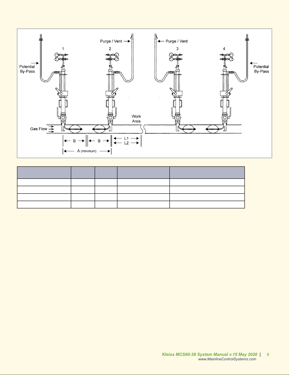
NOTE: The purpose of the Kleiss MCS60-38 System is to tap and stop ow in natural gas lines sizes 3” through 8”
operating at a maximum of 60 psi. Review and follow your company safety procedures for operations involving tapping
and stopping live natural gas lines.
NOTE: When operating the Kleiss MCS60-38 System on non-metallic pipe materials, please follow company procedures
for grounding equipment for discharge of any static electricity.
2.0 System Specifications:
2.1 General2.1 General
A) Pipe diameter between 3” and 8”
B) Pipe material of cast iron, polyethylene, steel or PVC
C) Maximum operating pressure of 60 psi
NOTE: Tools are designed and built with a safety factor to allow +10% (+6 psi) for operation on 60 psi MAOP
systems or in abnormal operating conditions.
D) Tool to tting connection of 2-1/2” BSP threads
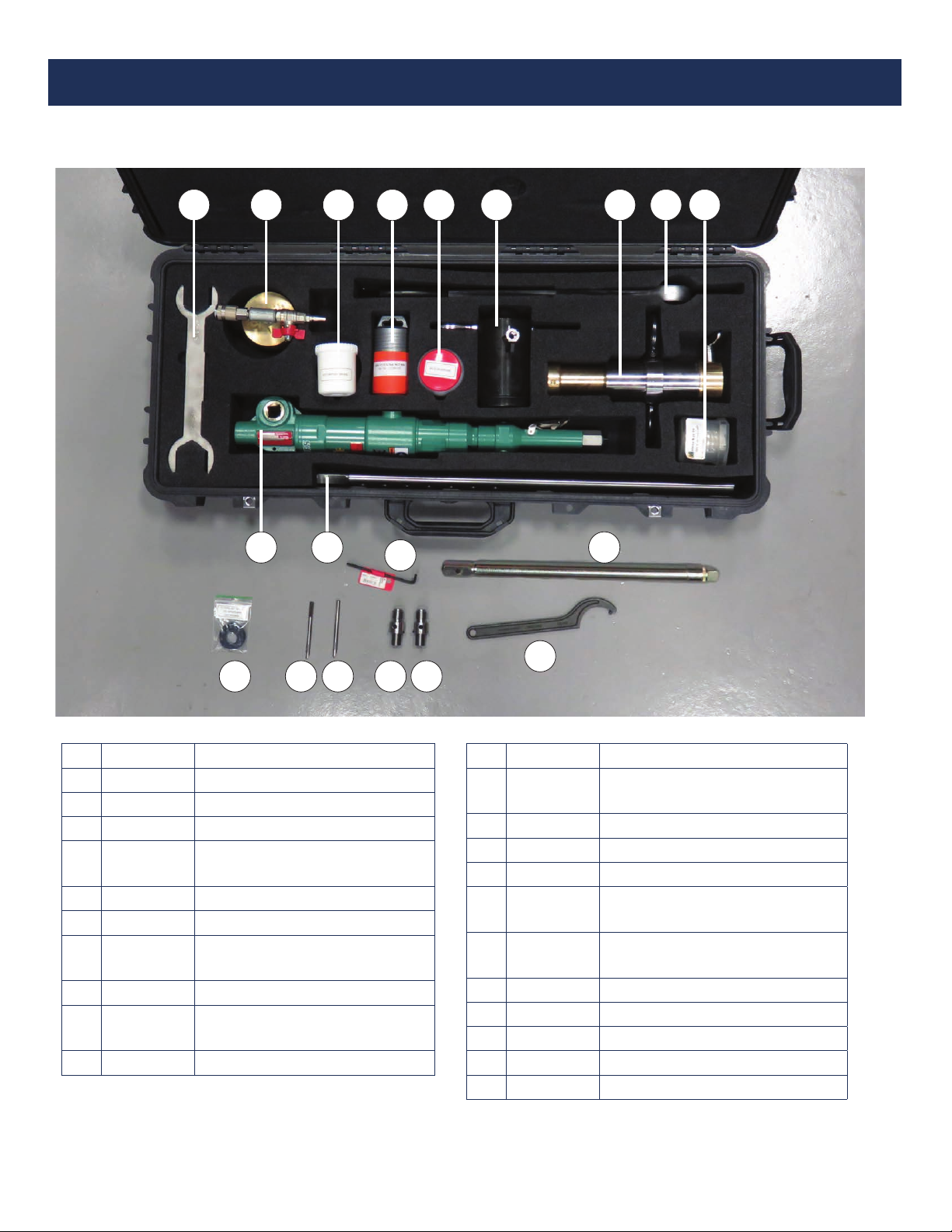
2.2 Tapping Tool and Completion Tool Kit Specications2.2 Tapping Tool and Completion Tool Kit Specications
A) Maximum operating pressure of 60 psi (see NOTE in 2.1C)
B) Cutters available
a) 2.2” (56.5 mm) cast iron and steel [Part #13200140]
b) 2.2” (56.5 mm) polyethylene and PVC [Part #1310080]
C) 1/4” (6.3 mm) pilot drill used for all materials [Part #14300060]
D) Air motor & compressor requirements
a) Connection to the air motor ~ 3/4” NPT
b) 90 psi measured at the inlet of the air motor during operation
c) Air volume through the motor should operate the air motor at 35 RPM’s load speed (cut) & 70-75 RPM’s free
speed (non-cut)
d) Refer to manufacturer air motor specications guide
E) Oiler / separator required to be used to extend the life of the air motor
a) Use standard pneumatic oil in tool
F) Weights
a) Tapping tool with cutter ~ 23 lbs.
b) Completion tool without completion plug attached ~ 13 lbs.
c) Air motor ~ 11 lbs.
d) Shipping weight in case ~ 65 lbs.
G) Dimensions
a) Tapping tool height with cutter ~ 29”
b) Completion tool height ~ 17”
c) Storage case ~ 38” length x 18” width x 6” height

3
Kleiss MCS60-38 System Manual v.15 May 2020 |
www.MainlineControlSystems.com
2.3 Stopping Tool Kit Specications2.3 Stopping Tool Kit Specications
A) Maximum operating pressure of 60 psi (see NOTE in 2.1C)
B) Weights
a) Stopping tool ~ 46 lbs.
b) Ball valve ~ 8 lbs.
c) Shipping weight in case ~ 94 lbs.
C) Dimensions
a) Stopping tool height with stopper rod completely extended ~ 7 feet
b) Stopping tool height with stopper set ~ 4 feet
c) Storage case ~ 56” length x 16” width x 12” height
D) By-pass / vent port
a) 3/4” tap size in tool
b) 1” camlock male coupling
2.4 MDS Inatable Stopper Specications2.4 MDS Inatable Stopper Specications
A) Sizes
a) 2.75” – 3.54” (70 mm – 90 mm) Pipe ID [Part #23100353]
b) 3.54” – 4.72” (90 mm – 120 mm) Pipe ID [Part #23100354]
c) 4.72” – 6.29” (120 mm – 160 mm) Pipe ID [Part #23100355]
d) 6.29” – 8.46” (160 mm – 215 mm) Pipe ID [Part #23100356]
B) Ination pressure of 120 psi or 2x system pressure if unable to achieve 120 psi by compressor or nitrogen
C) Design burst pressure of 350 psi
D) Operating temperature range of 5° F (- 15° C) to 140° F (60° C)
E) Maximum temperature range of 158° F (70° C) for up to 30 minutes
2.5 Vent Stack Specications2.5 Vent Stack Specications
A) Height assembled ~ 112”
B) 1” camlock male coupling
C) Air hose to venturi connection
D) Hose (standard) of 10 m, 1” camlock connection F x F
E) Ground rod included
F) Weight (less hose) ~ 27 lbs.
G) Air supply and ow capacity rates =
Air Supply Flow Capacity
Working Pressure
(PSI)
Air Consumption
(ft3/min)
Blow Out Volume
(ft3/hr)
80 13 24300
120 13 21200

4
Kleiss MCS60-38 System Manual v.15 May 2020 |
www.MainlineControlSystems.com
2.6 Hand Pump (Pressure and Vacuum Pump)2.6 Hand Pump (Pressure and Vacuum Pump)
A) 1 positive pressure connection
B) 1 negative pressure (vacuum) connection
C) 10 foot air hose with quick disconnects included
D) Weight ~ 12 lbs.
2.7 Maximum Flow Rates2.7 Maximum Flow Rates
A) Maximum design ow rate = 22 ft/sec (7 m/sec)
B) For reducing speed, use by-pass / vent port
NOTE: The system is designed to be used in controlled stop o applications, and is not intended to be used to
stop ows in severely ruptured pipes. Flow should be reduced before attempting stop o.
3.0 Typical Site Set Up and Sequence:
It is important to understand the MCS stopping tools and their operation completely. It is also important to understand the
complete job and sequence of steps to perform a safe stop. Safety of the operators on the job site is the most important
factor so pre-plan the whole job including the stopping and retrieval sequences.
The following examples are typical installations. Example I (yellow background) illustrates stoppers positioned towards
each other. Example II (blue background) illustrates stoppers positioned away from the work area. Both congurations
work equally well. For additional set up illustrations, see Appendix B or contact your distributor / MCS representative.
Remember to consider the ancillary steps like purging / venting the area to be worked on and back pressuring stoppers for
removal. The features of the MCS60-38 oer options to make these processes ecient.
Table of contents
Other MAINLINE Industrial Equipment manuals