Major Manufacturing HIT-41 SERIES User manual

INSTRUCTIONS
FOR
HIT-41 SERIES
ELECTRIC STRIKE
TEMPLATES
1825 VIA BURTON
ANAHEIM CA 92806
714-772-5202 / FAX 714-772-2302
WEB: WWW.MAJORMFG.COM
WHEN USING POWER TOOLS
ALWAYS WEAR
EYE AND EAR PROTECTION!!

STOP!
PLEASE READ ALL INSTRUCTIONS
BEFORE ATTEMPTING TO USE.
YOUR ROUTER MUST BE EQUIPPED
WITH A TEMPLATE GUIDE PRIOR TO
USE. FAILURE TO DO SO WILL
RESULT IN THE WRONG SIZE
OPENING IN THE DOOR OR JAMB
AND POSSIBLE DAMAGE TO YOUR
ROUTER TEMPLATE.
ALUMINUM DOOR TEMPLATES
REQUIRE A 3/8”OUTSIDE DIAMETER
TEMPLATE GUIDE
WITH A 1/4” DIAMETER BIT.
2

MAKE ADJUSTMENTS TO ALL DOOR HARDWARE
PRIOR TO INSTALLING ELECTRIC STRIKE. THE
DOOR MUST SWING SMOOTHLY IN OPENING FOR
LOCK AND STRIKE TO FUNCTION PROPERLY.
MAKE CERTAIN THAT YOU ARE USING THE
CORRECT TEMPLATE FOR THE STRIKE BEING
INSTALLED AND YOUR ROUTER HAS A 3/8”
OUTSIDE TEMPLATE GUIDE INSTALLED
IN THE BASE.
GENERAL SAFETY RULES
ALWAYS WEAR EYE AND EAR PROTECTION!!
Before attempting any installation know how to safely use
the power tools involved and how they work. Be sure all
bits and cutters are sharp and in good condition and all
power cords and extension cords are in good working
order and properly grounded.
Always make sure the router comes to a COMPLETE
STOP before pulling it away from the template. Failure to
do so may cause damage to your router template, your
work or personal injury.
Always route in a CLOCKWISE direction. A
counterclockwise direction will cause the router bit to
climb in the cut and cause an unstable situation.
If you feel you have missed part of the cut, DO NOT
BACK UP!! You will be making a clean up pass that will
take care of the problem.
3

These are the most important tools that you will use in this installation.
Always use eye and ear protection!!
Your router needs to be equipped with a 3/8”
outside diameter template guide mounted in
its base. Failure to use a template guide will
cause the opening being routed to be too
large and will damage your HIT-41 template.
See our catalog or web site for a list of
available router template guides.
Install a 1/4” diameter aluminum cutting
router bit into the router collet and secure
tightly. Do not bottom the bit in the collet, hold
it about 1/16” from bottoming. Adjust the
router bit so it will route about 1/4” to 3/8” into
the door channel.
The electric strike being installed in the following
demonstration is for an offset hung door. There are strike
models available for both offset and center hung doors.
If mounting in a center hung jamb, be sure there is
depth clearance for the strike!
Our web site has a complete listing of templates.
4

For height alignment, let
the door close into the
jamb.
With a pencil, locate the
top and bottom of the
latch
Transfer these lines to the front and side of
the jamb with the use of a combination
square.
With a combination square, establish the
centerline of the strike. The door and strike
need to have the same center line. For a
standard 1-3/4” door this dimension is 7/8”
from the door stop if the lock is centered in
the door channel. If the lock is off center,
adjust accordingly. The face of the electric
strike and the face of the lock must be
centered together when the door is closed.
5

Align the HIT-41 template to the pencil marks
and attach to the jamb using tek point dry
wall screws. It is a good idea to use a drill
with a clutch feature, you don’t want to snap
the screw off in the jamb.
Some HIT-41 templates have one screw hole
top and bottom and some have two. These
holes will align the factory mounting tabs
needed later, some factory tabs are mounted
with one and some with two. How many are
needed depends on the strike you are using.
One screw top and bottom will hold the
template. The second hole for the tab can be
located by drilling with a 9/64” drill bit or by
using a second screw.
Template mounted and ready to go.
We recommend the area to be routed be
lubricated with a cutting lube. We use a
product called Tapmatic Edge Cream made
by the LPS Company. You can find this
product at industrial hardware stores or
machine shop supplies. This is also a handy
product to use for other drilling or tapping
chores.
6

Note that we did not route through the top of
the lip area, this will be cut out with the next
pass. If you run through the side wall you
run the risk of hitting the template with the
router bit.
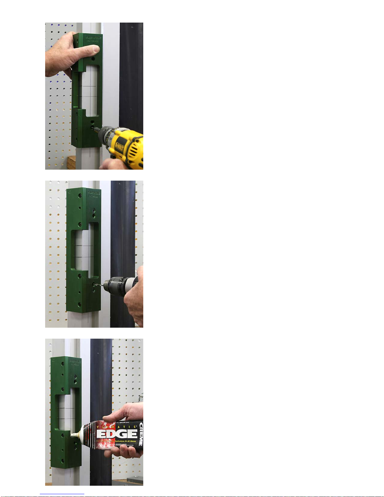
Adjust the router bit so it is about 1/4” past
the aluminum as shown.
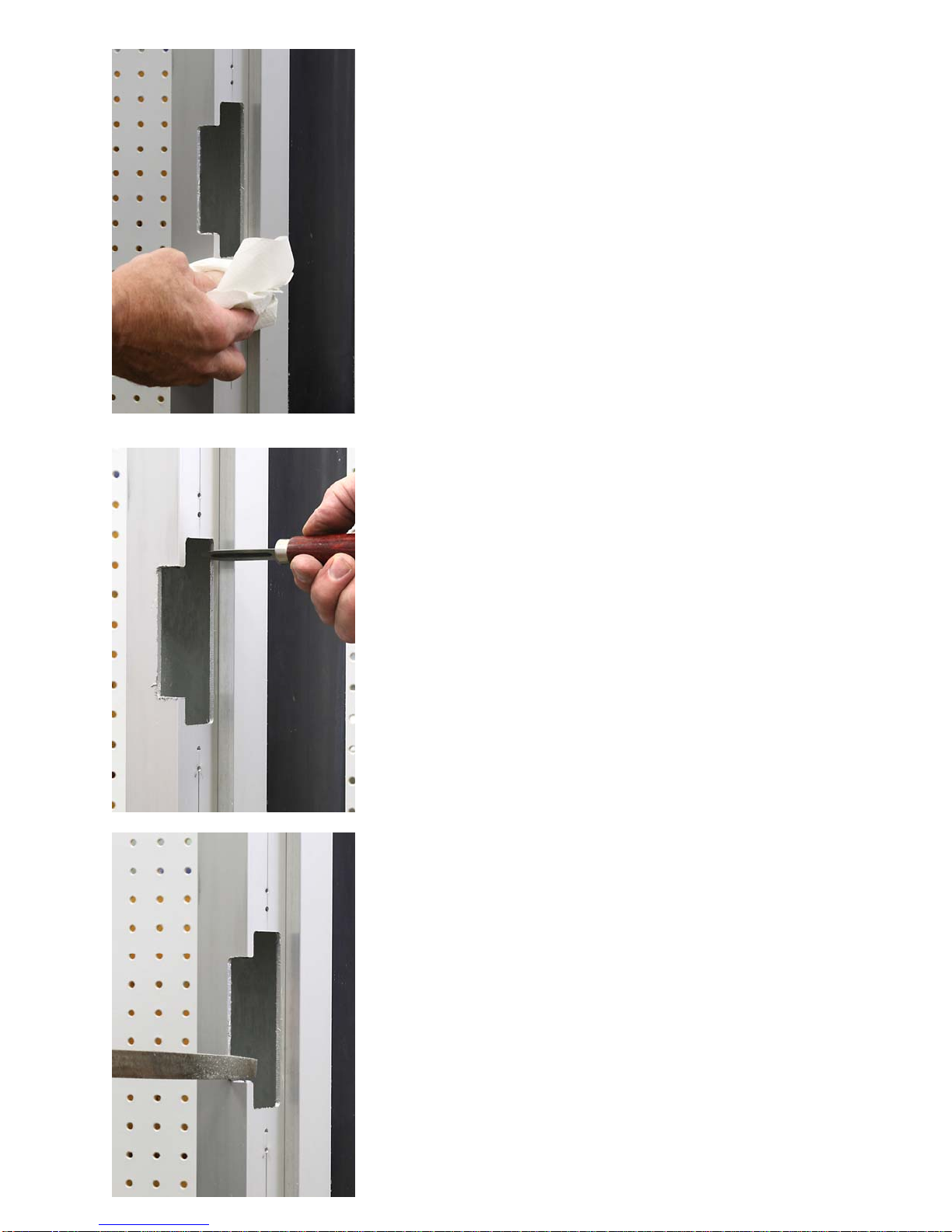
Place the router at the bottom of the
template, you will be routing the lip area first,
routing clockwise starting at the bottom. Let
the router come to full speed and route
through the side of the jamb. Be sure to hold
the router flat against the template and DO
NOT BACK UP IN THE CUT. When
completed at the top, LET THE ROUTER
COME TO A COMPLETE STOP BEFORE
REMOVING IT FROM THE TEMPLATE.
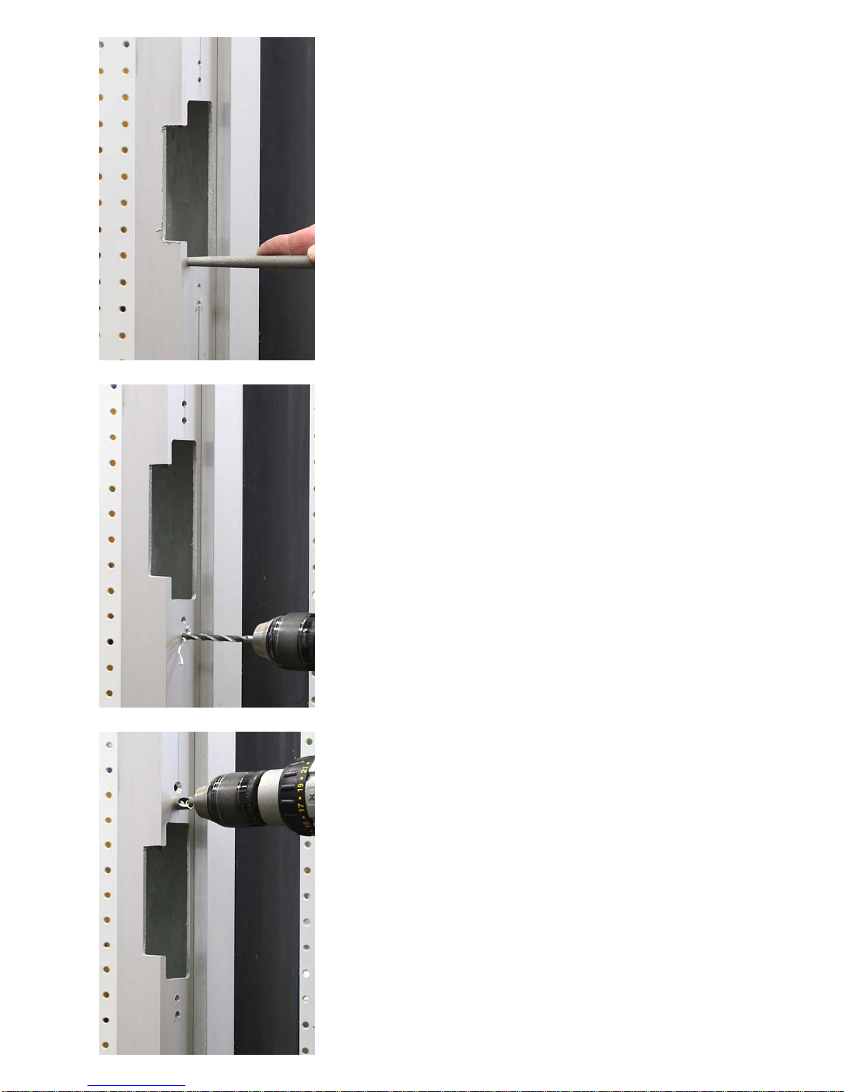
Place the router at the top of the template,
you will be routing the faceplate area. The
router guide should be touching the electric
strike template with the bit not making con-
tact with the frame. Let the router come to full
speed and route through the side of the
jamb. Be sure to hold the router flat against
the template and DO NOT BACK UP IN THE
CUT. When completed at the top, LET THE
ROUTER COME TO A COMPLETE STOP
BEFORE REMOVING IT FROM THE
TEMPLATE
7

Brush the aluminum chips from the router guide to
prepare for the second clean up pass.
After making the first pass, brush away the chips
and make a second clean up pass. Use the same
procedure as before.
Remove the electric strike template from the
jamb.
8

Use a machinist scraper or an aluminum cutting
file and deburr all of the openings.
Clean the area of left over cutting lube and chips.
Be sure to use a brush to remove the chips, they
are sharp!
Don’t forget to square off the corners for the lip
area in front of the front of the frame, the router
will leave these round.
9

If the installation calls for a round corner faceplate,
lightly touch up this area with a round file.
If you are installing a strike with a square
faceplate, square these with a flat file.
Now is the time to drill out the holes needed for
the factory mounting tabs. Use a 3/16” drill bit for
this job.
Note: the template in this case uses two mounting
holes top and bottom, some strikes only require
one hole so your template may vary from the
picture.
Counter sink the mounting holes.
10

Install factory mounting tabs, leave them a little
loose and tighten after the strike has been
installed.
Prep is complete and ready to install mounting
tabs and strike.
Connect the wire leads and insert strike into the
frame.
11

Install strike to factory mounting tabs and
tighten all of the mounting screws.
Finished installation.
That’s all there is to it!!
Visit our web site at www.majormfg.com for more
information on router recommendations, template
guides and a complete listing of electric strike
templates to make your installations easier and
faster. While there, sign up for our
newsletter and we will email new product information
directly to you.
12
Table of contents
Other Major Manufacturing Door Lock manuals
Popular Door Lock manuals by other brands

LOCKEY USA
LOCKEY USA 1150 installation instructions

CISA
CISA SIKUREXIT 43295 Series instruction sheet

Kwikset
Kwikset Kevo Installation and user guide

Wayne-Dalton
Wayne-Dalton Keyed-in-Handle Autolatch ECR Lock Installation instructions and owner's manual

Arregui
Arregui CI10 instructions

Assa Abloy
Assa Abloy SARGENT Profile Series installation instructions