MAKERGEAR V4 Hot End User manual

V4 Hotend and Rev.F/G Cooling Upgrade
Installation Guide
Last edited on 10/04/2022

2
Please verify the printer is OFF and the power is disconnected before disassembling
▶x1- Filament drive / Fan assembly
▶x1 - V4 Hotend
▶x1 - Z-Endstop (Max)
▶x1 - Extruder mounting plate
▶x1 - Belt clamp
▶x1 - Metal motor mount
▶x1 - Printed wiring box and lid
▶x1 - M3x12 socket head screw
▶x2 - M3x14 socket head screws
▶x4 - M3x18 athead screws
▶x1 - M3x20 socket head screw
▶x3 - M3x28 socket head screws
▶x1 - M3x45 athead screw
▶x8 - Zip ties (4in)
List of components:

Step 1: Disassembling the original v3b extruder assembly
Removing the lament drive and fans assembly
• Cut and remove the zip tie on the right side of the lament
drive to free the fan wires
• Disconnect the hotend and fan cables
• Loosen and remove the (x1) M3x40 screw from the top-le
hole on the extruder motor fan and then remove the fans
• Remove both of the M3x25 screws that are holding the
lament drive in place
(You will reuse both M3x25 screws later in this upgrade)
• Remove the lament drive
Removing the motor and mounting plate
• Cut the (x3) zip ties on top of the extruder wiring harness
• Loosen the (x2) M4x35 screws so that the motor can be slid
out from the back
• Remove the motor along with the extruder wiring harness
and then set them aside to reuse later
• Remove the (x4) M3x12 screws that aach the printed extuder
motor mount to the X-axis carriage
• Remove the printed extruder motor mount
• Remove the (x4) M2x16 screws from the extruder mounting
plate and then remove the mounting plate
• Remove the printed belt clamp from the X-axis belt
M2 - Revision E Users:
Please note, the extruder and motor mounts look slightly
dierent, but the basic concept remains the
same. Remove all of the extruder components
until only the carriage is le
3

Installing the new belt clamp and mounting plate
• Install the new belt clamp on the front belt span with the ns
facing the back of the printer
• Place the new extruder mounting plate on top of the belt
clamp and the X-axis carriage
• Insert and tighten the (x4) M3x18 screws through the back
four mounting plate screw holes to secure the belt clamp
• Insert the (x2) M3x10 screws through the two rearmost holes
to tighten the mounting plate to the X rail carriage
• Place the new motor mount on top of the mounting plate with
the printed wiring box facing the rear
• Insert (x2) M3x14 screws and tighten while pulling the motor
mount towards the front
• Noting the location of the connector, remove the three M3
bolts from the extruder motor using a 2.5mm wrench
• Place the motor through the motor mount with the connector
facing right
• Insert and tighten the (x3) M3x28 screws to secure the motor
Parts needed for this step:
• x1 - Extruder mounting plate
• x1 - Belt clamp
• x1 - Metal motor mount with printed wiring box
• x2 - M3x14 socket head screws
• x3 - M3x28 socket head screws
• x2 - M3x10 athead screws
• x4 - M3x18 athead screws
Step 2: Install the extruder mounting plate 4

Removing the extruder harness
• Cut and remove the zip ties that secure the extruder harness
to the printer
• Please review the comparison photo. Your harness should
look like the top harness and you’ll need to adjust it to
look like the boom harness
• Snip the cable ties that hold the cables inside of the braided
wiring loom
Step 3: Wiring harness adjustment and installation 5
Adjusting the extruder harness
• Pull the wires through the harness so there is only 1” of each
wire sticking out of the loom
• Pull the wire with the white connector in the loom all the way
to the end
• Reapply cable ties to the harness
• Plug the white connector into the extruder motor through the
wiring box
• Install the wiring box lid with a 2mm allen wrench. is takes
a lile torque as the screws are tapping themseleves into
the printed part

Parts needed for this step:
• x1- Filament drive / Fan assembly
• x1 - v4 Hotend
• x1 - M3x45 athead screw
• x1 - M3x12 socket head screw
• x2 - M3x25 socket head screws and washers
(reused from the original lament drive)
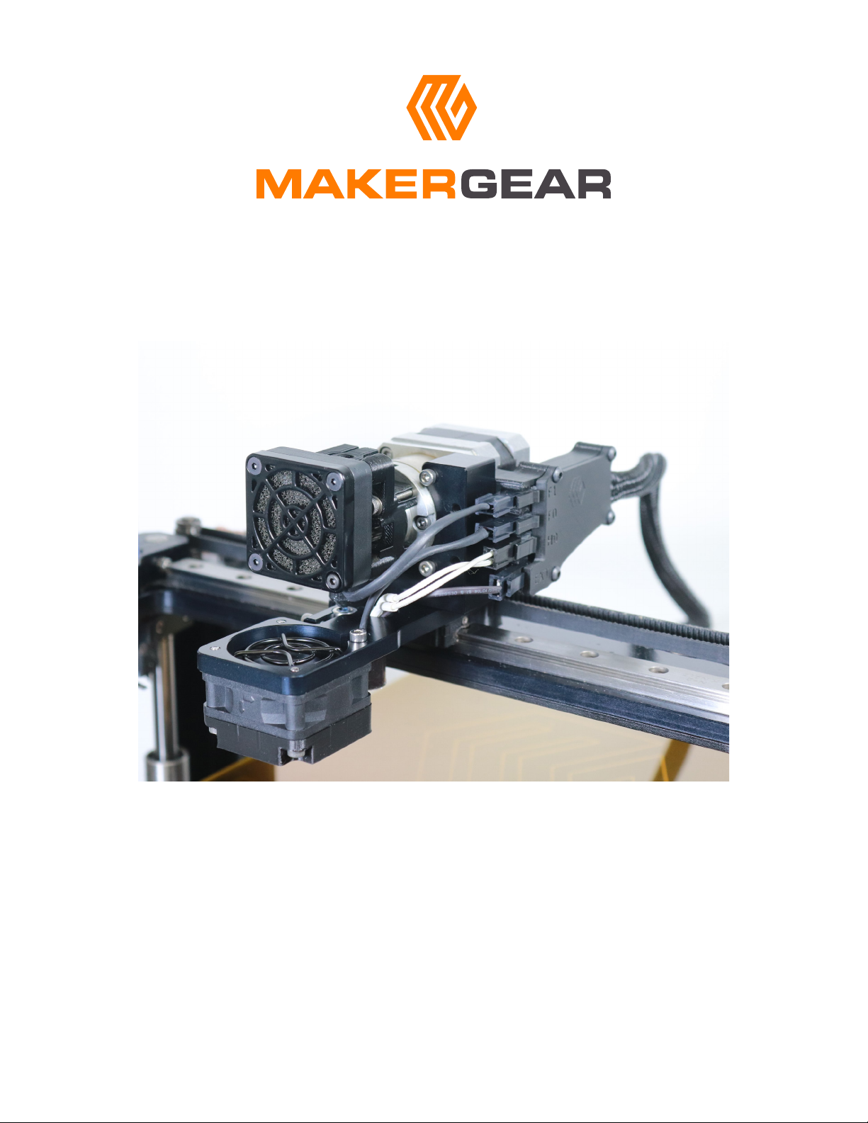
Hotend installation
• Insert the (x1) M3x12 screw into the hole on the side of the
extruder mounting plate (Don’t tighten yet)
• Insert the hotend into the sloed hole, with the top of the
hotend ush with the mounting plate
• Individually feed both of the hotend cables through the hole
just in front of the motor mount
• Rotate the hotend so the black and white wires ow freely
through their hole
• Tighten the (x1) M3x12 screw securing the hotend into place
• Connect the white hotend cable to the “H0” connector in the
wiring box
• Connect the black hotend cable to the “EXT” connector in the
wiring box
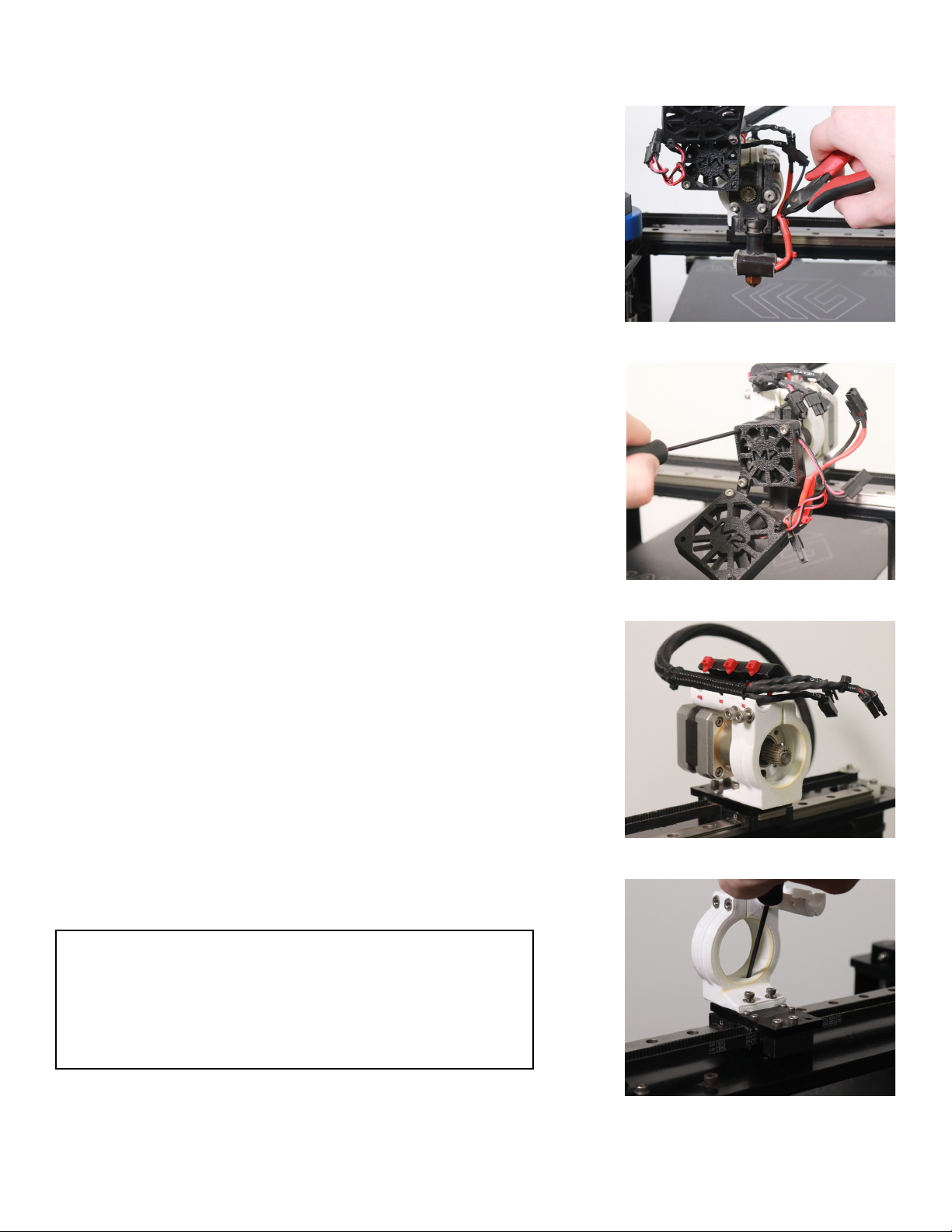
Filament drive installation
• Rotate the fan on the lament drive in order to clearly see
all parts of the lament drive
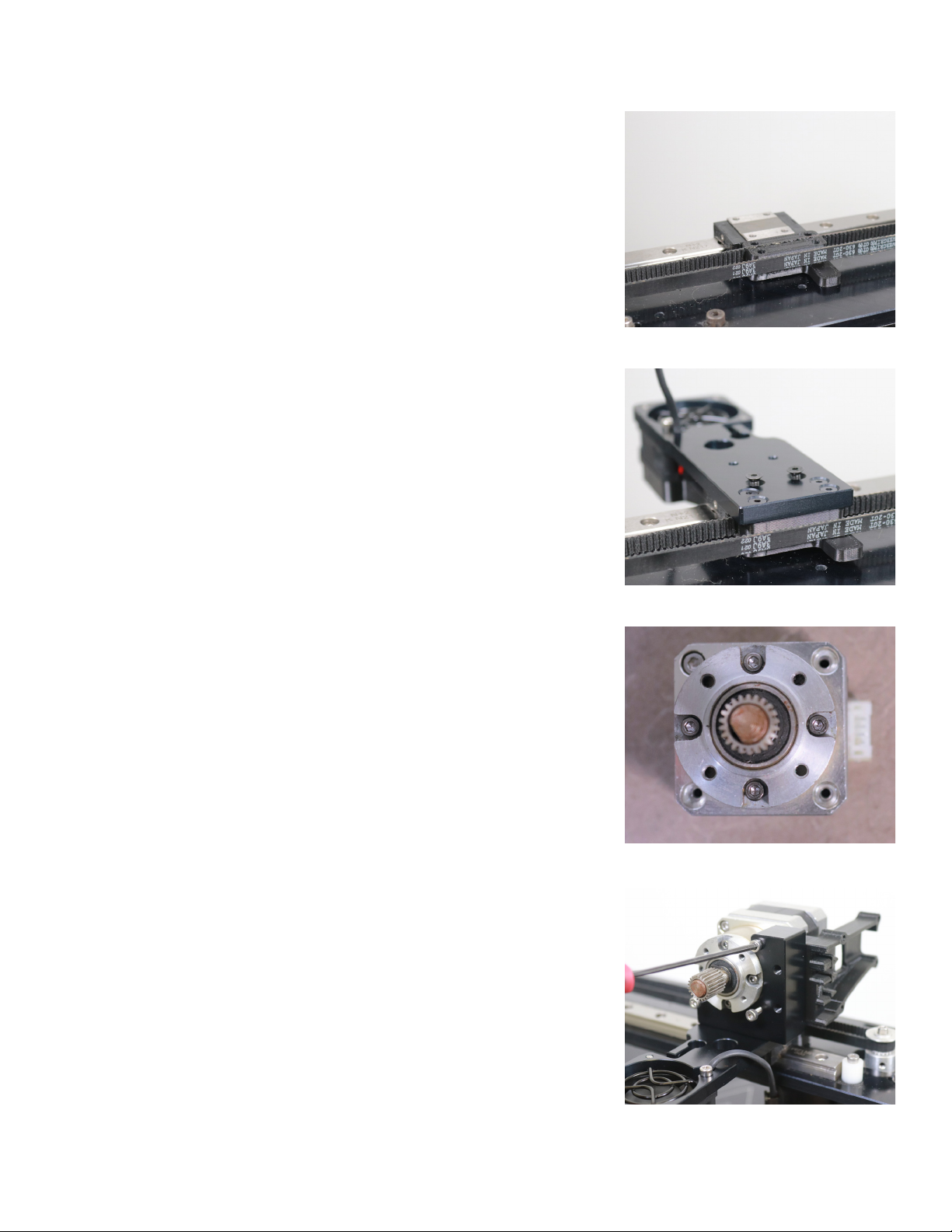
• Place the lament drive around the extruder motor with the
at surface touching the motor face
• Insert the (x2) M3x25 screws and washers into the top right
and boom le holes into the front of the lament drive
• Align the lament drive with the top of the hotend, then
tighten the lament drive down
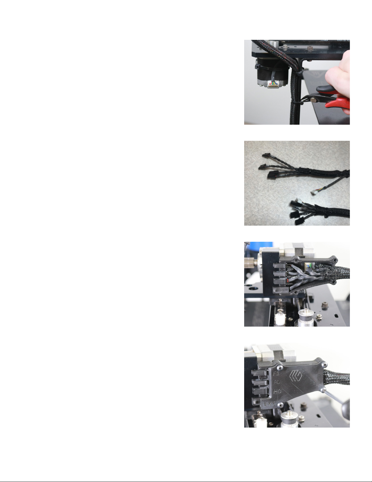
• Rotate the fan on the lament drive so the empty hole is in
the lower right. Insert the (x1) M3x45 screw and tighten
• Connect the extruder motor fan to the “F1” connector in the
wiring box
• Connect the part cooling fan to the “F0” connector in the
wiring box
Step 4: Filament Drive, fan, and hotend assembly 6

Parts needed for this step:
• x1 - M3x20mm socket head screw
• x1 - Z-Endstop (Max)
Z-Min (top) switch removal
• Use an 7mm (or adjustable) wrench to loosen the jam nut
underneath the Z-stage
• Remove the old Z-adjustment screw by hand
Z-Max (bottom) switch installation
• Snap the new Z-endstop bracket onto the far smooth Z-rod
• Slide the Z-endstop bracket to the boom of the printer
• Rotate it so the lever arm is pointed at the front smooth Z-rod
• Insert the (x1) M3x20mm into the Z-end endstop bracket
• Tighten the screw into the lock nut with a 2.5mm allen
wrench
Plugging in the Z-max (bottom) switch cable
• Slightly open the enclosure and then unplug both the case fan
and SD card reader cables
• Pivot the enclosure to rest it on its le side
(e bed will need to be lied to do this)
• Plug the new Z-endstop into the Z-max endstop port on the
RAMBo board
• Plug the SD card reader cable back in
• Secure the electronics enclosure
Step 5: Replace the Z-endstop switch 7
RAMBo board wiring:

• Visit rmware.makergear.com
• Watch the video for instructions on how to upload rmware
• Use the rmware selector
• Download and install the rmware
Please contact us at “support@makergear.com” if you encounter any issues installing the upgrade
Step 6: Upload the new rmware
8
Table of contents