Makita HS010G User manual

HS010G
EN Cordless Circular Saw INSTRUCTION MANUAL 9
FR Scie Circulaire sans Fil MANUEL D’INSTRUCTIONS 21
DE Akku-Handkreissäge BETRIEBSANLEITUNG 35
IT Sega circolare a batteria ISTRUZIONI PER L’USO 49
NL Accucirkelzaag GEBRUIKSAANWIJZING 63
ES Sierra Circular Inalámbrica MANUAL DE
INSTRUCCIONES 78
PT Serra Circular a Bateria MANUAL DE INSTRUÇÕES 93
DA Ledningsfri rundsav BRUGSANVISNING 107
EL 120
TR Akülü Sunta Kesme KULLANMA KILAVUZU 135

Fig.1
Fig.2
Fig.3
Fig.4
Fig.5
Fig.6
3
2
1
Fig.7
2

1
2
Fig.8
2
1
Fig.9
1
Fig.10
1
2
Fig.11
1
Fig.12
1
Fig.13
2 1
Fig.14
3

1
Fig.15
1
Fig.16
1
Fig.17
1
2
4
3
5
6
Fig.18
1
2
4
5
3
6
7
Fig.19
1
2
3
4
Fig.20
12
3
4
5
Fig.21
4

12
3
4
5
Fig.22
12
3
4
5
6
Fig.23
1 2 3
Fig.24
1
Fig.25
1
2
1
5
6
3
4
2
3
Fig.26
Fig.27
1
Fig.28
1
2
Fig.29
5

Fig.30
1
Fig.31
1
2
3
4
Fig.32
1
2
3
Fig.33
1
Fig.34
6

1 2
1
2
Fig.35
Fig.36
1
Fig.37
1
2
Fig.38
1
Fig.39
1
Fig.40
7

1 2
1
2
Fig.41
12
Fig.42
1
Fig.43
8

9ENGLISH
ENGLISH (Original instructions)
SPECIFICATIONS
Model: HS010G
Blade diameter 235 mm
Max. Cutting depth at 0° 85 mm
at 45° bevel 61 mm
at 60° bevel 41 mm
No load speed 4,000 min-1
Overall length 430 mm
Rated voltage D.C. 36 V - 40 V max
Net weight 5.5 - 6.1 kg
without notice.
-
est combinations, according to EPTA-Procedure 01/2014, are shown in the table.
Applicable battery cartridge and charger
BL4020 / BL4025 / BL4040 / BL4050F*
Charger DC40RA / DC40RB / DC40RC
residence.
WARNING: Only use the battery cartridges and chargers listed above.
Intended use
appropriate Makita genuine saw blades, other materials
can also be sawed.
Noise
-
ing to EN62841-2-5:
pA
NOTE:
been measured in accordance with a standard test
another.
NOTE:
exposure.
WARNING: Wear ear protection.
WARNING: The noise emission during actual
value(s) depending on the ways in which the
tool is used especially what kind of workpiece is
processed.
WARNING: Be sure to identify safety mea-
sures to protect the operator that are based on an
estimation of exposure in the actual conditions of
use (taking account of all parts of the operating
cycle such as the times when the tool is switched
trigger time).
Vibration
-
mined according to EN62841-2-5:
2or less
2
h,M 2or less
2

10 ENGLISH
NOTE:
measured in accordance with a standard test method
NOTE:
WARNING:
The vibration emission during actual
-
ue(s) depending on the ways in which the tool is used
especially what kind of workpiece is processed.
WARNING:
Be sure to identify safety measures
to protect the operator that are based on an estima-
tion of exposure in the actual conditions of use (tak-
ing account of all parts of the operating cycle such
it is running idle in addition to the trigger time).
EC Declaration of Conformity
For European countries only
to this instruction manual.
SAFETY WARNINGS
General power tool safety warnings
WARNING: Read all safety warnings, instruc-
with this power tool. Failure to follow all instructions
Save all warnings and instruc-
tions for future reference.
Cordless circular saw safety
warnings
Cutting procedures
1. DANGER: Keep hands away from cutting
area and the blade. Keep your second hand
on auxiliary handle, or motor housing. If both
the blade.
2. Do not reach underneath the workpiece. The
workpiece.
3. Adjust the cutting depth to the thickness of
the workpiece. Less than a full tooth of the blade
teeth should be visible below the workpiece.
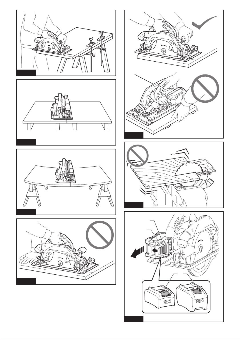
4. Never hold the workpiece in your hands or
across your leg while cutting. Secure the
workpiece to a stable platform. It is important to
-
sure, blade binding, or loss of control.
Fig.1
5. Hold the power tool by insulated gripping
surfaces, when performing an operation where
the cutting tool may contact hidden wiring.
Contact with a “live” wire will also make exposed
metal parts of the power tool “live” and could give
the operator an electric shock.
6. When ripping, always use a rip fence or
straight edge guide.
of cut and reduces the chance of blade binding.
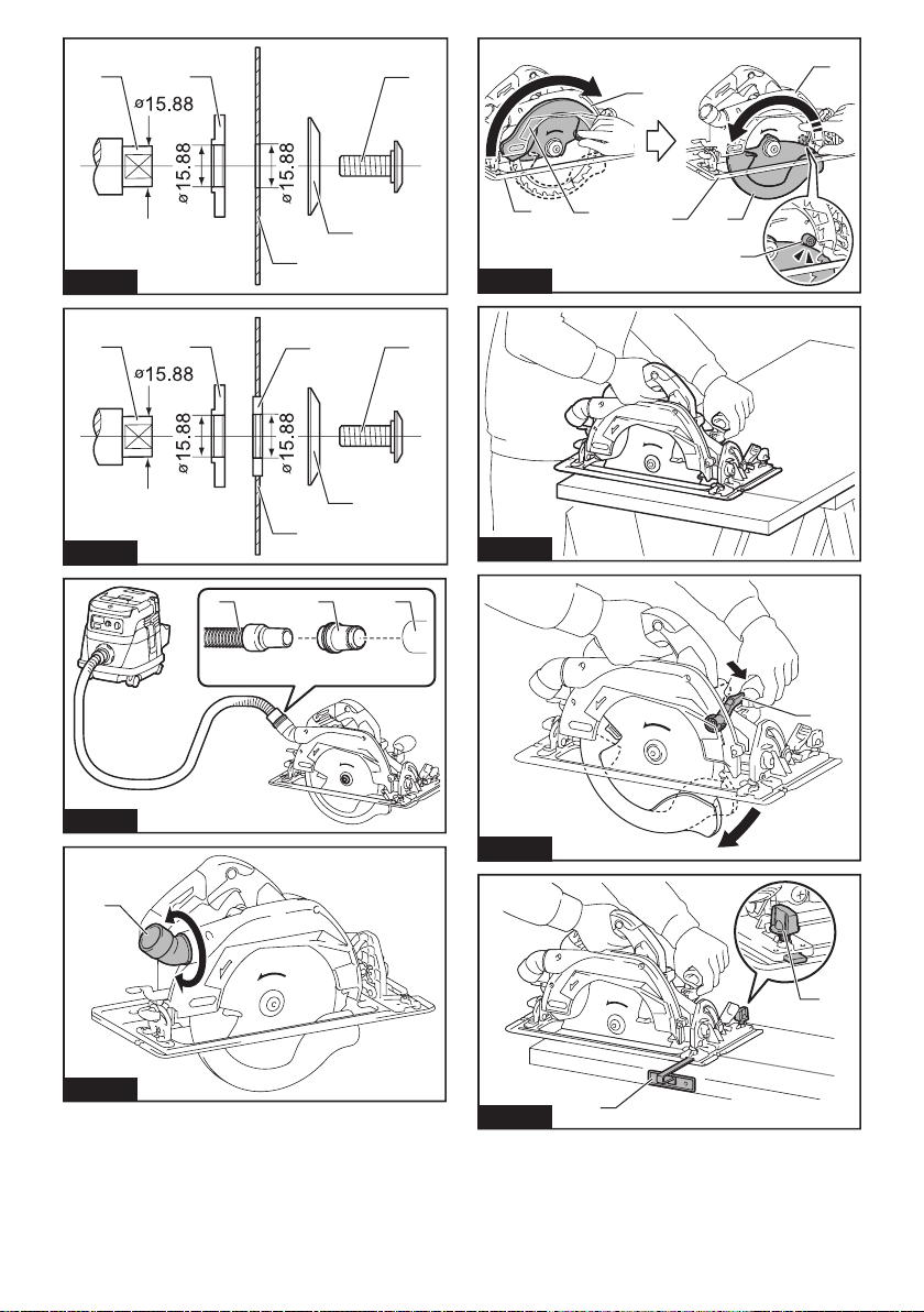
7. Always use blades with correct size and shape
(diamond versus round) of arbour holes.
Blades that do not match the mounting hardware
control.
8. Never use damaged or incorrect blade wash-
ers or bolt. The blade washers and bolt were
Kickback causes and related warnings
—kickback is a sudden reaction to a pinched,
uncontrolled saw to lift up and out of the workpiece
toward the operator;
kerf closing down, the blade stalls and the motor
operator;
—if the blade becomes twisted or misaligned in the
cut, the teeth at the back edge of the blade can dig
into the top surface of the wood causing the blade
operator.
operating procedures or conditions and can be avoided
1.
saw and position your arms to resist kickback
forces. Position your body to either side of the
blade, but not in line with the blade.
if proper precautions are taken.
2. When blade is binding, or when interrupting a
cut for any reason, release the trigger and hold
the saw motionless in the material until the
blade comes to a complete stop. Never attempt
to remove the saw from the work or pull the
saw backward while the blade is in motion
or kickback may occur. Investigate and take
corrective actions to eliminate the cause of blade
binding.
3. When restarting a saw in the workpiece, centre
the saw blade in the kerf so that the saw teeth
are not engaged into the material. If a saw blade
-
piece as the saw is restarted.
4. Support large panels to minimise the risk of
blade pinching and kickback. Large panels tend
to sag under their own weight. Supports must be
placed under the panel on both sides, near the line
of cut and near the edge of the panel.
Fig.2
Fig.3

11 ENGLISH
5. Do not use dull or damaged blades.
narrow kerf causing excessive friction, blade
binding and kickback.
6. Blade depth and bevel adjusting locking levers
must be tight and secure before making the
cut.
cause binding and kickback.
7. Use extra caution when sawing into existing
walls or other blind areas. The protruding blade
8.
NEVER place your hand, leg or any part of your
body under the tool base or behind the saw,
especially when making cross-cuts. If kickback
Fig.4
Never force the saw. Push the saw forward at a
speed so that the blade cuts without slowing.
Forcing the saw can cause uneven cuts, loss of
Lower guard function
1. Check the lower guard for proper closing
before each use. Do not operate the saw if the
lower guard does not move freely and close
instantly. Never clamp or tie the lower guard
into the open position.
lower guard with the retracting handle and make
2. Check the operation of the lower guard spring.
If the guard and the spring are not operating
properly, they must be serviced before use.
debris.
3. The lower guard may be retracted manually
only for special cuts such as “plunge cuts”
and “compound cuts”. Raise the lower guard
by the retracting handle and as soon as the
blade enters the material, the lower guard
must be released. For all other sawing, the lower
4. Always observe that the lower guard is cover-
ing the blade before placing the saw down on
An unprotected, coasting blade
will cause the saw to walk backwards, cutting
whatever is in its path. Be aware of the time it
takes for the blade to stop after switch is released.
5. To check lower guard, open lower guard by
hand, then release and watch guard closure.
Also check to see that retracting handle does
not touch tool housing. Leaving blade exposed
is VERY DANGEROUS and can lead to serious
Additional safety warnings
1. Use extra caution when cutting damp wood,
pressure treated lumber, or wood containing
knots. Maintain smooth advancement of tool with-
out decrease in blade speed to avoid overheating
the blade tips.
2. Do not attempt to remove cut material when
blade is moving. Wait until blade stops before
grasping cut material.
3. Avoid cutting nails. Inspect for and remove all
nails from lumber before cutting.
4. Place the wider portion of the saw base on
that part of the workpiece which is solidly
when the cut is made. If the workpiece is short
or small, clamp it down. DO NOT TRY TO HOLD
SHORT PIECES BY HAND!
Fig.5
5. Before setting the tool down after completing a
cut, be sure that the guard has closed and the
blade has come to a complete stop.
6. Never attempt to saw with the circular saw
held upside down in a vise. This is extremely
dangerous and can lead to serious accidents.
Fig.6
7. Some material contains chemicals which may
be toxic. Take caution to prevent dust inhala-
tion and skin contact. Follow material supplier
safety data.
8. Do not stop the blades by lateral pressure on
the saw blade.
Do not use any abrasive wheels.
10. Only use the saw blade with the diameter that
-
ual.
the proper guarding of the blade or guard opera-
11. Keep blade sharp and clean. Gum and wood
pitch hardened on blades slows saw and
gum and pitch remover, hot water or kerosene.
Never use gasoline.
12. Wear a dust mask and hearing protection when
use the tool.
13. Always use the saw blade intended for cutting
the material that you are going to cut.
14. Only use the saw blades that are marked with
a speed equal or higher than the speed marked
on the tool.
15. (For European countries only)
Always use the blade which conforms to
EN847-1.
16.
surface.
SAVE THESE INSTRUCTIONS.
WARNING: DO NOT let comfort or familiarity
with product (gained from repeated use) replace
strict adherence to safety rules for the subject
product. MISUSE or failure to follow the safety
rules stated in this instruction manual may cause
serious personal injury.

12 ENGLISH
Important safety instructions for
battery cartridge
1. Before using battery cartridge, read all instruc-
tions and cautionary markings on (1) battery
charger, (2) battery, and (3) product using
battery.
2. Do not disassemble or tamper the battery
cartridge.
or explosion.
3. If operating time has become excessively
shorter, stop operating immediately. It may
result in a risk of overheating, possible burns
and even an explosion.
4. If electrolyte gets into your eyes, rinse them
out with clear water and seek medical atten-
tion right away. It may result in loss of your
eyesight.
5. Do not short the battery cartridge:
Do not touch the terminals with any con-
ductive material.
Avoid storing battery cartridge in a con-
tainer with other metal objects such as
nails, coins, etc.
Do not expose battery cartridge to water
or rain.
A battery short can cause a large current
breakdown.
6. Do not store and use the tool and battery car-
tridge in locations where the temperature may
reach or exceed 50 °C (122 °F).
7. Do not incinerate the battery cartridge even if
it is severely damaged or is completely worn
8. Do not nail, cut, crush, throw, drop the battery
cartridge, or hit against a hard object to the
battery cartridge.
Do not use a damaged battery.
10. The contained lithium-ion batteries are subject
to the Dangerous Goods Legislation require-
ments.
forwarding agents, special requirement on pack-
aging and labeling must be observed.
For preparation of the item being shipped, consult-
national regulations.
around in the packaging.
11. When disposing the battery cartridge, remove
it from the tool and dispose of it in a safe
place. Follow your local regulations relating to
disposal of battery.
12. Use the batteries only with the products
Installing the batteries to
-
13. If the tool is not used for a long period of time,
the battery must be removed from the tool.
14. During and after use, the battery cartridge may
take on heat which can cause burns or low
temperature burns. Pay attention to the han-
dling of hot battery cartridges.
15. Do not touch the terminal of the tool imme-
diately after use as it may get hot enough to
cause burns.
16. Do not allow chips, dust, or soil stuck into the
terminals, holes, and grooves of the battery
cartridge.
-
17. Unless the tool supports the use near
high-voltage electrical power lines, do not use
the battery cartridge near a high-voltage elec-
trical power lines.
18. Keep the battery away from children.
SAVE THESE INSTRUCTIONS.
CAUTION: Only use genuine Makita batteries.
Use of non-genuine Makita batteries, or batteries that
charger.
Tips for maintaining maximum
battery life
1. Charge the battery cartridge before completely
discharged. Always stop tool operation and
charge the battery cartridge when you notice
less tool power.
2.
Never recharge a fully charged battery cartridge.
Overcharging shortens the battery service life.
3.
Charge the battery cartridge with room tempera-
ture at 10 °C - 40 °C (50 °F - 104 °F). Let a hot
battery cartridge cool down before charging it.
4. When not using the battery cartridge, remove
it from the tool or the charger.
5. Charge the battery cartridge if you do not use
it for a long period (more than six months).
Important safety instructions for
wireless unit
1. Do not disassemble or tamper with the wire-
less unit.
2. Keep the wireless unit away from young chil-
dren. If accidentally swallowed, seek medical
attention immediately.
3. Use the wireless unit only with Makita tools.
4. Do not expose the wireless unit to rain or wet
conditions.
5. Do not use the wireless unit in places where
the temperature exceeds 50 °C (122 °F).
6. Do not operate the wireless unit in places
where medical instruments, such as heart
pace makers are nearby.
7. Do not operate the wireless unit in places
where automated devices are nearby. If oper-
or error.

13 ENGLISH
8. Do not operate the wireless unit in places
under high temperature or places where
static electricity or electrical noise could be
generated.
The wireless unit can produce electromagnetic
user.
10. The wireless unit is an accurate instrument. Be
careful not to drop or strike the wireless unit.
11. Avoid touching the terminal of the wireless
unit with bare hands or metallic materials.
12. Always remove the battery on the product
when installing the wireless unit into it.
13. When opening the lid of the slot, avoid the
place where dust and water may come into the
slot. Always keep the inlet of the slot clean.
14. Always insert the wireless unit in the correct
direction.
15. Do not press the wireless activation button
on the wireless unit too hard and/or press the
button with an object with a sharp edge.
16. Always close the lid of the slot when
operating.
17. Do not remove the wireless unit from the slot
while the power is being supplied to the tool.
unit.
18. Do not remove the sticker on the wireless unit.
Do not put any sticker on the wireless unit.
20. Do not leave the wireless unit in a place where
static electricity or electrical noise could be
generated.
21. Do not leave the wireless unit in a place sub-
ject to high heat, such as a car sitting in the
sun.
22. Do not leave the wireless unit in a dusty or
powdery place or in a place corrosive gas
could be generated.
23. Sudden change of the temperature may bedew
the wireless unit. Do not use the wireless unit
until the dew is completely dried.
24. When cleaning the wireless unit, gently wipe
with a dry soft cloth. Do not use benzine, thin-
ner, conductive grease or the like.
25. When storing the wireless unit, keep it in the
supplied case or a static-free container.
26. Do not insert any devices other than Makita
wireless unit into the slot on the tool.
27. Do not use the tool with the lid of the slot dam-
aged.
cause malfunction.
28. Do not pull and/or twist the lid of the slot more
than necessary.
from the tool.
Replace the lid of the slot if it is lost or
damaged.
SAVE THESE INSTRUCTIONS.
FUNCTIONAL
DESCRIPTION
CAUTION: Always be sure that the tool is
before adjusting or checking function on the tool.
Installing or removing battery
cartridge
CAUTION:
installing or removing of the battery cartridge.
CAUTION: Hold the tool and the battery car-
cartridge.
Fig.7: 1. Red indicator 2. Button 3.
while sliding the button on the front of the cartridge.
CAUTION: Always install the battery cartridge
fully until the red indicator cannot be seen. If not,
CAUTION: Do not install the battery cartridge
forcibly.
Tool / battery protection system
-
-
placed under one of the following conditions.
Overload protection
and stop the application that caused the tool to become
overloaded. Then turn the tool on to restart.
Overheat protection
before turning the tool on again.
NOTE:

14 ENGLISH
Overdischarge protection
when the switches are operated, remove the batteries
from the tool and charge the batteries.
Protections against other causes
that could damage the tool and allows the tool to stop
halt or stop in operation.
restart.
Indicating the remaining battery
capacity
-
light up for a few seconds.
Fig.8: 1. Indicator lamps 2. Check button
Indicator lamps Remaining
capacity
Lighted Blinking
75% to 100%
50% to 75%
25% to 50%
0% to 25%
Charge the
malfunctioned.
NOTE: Depending on the conditions of use and the
NOTE:
Switch action
WARNING: Before installing the battery car-
tridge into the tool, always check to see that the
switch trigger actuates properly and returns to
the "OFF" position when released.
WARNING:
by taping down or some other means. A switch with
WARNING: NEVER use the tool if it runs when
you simply pull the switch trigger without press-
A switch in need of repair
for proper repairs BEFORE further usage.
Release the switch trigger to stop.
Fig.9: 1. Switch trigger 2.
NOTICE: Do not pull the switch trigger hard
This can
cause switch breakage.
CAUTION: The tool starts to brake the cir-
cular saw blade rotation immediately after you
respond the reaction of the brake when releasing
the switch trigger. Sudden reaction can drop the tool
Adjusting depth of cut
CAUTION: After adjusting the depth of cut,
always tighten the lever securely.
Loosen the lever on the depth guide and move the base
up or down. At the desired depth of cut, secure the base
For cleaner, safer cuts, set cut depth so that no more
proper cut depth helps to reduce potential for danger-
Fig.10: 1. Lever
NOTICE: If the base doesn't slide up or down
Bevel cutting
CAUTION: After adjusting the bevel angle,
always tighten the lever and clamping screw
securely.
Loosen the lever and the clamping screw. Set for the
Fig.11: 1. Lever 2. Clamping screw

15 ENGLISH
Positive stopper
The positive stopper is useful for setting the designated angle
lever and the clamping screw and then tilt the tool base until it
set with the positive stopper. Tighten the lever and clamping
screw with the tool base at this position.
Fig.12: 1. Positive stopper
-1°-bevel cutting
To perform -1°-bevel cutting, loosen the lever and the
clamping screw. Set the bevel angle to -1° while turning
the stopper lever in the direction of the arrow. After that,
tighten the lever and the clamping screw.
Fig.13: 1. Stopper lever
Sighting
For straight cuts, align the 0° position on the front of the
45° position with it.
Fig.14: 1. 2. Cutting line
Lighting the lamp
CAUTION: Do not look in the light or see the
source of light directly.
To turn on the lamp without running the tool, pull the
To turn on the lamp with the tool running, press and hold
The lamp goes out 10 seconds after releasing the switch trigger.
Fig.15: 1. Lamp
NOTE:
the lamp. Be careful not to scratch the lens of lamp, or
Electric brake
This tool is equipped with an electric blade brake. If the
blade after switch lever release, have tool serviced at a
Makita service center.
CAUTION: The blade brake system is not a
substitute for blade guard. NEVER USE TOOL
WITHOUT A FUNCTIONING BLADE GUARD.
SERIOUS PERSONAL INJURY CAN RESULT.
Electronic function
Soft start feature
Soft start because of suppressed starting shock.
Constant speed control
Electronic speed control for obtaining constant speed.
kept constant even under load condition.
ASSEMBLY
CAUTION: Always be sure that the tool is
before carrying out any work on the tool.
Hex wrench storage
Fig.16: 1. Hex wrench
Installing or removing circular saw blade
CAUTION:
Be sure the circular saw blade is
installed with teeth pointing up at the front of the tool.
CAUTION: Use only the Makita wrench to
install or remove the circular saw blade.
1.
Loosen the lever on the depth guide and move the base down.
Fig.17: 1. Lever
2.
direction of the arrow on the blade with the arrow on the tool.
For tool without the ring
Fig.18: 1. Hex bolt 2. 3. Circular saw
blade 4. 5. Arrow on the circular
saw blade 6. Arrow on the tool
For tool with the ring
Fig.19: 1. Hex bolt 2. 3. Circular saw
blade 4. Ring 5. 6. Arrow on the
circular saw blade 7. Arrow on the tool
3.
cannot revolve and use the hex wrench to tighten the hex bolt.
Fig.20:
1. Shaft lock 2. Hex wrench 3. Loosen 4. Tighten
To remove the circular saw blade, follow the installation
procedure in reverse.
than 15.88 mm hole-diameter saw blade
Fig.21: 1. Mounting shaft 2. 3. Circular
saw blade 4. 5. Hex bolt
WARNING: BE SURE TO TIGHTEN THE HEX
BOLT CLOCKWISE SECURELY. Also be careful
not to tighten the bolt forcibly. Slipping your hand
from the hex wrench can cause a personal injury.
WARNING: Make sure that the protrusion "a"
into the saw blade hole "a" perfectly. Mounting the
blade on the wrong side can result in the dangerous
vibration.

16 ENGLISH
15.88 mm hole-diameter saw blade
outward onto the mounting shaft and then place circu-
For tool without the ring
Fig.22: 1. Mounting shaft 2. 3. Circular
saw blade 4. 5. Hex bolt
For tool with the ring
Fig.23: 1. Mounting shaft 2. 3. Circular
saw blade 4. 5. Hex bolt
6. Ring
WARNING: BE SURE TO TIGHTEN THE HEX
BOLT CLOCKWISE SECURELY. Also be careful
not to tighten the bolt forcibly. Slipping your hand
from the hex wrench can cause a personal injury.
WARNING: If the ring is needed to mount the
blade onto the spindle, always be sure that the
correct ring for the blade's arbor hole you intend
to use is installed between the inner and the outer
result in the improper mounting of the blade causing
blade movement and severe vibration resulting in
possible loss of control during operation and in seri-
Blade guard cleaning
also clean the upper and lower blade guards of accu-
mulated sawdust as discussed in the Maintenance
lower guard operation before each use.
Connecting a vacuum cleaner
Optional accessory
Fig.24: 1. Hose of the vacuum cleaner 2.
24 3.
Adjusting angle of dust nozzle
operator from being exposed to sawdust.
of the vacuum cleaner from getting caught in the work-
piece or the guide rail.
Fig.25: 1.
OPERATION
-
priate Makita genuine circular saw blades, following
materials can also be sawed:
•Aluminum products
•Mineral contained plastic
correct circular saw blades to be used for the material to be cut.
CAUTION: When cutting plastic materials,
avoid melting it by overheating of the blade tip.
Checking blade guard function
Set the bevel angle to 0°, and then retract the lower
—
—
Fig.26: 1. Upper guard 2. Lower guard 3. Base
4. Stopper 5. Open 6. Close
dust is accumulated inside of the upper and lower guards. If
-
Cutting operation
CAUTION: Wear dust mask when performing
cutting operation.
CAUTION: Be sure to move the tool forward
in a straight line gently. Forcing or twisting the tool
will result in overheating the motor and dangerous
NOTE:
-
Fig.27
grip and rear handle. Use both to best grasp the tool.
the circular saw blade. Set the base on the workpiece
contact. Then turn the tool on and wait until the circular
-
the circular saw blade and lead to dangerous kickback
-
cular saw blade to stop and then withdraw tool. Realign
tool on new cut line, and start cut again. Attempt to
avoid positioning which exposes operator to chips and

17 ENGLISH
NOTE:
use the retracting lever to raise the lower guard for
starting cut and as soon as blade enters the material,
release the retracting lever.
Fig.28: 1. Retracting lever
Rip fence (Guide rule)
CAUTION: Make sure that the rip fence is
securely installed in the correct position before
use.
kickback.
Fig.29: 1. 2. Clamping screw
against the side of the workpiece and secure it in posi-
tion with the clamping screw on the front of the base. It
also makes repeated cuts of uniform width possible.
WIRELESS ACTIVATION
FUNCTION
What you can do with the wireless
activation function
The wireless activation function enables clean and com-
Fig.30
To use the wireless activation function, prepare following items:
•A vacuum cleaner which supports the wireless
activation function
The overview of the wireless activation function setting is
as follows. Refer to each section for detail procedures.
1. Installing the wireless unit
2. Tool registration for the vacuum cleaner
3. Starting the wireless activation function
Installing the wireless unit
Optional accessory
CAUTION:
surface when installing the wireless unit.
NOTICE:
Clean the dust and dirt on the tool before
installing the wireless unit.
malfunction if it comes into the slot of the wireless unit.
NOTICE:
To prevent the malfunction caused by static,
touch a static discharging material, such as a metal part
of the tool, before picking up the wireless unit.
NOTICE:
When installing the wireless unit, always
be sure that the wireless unit is inserted in the cor-
rect direction and the lid is completely closed.
1.
Fig.31: 1. Lid
2. Insert the wireless unit to the slot and then close
the lid.
with the recessed portions on the slot.
Fig.32: 1. 2. 3. Lid
4. Recessed portion
The hooks on the back of the lid will lift the wireless unit
Fig.33: 1. 2. Hook 3. Lid
After removing the wireless unit, keep it in the supplied
case or a static-free container.
NOTICE: Always use the hooks on the back of
the lid when removing the wireless unit. If the
hooks do not catch the wireless unit, close the lid
Tool registration for the vacuum
cleaner
NOTE: A Makita vacuum cleaner supporting the
wireless activation function is required for the tool
registration.
NOTE: Finish installing the wireless unit to the tool
before starting the tool registration.
NOTE: During the tool registration, do not pull the
switch trigger or turn on the power switch on the
vacuum cleaner.
NOTE: Refer to the instruction manual of the vacuum
cleaner, too.
-
tion beforehand.
1. Install the batteries to the vacuum cleaner and the
tool.
2.
"AUTO".
Fig.34: 1.
3. Press the wireless activation button on the vac-
uum cleaner for 3 seconds until the wireless activation
lamp blinks in green. And then press the wireless acti-
Fig.35: 1. 2.
activation lamp
If the vacuum cleaner and the tool are linked success-
for 2 seconds and start blinking in blue.
NOTE:
in green after 20 seconds elapsed. Press the wireless
activation button on the tool while the wireless acti-
vation lamp on the cleaner is blinking. If the wireless
activation lamp does not blink in green, push the wire-
NOTE: -
-

18 ENGLISH
Starting the wireless activation function
NOTE: Finish the tool registration for the vacuum
cleaner prior to the wireless activation.
NOTE: Refer to the instruction manual of the vacuum
cleaner, too.
After registering a tool to the vacuum cleaner, the vacuum cleaner
1. Install the wireless unit to the tool.
2.
Connect the hose of the vacuum cleaner with the tool.
Fig.36
3.
Fig.37: 1.
4. Push the wireless activation button on the tool
Fig.38: 1. 2.
activation lamp
5.
Pull the switch trigger of the tool. Check if the vac-
uum cleaner runs while the switch trigger is being pulled.
To stop the wireless activation of the vacuum cleaner,
push the wireless activation button on the tool.
NOTE: The wireless activation lamp on the tool will
stop blinking in blue when there is no operation for
vacuum cleaner to "AUTO" and push the wireless
activation button on the tool again.
NOTE:
There is a time lag when the vacuum cleaner detects
a switch operation of the tool.
NOTE: The transmission distance of the wireless unit
circumstances.
NOTE:
-
another user is using the wireless activation function.
Description of the wireless activation lamp status
Fig.39: 1.
The wireless activation lamp shows the status of the wireless activation function. Refer to the table below for the
meaning of the lamp status.
Status Wireless activation lamp Description
Color
On Blinking
Duration
Blue 2 hours The wireless activation of the vacuum cleaner is available. The
for 2 hours.
the tool is
running.
The wireless activation of the vacuum cleaner is available and the
tool is running.
Tool
registration
Green 20 seconds
vacuum cleaner.
2 seconds
lamp will start blinking in blue.
Cancelling
tool
registration
Red 20 seconds
2 seconds
wireless activation lamp will start blinking in blue.
Others Red 3 seconds The power is supplied to the wireless unit and the wireless activa-
tion function is starting up.
- - The wireless activation of the vacuum cleaner is stopped.
Cancelling tool registration for the
vacuum cleaner
Perform the following procedure when cancelling the
tool registration for the vacuum cleaner.
1.
Install the batteries to the vacuum cleaner and the tool.
2.
Fig.40: 1.
3.
Press the wireless activation button on the vacuum
cleaner for 6 seconds. The wireless activation lamp blinks
in green and then become red. After that, press the wire-
Fig.41: 1. 2.
activation lamp
-
less activation lamps will light up in red for 2 seconds
and start blinking in blue.
NOTE:
red after 20 seconds elapsed. Press the wireless acti-
vation button on the tool while the wireless activation
lamp on the cleaner is blinking. If the wireless acti-
vation lamp does not blink in red, push the wireless

19 ENGLISH
Troubleshooting for wireless activation function
-
ment parts for repairs.
State of abnormality Probable cause (malfunction) Remedy
The wireless activation lamp does
not light/blink.
The wireless unit is not installed into the tool.
into the tool.
The terminal of the wireless unit and/or
wireless unit and clean the slot.
The wireless activation button on the
tool has not been pushed.
Push the wireless activation button on the tool
cleaner is not set to "AUTO".
"AUTO".
-
The wireless unit is not installed into the tool.
into the tool.
The terminal of the wireless unit and/or
wireless unit and clean the slot.
cleaner is not set to "AUTO".
"AUTO".
Incorrect operation
the tool registration/cancellation procedures again.
Get the tool and vacuum cleaner closer to each other.
- the switch trigger on the tool is pulled or;
- the power button on the vacuum
cleaner is turned on.
perform the tool registration/cancellation procedures
again.
The tool registration procedures for the
Perform the tool registration procedures for both the
tool and the vacuum cleaner at the same timing.
waves.
ovens.
The vacuum cleaner does not run
along with the switch operation of
the tool.
The wireless unit is not installed into the tool.
into the tool.
The terminal of the wireless unit and/or
wireless unit and clean the slot.
The wireless activation button on the
tool has not been pushed.
sure that the wireless activation lamp is blinking in blue.
cleaner is not set to "AUTO".
"AUTO".
More than 10 tools are registered to the
vacuum cleaner.
Perform the tool registration again.
If more than 10 tools are registered to the vacuum
cleaner, the tool registered earliest will be cancelled
The vacuum cleaner erased all tool
registrations.
Perform the tool registration again.
Get the tool and vacuum cleaner closer each other. The
waves.
ovens.
The vacuum cleaner runs while the
tool's switch trigger is not pulled.
Other users are using the wireless
activation of the vacuum cleaner with
their tools.
tools or cancel the tool registration of the other
tools.

20 ENGLISH
MAINTENANCE
CAUTION: Always be sure that the tool is
before attempting to perform inspection or
maintenance.
CAUTION: Clean out the upper and lower
guards to ensure there is no accumulated saw-
dust which may impede the operation of the lower
guarding system.
the proper operation which could result in serious
this cleaning is with compressed air. If the dust is
being blown out of the guards, be sure the proper
eye and breathing protection is used.
CAUTION:
dust on the tool.
NOTICE: Never use gasoline, benzine, thinner,
alcohol or the like. Discoloration, deformation or
cracks may result.
To maintain product SAFETY and RELIABILITY,
Adjusting 0°-cut accuracy
NOTICE: Do not engage the levers for -1° bevel
angle when adjusting 0°-cut accuracy.
1. Loosen the lever and the clamping screw on the
front and rear of the tool so that the bevel angle can be
changed.
2. Make the base perpendicular to the blade using
screw.
Fig.42: 1. Triangular rule 2.
angle
3. Tighten the lever and the clamping screw. After
that, make a test cut to check the verticalness.
Adjusting the depth guide
depth guide as follows:
1. Make the base perpendicular, and set the depth of
cut to the deepest.
Fig.43: 1.
OPTIONAL
ACCESSORIES
CAUTION: These accessories or attachments
are recommended for use with your Makita tool
accessories or attachments might present a risk of
for its stated purpose.
-
Center.
•Circular saw blade
•Hex wrench
NOTE:
Other manuals for HS010G
1
Table of contents
Languages:
Other Makita Cordless Saw manuals

Makita
Makita DSD180 User manual

Makita
Makita DHS710TJ User manual

Makita
Makita DHS900Z User manual

Makita
Makita HS301D User manual

Makita
Makita 4390DW User manual

Makita
Makita DSS500 User manual

Makita
Makita JV101D User manual

Makita
Makita 4334D User manual

Makita
Makita JV101DZJ User manual

Makita
Makita DUC101 User manual

Makita
Makita DLX5032T User manual

Makita
Makita DJR181RTE User manual

Makita
Makita HS012G User manual

Makita
Makita XRJ01 User manual

Makita
Makita HS301DSAE User manual

Makita
Makita JV100D User manual

Makita
Makita DJR360 User manual

Makita
Makita DJR188 User manual

Makita
Makita RS002G User manual

Makita
Makita DHS782 User manual