Makita HP001G User manual

HP001G
IMPORTANT: Read Before U sing.
IMPORTANT : Lire av ant utilisation.
W ICHTIG: Vor Geb rauch lesen.
BELANGRIJK: Lees v óór geb ruik.
EN Cordless Hammer Driver Drill INSTRUCTION MANUAL
FR
Perceuse Percussion-Visseuse sans Fil
MANUEL D’ INSTRUCTIONS
DE Akku- Schlagbohrschrauber BETRIEBSANLEITUNG
NL Accuklopboor/-schroefmachine GEBRUIKSAANW IJZING

1
2
3
Fig.1
1
2
Fig.2
1
Fig.3
1
Fig.4
1
B
A
Fig.5
1
Fig.6
1
3
2
Fig.7
2
1
3
4
Fig.8
2

1
2
3
Fig.9
3
2
4
1
Fig.10
2
1
Fig.11
3
2
1
Fig.12
1
2
Fig.13
Fig.14
1
Fig.15
1
Fig.16
3

4ENGLISH
ENGLISH ( Original instructions)
SPECIFICATIONS
Model: HP001G
Drilling capacities Masonry 2 0 mm
S teel 2 0 mm
Wood Auger b it: 5 0 mm
S elf- feed b it: 7 6 mm
H ole saw : 1 5 2 mm
Fastening capacities Wood screw 1 0 mm x 9 0 mm
Machine screw M6
No load speed (RPM) H igh (2 ) 0 - 2 ,6 0 0 min- 1
Low (1 ) 0 - 6 5 0 min- 1
Blow s per minute H igh (2 ) 0 - 3 9 ,0 0 0 min- 1
Low (1 ) 0 - 9 ,7 5 0 min- 1
Ov erall length 1 8 2 mm
Rated v oltage D.C . 3 6 V - 4 0 V max
Net w eight 2 .7 - 3 .0 kg
•
Due to our continuing program of research and development, the specications herein are subject to change without notice.
Specications may differ from country to country.
• T he w eight may differ depending on the attachment(s), including the b attery cartridge. T he lightest and heav i-
est comb ination, according to E PT A- Procedure 0 1 / 2 0 1 4 , are show n in the tab le.
Applicable battery cartridge and charger
Battery cartridge BL4 0 2 5 / BL4 0 4 0
C harger DC 4 0 RA
•
S ome of the b attery cartridges and chargers listed ab ov e may not b e av ailab le depending on y our region of residence.
WARNING: Only use the battery cartridges and chargers listed above. U se of any other b attery cartridges
and chargers may cause injury and/or re.
Intended use
T he tool is intended for impact drilling in b rick, b rickw ork
and masonry . It is also suitab le for screw driv ing and
drilling w ithout impact in w ood, metal, ceramic and
plastic.
Noise
T he ty pical A- w eighted noise lev el determined accord-
ing to E N6 2 8 4 1 - 2 - 1 :
S ound pressure lev el (LpA) : 8 5 dB(A)
S ound pow er lev el (LWA) : 9 6 dB (A)
U ncertainty (K ) : 3 dB(A)
NOTE: T he declared noise emission v alue(s) has
b een measured in accordance w ith a standard test
method and may b e used for comparing one tool w ith
another.
NOTE: T he declared noise emission v alue(s)
may also b e used in a preliminary assessment of
ex posure.
WARNING: W ear ear protection.
WARNING: The noise emission during actual
use of the pow er tool can differ from the declared
value( s) depending on the w ays in w hich the
tool is used especially w hat kind of w orkpiece is
processed.
WARNING: Be sure to identify safety mea-
sures to protect the operator that are based on an
estimation of exposure in the actual conditions of
use ( taking account of all parts of the operating
cycle such as the times w hen the tool is sw itched
off and w hen it is running idle in addition to the
trigger time) .
Vibration
T he v ib ration total v alue (tri- ax ial v ector sum) deter-
mined according to E N6 2 8 4 1 - 2 - 1 :
Work mode: impact drilling into concrete
Vib ration emission (ah,ID) : 6 .0 m/ s2
U ncertainty (K ) : 1 .5 m/ s2
Work mode: drilling into metal
Vib ration emission (ah,D) : 2 .5 m/ s2or less
U ncertainty (K ) : 1 .5 m/ s2

5ENGLISH
NOTE: T he declared v ib ration total v alue(s) has b een
measured in accordance w ith a standard test method
and may b e used for comparing one tool w ith another.
NOTE: T he declared v ib ration total v alue(s) may also
b e used in a preliminary assessment of ex posure.
WARNING: The vibration emission during
actual use of the pow er tool can differ from the
declared value( s) depending on the w ays in w hich
the tool is used especially w hat kind of w orkpiece
is processed.
WARNING: Be sure to identify safety mea-
sures to protect the operator that are based on an
estimation of exposure in the actual conditions of
use ( taking account of all parts of the operating
cycle such as the times w hen the tool is sw itched
off and w hen it is running idle in addition to the
trigger time) .
EC Declaration of Conformity
For European countries only
T he E C declaration of conformity is included as Annex A
to this instruction manual.
SAFETY W ARNINGS
General pow er tool safety w arnings
WARNING: Read all safety w arnings, instruc-
tions, illustrations and specications provided
w ith this pow er tool. Failure to follow all instructions
listed below may result in electric shock, re and/or
serious injury.
Save all w arnings and instruc-
tions for future reference.
T he term " pow er tool" in the w arnings refers to y our
mains- operated (corded) pow er tool or b attery - operated
(cordless) pow er tool.
Cordless hammer driver drill safety
w arnings
Safety instructions for all operations
1 . W ear ear protectors w hen impact drilling.
E x posure to noise can cause hearing loss.
2 . Use the auxiliary handle( s) . Loss of control can
cause personal injury.
3 . Hold the pow er tool by insulated gripping
surfaces, w hen performing an operation w here
the cutting accessory or fasteners may contact
hidden w iring. C utting accessory or fasteners
contacting a " liv e" w ire may make ex posed metal
parts of the pow er tool " liv e" and could giv e the
operator an electric shock.
4 . Always be sure you have a rm footing. Be
sure no one is below w hen using the tool in
high locations.
5 . Hold the tool rmly.
6 . Keep hands aw ay from rotating parts.
7 . Do not leave the tool running. Operate the tool
only w hen hand-held.
8 . Do not touch the drill bit or the w orkpiece
immediately after operation; they may be
extremely hot and could burn your skin.
9 . Some material contains chemicals w hich may
be toxic. Take caution to prevent dust inhala-
tion and skin contact. Follow material supplier
safety data.
10. If the drill bit cannot be loosened even you
open the jaw s, use pliers to pull it out. In such a
case, pulling out the drill b it b y hand may result in
injury by its sharp edge.
Safety instructions w hen using long drill bits
1 . Never operate at higher speed than the max-
imum speed rating of the drill bit. At higher
speeds, the b it is likely to b end if allow ed to rotate
freely w ithout contacting the w orkpiece, resulting
in personal injury.
2 . Alw ays start drilling at low speed and w ith the
bit tip in contact w ith the w orkpiece. At higher
speeds, the b it is likely to b end if allow ed to rotate
freely w ithout contacting the w orkpiece, resulting
in personal injury.
3 . Apply pressure only in direct line w ith the bit
and do not apply excessive pressure. Bits can
b end causing b reakage or loss of control, resulting
in personal injury.
SAVE THESE INSTRUCTIONS.
WARNING: DO NOT let comfort or familiarity
w ith product ( gained from repeated use) replace
strict adherence to safety rules for the subject
product. MISUSE or failure to follow the safety
rules stated in this instruction manual may cause
serious personal injury.
Important safety instructions for
battery cartridge
1 . Before using battery cartridge, read all instruc-
tions and cautionary markings on ( 1) battery
charger, ( 2) battery, and ( 3) product using
battery.
2 . Do not disassemble or tamper the battery
cartridge. It may result in a re, excessive heat,
or ex plosion.
3 . If operating time has become excessively
shorter, stop operating immediately. It may
result in a risk of overheating, possible burns
and even an explosion.
4 .
If electrolyte gets into your eyes, rinse them out
w ith clear w ater and seek medical attention right
aw ay. It may result in loss of your eyesight.
5 . Do not short the battery cartridge:
(1 ) Do not touch the terminals w ith any con-
ductive material.
(2 ) Avoid storing battery cartridge in a con-
tainer w ith other metal objects such as
nails, coins, etc.
(3 ) Do not expose battery cartridge to w ater
or rain.

6ENGLISH
A battery short can cause a large current
ow, overheating, possible burns and even a
breakdow n.
6 . Do not store the tool and battery cartridge in
locations w here the temperature may reach or
exceed 50 ° C ( 122 ° F) .
7 . Do not incinerate the battery cartridge even if
it is severely damaged or is completely w orn
out. The battery cartridge can explode in a re.
8 . Do not nail, cut, crush, throw , drop the battery
cartridge, or hit against a hard object to the
battery cartridge. S uch conduct may result in a
re, excessive heat, or explosion.
9 . Do not use a damaged battery.
10. The contained lithium-ion batteries are subject
to the Dangerous Goods Legislation require-
ments.
For commercial transports e.g. b y third parties,
forw arding agents, special req uirement on pack-
aging and lab eling must b e ob serv ed.
For preparation of the item b eing shipped, consult-
ing an ex pert for hazardous material is req uired.
Please also ob serv e possib ly more detailed
national regulations.
T ape or mask off open contacts and pack up the
b attery in such a manner that it cannot mov e
around in the packaging.
1 1 . W hen disposing the battery cartridge, remove
it from the tool and dispose of it in a safe
place. Follow your local regulations relating to
disposal of battery.
12. Use the batteries only w ith the products
specied by Makita. Installing the b atteries to
non-compliant products may result in a re, exces-
siv e heat, ex plosion, or leak of electroly te.
13. If the tool is not used for a long period of time,
the battery must be removed from the tool.
14. During and after use, the battery cartridge may
take on heat w hich can cause burns or low
temperature burns. Pay attention to the han-
dling of hot battery cartridges.
15. Do not touch the terminal of the tool imme-
diately after use as it may get hot enough to
cause burns.
16. Do not allow chips, dust, or soil stuck into the
terminals, holes, and grooves of the battery
cartridge. It may result in poor performance or
b reakdow n of the tool or b attery cartridge.
17. Unless the tool supports the use near a
high-voltage electrical pow er lines, do not use
the battery cartridge near a high-voltage elec-
trical pow er lines. It may result in a malfunction
or b reakdow n of the tool or b attery cartridge.
SAVE THESE INSTRUCTIONS.
CAUTION: Only use genuine Makita batteries.
U se of non- genuine Makita b atteries, or b atteries that
hav e b een altered, may result in the b attery b ursting
causing res, personal injury and damage. It will
also v oid the Makita w arranty for the Makita tool and
charger.
Tips for maintaining maximum
battery life
1 . Charge the battery cartridge before completely
discharged. Alw ays stop tool operation and
charge the battery cartridge w hen you notice
less tool pow er.
2 . Never recharge a fully charged battery car-
tridge. Overcharging shortens the battery
service life.
3 . Charge the battery cartridge w ith room tem-
perature at 10 ° C - 40 ° C ( 50 ° F - 104 ° F) . Let
a hot battery cartridge cool dow n before
charging it.
4 . W hen not using the battery cartridge, remove
it from the tool or the charger.
5 . Charge the battery cartridge if you do not use
it for a long period ( more than six months) .
FUNCTIONAL
DESCRIPTION
CAUTION: Alw ays be sure that the tool is
sw itched off and the battery cartridge is removed
before adjusting or checking function on the tool.
Installing or removing battery
cartridge
CAUTION: Alw ays sw itch off the tool before
installing or removing of the battery cartridge.
CAUTION: Hold the tool and the battery car-
tridge rmly when installing or removing battery
cartridge. Failure to hold the tool and the b attery
cartridge rmly may cause them to slip off your hands
and result in damage to the tool and b attery cartridge
and a personal injury.
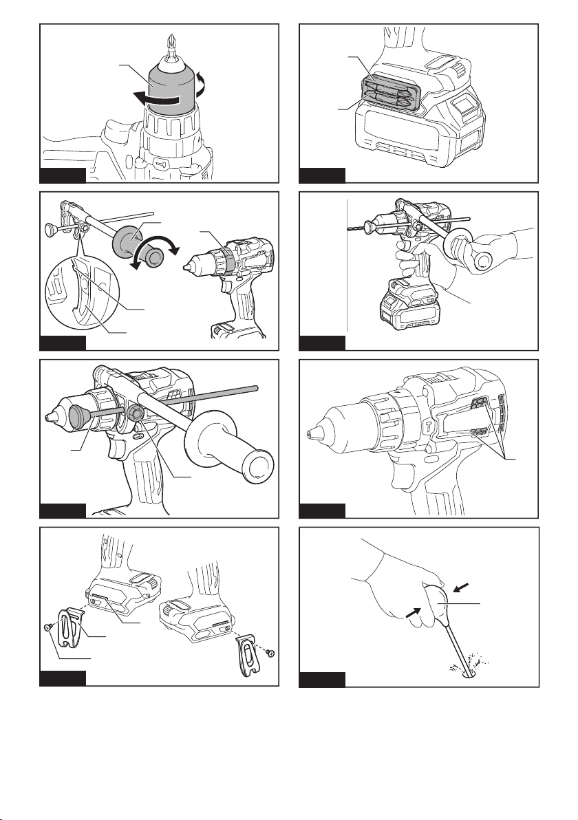
Fig.1: 1. Red indicator 2. Button 3. Battery cartridge
T o remov e the b attery cartridge, slide it from the tool
w hile sliding the b utton on the front of the cartridge.
T o install the b attery cartridge, align the tongue on the
b attery cartridge w ith the groov e in the housing and slip
it into place. Insert it all the w ay until it locks in place
w ith a little click. If y ou can see the red indicator on the
upper side of the b utton, it is not locked completely .
CAUTION: Alw ays install the battery cartridge
fully until the red indicator cannot be seen. If not,
it may accidentally fall out of the tool, causing injury to
y ou or someone around y ou.
CAUTION: Do not install the battery cartridge
forcibly. If the cartridge does not slide in easily , it is
not b eing inserted correctly .

7ENGLISH
Indicating the remaining battery capacity
Press the check b utton on the b attery cartridge to indi-
cate the remaining b attery capacity . T he indicator lamps
light up for a few seconds.
Fig.2: 1. Indicator lamps 2. C heck b utton
Indicator lamps Remaining
capacity
Lighted Off Blinking
7 5 % to 1 0 0 %
5 0 % to 7 5 %
2 5 % to 5 0 %
0 % to 2 5 %
C harge the
b attery .
T he b attery
may hav e
malfunctioned.
NOTE: Depending on the conditions of use and the
amb ient temperature, the indication may differ slightly
from the actual capacity .
Tool / battery protection system
T he tool is eq uipped w ith a tool/ b attery protection sy s-
tem. T his sy stem automatically cuts off pow er to the
motor to ex tend tool and b attery life. T he tool w ill auto-
matically stop during operation if the tool or b attery is
placed under one of the follow ing conditions:
Overload protection
When the tool is operated in a manner that causes it to draw
an ab normally high current, the tool stops automatically . In this
situation, turn the tool off and stop the application that caused
the tool to b ecome ov erloaded. T hen turn the tool on to restart.
Overheat protection
When the tool is ov erheated, the tool stops automati-
cally and the lamp b links. In this situation, let the tool/
b attery cool b efore turning the tool on again.
Overdischarge protection
When the b attery capacity is not enough, the tool stops
automatically . In this case, remov e the b attery from the
tool and charge the b attery .
Sw itch action
Fig.3: 1. S w itch trigger
CAUTION: Before installing the battery car-
tridge into the tool, alw ays check to see that the
sw itch trigger actuates properly and returns to
the " OFF" position w hen released.
T o start the tool, simply pull the sw itch trigger. T ool
speed is increased b y increasing pressure on the sw itch
trigger. Release the sw itch trigger to stop.
NOTE: T he tool automatically stops if y ou keep pull-
ing the sw itch trigger for ab out 6 minutes.
Lighting up the front lamp
Fig.4: 1. Lamp
CAUTION: Do not look in the light or see the
source of light directly.
Pull the sw itch trigger to light up the lamp. T he lamp
keeps on lighting w hile the sw itch trigger is b eing pulled.
T he lamp goes out approx imately 1 0 seconds after
releasing the sw itch trigger.
NOTE: When the tool is ov erheated, the tool stops
automatically and the lamp starts ashing. In this
case, release the sw itch trigger. T he lamp turns off in
one minute.
NOTE: U se a dry cloth to w ipe the dirt off the lens of
the lamp. Be careful not to scratch the lens of lamp, or
it may low er the illumination.
Reversing sw itch action
Fig.5: 1. Rev ersing sw itch lev er
CAUTION: Alw ays check the direction of
rotation before operation.
CAUTION: Use the reversing sw itch only after
the tool comes to a complete stop. C hanging the
direction of rotation b efore the tool stops may dam-
age the tool.
CAUTION: W hen not operating the tool,
alw ays set the reversing sw itch lever to the neu-
tral position.
T his tool has a rev ersing sw itch to change the direction
of rotation. Depress the rev ersing sw itch lev er from the
A side for clockw ise rotation or from the B side for coun-
terclockw ise rotation.
When the rev ersing sw itch lev er is in the neutral posi-
tion, the sw itch trigger cannot b e pulled.
Speed change
Fig.6: 1. S peed change lev er
CAUTION: Alw ays set the speed change lever
fully to the correct position. If y ou operate the
tool w ith the speed change lev er positioned halfw ay
b etw een the " 1 " side and " 2 " side, the tool may b e
damaged.
CAUTION: Do not use the speed change lever
w hile the tool is running. T he tool may b e damaged.
Displayed
Number
Speed Torque Applicable
operation
1Low H igh H eav y load-
ing operation
2H igh Low Light loading
operation

8ENGLISH
To change the speed, switch off the tool rst. Push the
speed change lev er to display " 2 " for high speed or " 1 "
for low speed. Be sure that the speed change lev er is
set to the correct position b efore operation.
If the tool speed is coming dow n ex tremely during the
operation w ith display " 2 " , push the lev er to display " 1 "
and restart the operation.
Selecting the action mode
NOTICE: Alw ay s set the ring correctly to y our
desired mode mark. If y ou operate the tool w ith the
ring positioned halfw ay b etw een the mode marks, the
tool may b e damaged.
NOTICE: Do not change the action mode w hile
rotating.
NOTE: When y ou change the position from " " to
other modes, it may be a little difculty to slide the
action mode changing ring. In this case, sw itch on
and run the tool for a second at the " " position,
then stop the tool and slide the ring to y our desired
position.
Fig.7: 1. Action mode changing ring 2. Mark
3. Arrow
T his tool has three action modes.
• Drilling mode (rotation only )
• H ammer drilling mode (rotation w ith
hammering)
• S crew driv ing mode (rotation w ith clutch)
S elect one mode suitab le for y our w ork. T urn the
action mode changing ring and align the mark that y ou
selected w ith the arrow on the tool b ody .
Adjusting the fastening torque
CAUTION: Make sure that the dial is clean. Depending on the work environment, foreign objects such as iron
scraps or chips may adhere to the dial and cause the personal injury.
Fig.8: 1. Dial 2. Indicator 3. Button 4. Green light
The fastening torque can be adjusted in levels in low speed and levels in high speed.
1. Align marking w ith the arrow on the tool b ody b y turning the action mode changing ring.
2. Pull the sw itch trigger and release it as soon as the indicator turns on.
3. Push the b utton, and the green light b links.
4. Turn the dial, and adjust the torque level while the green light is blinking.
5. Push the b utton to set the v alue.
NOTE: After pushing the button in step , the green light turns off. If you adjust the torque level again, start over
from step 3 .
NOTE: If y ou leav e the green light b linking for a w hile, it stops b linking and the v alue display ed in the indicator w ill
b e set.
NOTE: Y ou can set the fastening torq ue lev el in tw o patterns; high speed and low speed.
When the lev er display s " 1 " , the torq ue lev el in low speed can b e set. When the lev er display s " 2 " , the torq ue lev el
in high speed can b e set.
When y ou change the speed w ith the speed change lev er, the indicator b links three times. After that, driv e a trial
screw to check the speed and torq ue lev el.
NOTE: If y ou pull the sw itch trigger w hile the green light is b linking, the green light turns off and y ou w ill not b e
able to adjust the torque level. To adjust the torque level again, release the switch trigger and turn the dial while the
green light is b linking.
NOTE: If y ou turn the action mode changing ring w hile the green light is b linking, the green light turns off and y ou
will not be able to adjust the torque level. To adjust the torque level again, start over from step .
T o ob tain suitab le torq ue lev el, perform a test driv e w ith a w orkpiece of the same material that y ou are going to
screw .
T he follow ing show s the rough guide of the relationship b etw een the screw size and graduation.
Low speed
Torque level 123456789 10 11 12 13 14 15 16 17 18 19 20 21
Machine screw M4 M5 M6 –
Wood
screw
S oft
w ood
(e.g.
pine)
ø 3 .5
x 2 2
ø 4 .1 x 3 8 –ø 5 .1 x 5 0 –ø 6 .2 x 6 3 –
H ard
w ood
(e.g.
lauan)
–ø 3 .5
x 2 2
ø 4 .1 x 3 8 –ø 5 .1 x 5 0 –ø 6 .2 x 6 3 –

9ENGLISH
Torque level 22 23 24 25 26 27 28 29 30 31 32 33 34 35 36 37 38 39 40 41
Machine screw –
Wood
screw
S oft
w ood
(e.g.
pine)
–ø 9 x 7 5 –ø 1 0 x 9 0 –
H ard
w ood
(e.g.
lauan)
–ø 9 x 7 5 –ø 1 0 x 9 0 –
High speed
Torque level 123456789 10 11 12 13 14 15 16 17 18 19 20 21
Machine screw M4 M5 M6 –
Wood
screw
S oft
w ood
(e.g.
pine)
ø 3 .5
x 2 2
ø 4 .1 x 3 8 –ø 5 .1 x 5 0 –ø 6 .2 x 6 3 –
H ard
w ood
(e.g.
lauan)
–ø 3 .5
x 2 2
ø 4 .1 x 3 8 –ø 5 .1 x 5 0 –ø 6 .2 x 6 3 –
Electronic function
T he tool is eq uipped w ith the electronic functions for
easy operation.
• Activ e Feedb ack sensing T echnology
If the tool is sw ung at the predetermined accelera-
tion during operation, the motor is forcib ly stopped
to reduce the b urden on the w rist.
NOTICE: Hold the tool rmly while operating.
NOTICE: If any malfunction occurred w ith the
electronic function, the light b links for 3 seconds,
and then, turns off. In that case, contact w ith Makita
Authorized or Factory S erv ice C enters to repair.
NOTE: T his function does not w ork if the acceleration
does not reach the predetermined one w hen the tool
is sw ung.
NOTE: If the tool is forcib ly stopped, release the
sw itch trigger, and then pull the sw itch trigger to
restart the tool.
ASSEMBLY
CAUTION: Alw ays be sure that the tool is
sw itched off and the battery cartridge is removed
before carrying out any w ork on the tool.
Installing or removing driver bit/
drill bit
Optional accessory
Fig.9 : 1. S leev e 2. C lose 3. Open
T urn the sleev e counterclockw ise to open the chuck
jaws. Place the driver bit/drill bit in the chuck as far
as it w ill go. T urn the sleev e clockw ise to tighten the
chuck. T o remov e the driv er b it/ drill b it, turn the sleev e
counterclockw ise.
Installing side grip ( auxiliary handle)
Fig.10: 1. S ide grip 2. Protrusion 3. Groov e 4. Arm
Alw ay s use the side grip to ensure operating safety .
Install the side grip so that the protrusions on the arm t
in the groov es on the tool b arrel. T urn the grip clockw ise
to secure it. The grip can be xed at desired angle.
Adjustable depth rod
Fig.11: 1. Depth rod 2. C lamp screw
The adjustable depth rod is used to drill holes of uniform
depth. Loosen the clamp screw , set to desired position,
then tighten the clamp screw .
Installing hook
CAUTION: W hen installing the hook, alw ays
secure it with the screw rmly. If not, the hook
may come off from the tool and result in the personal
injury.
Fig.12: 1. Groov e 2. H ook 3. S crew
T he hook is conv enient for temporarily hanging the tool.
T his can b e installed on either side of the tool. T o install
the hook, insert it into a groov e in the tool housing on
either side and then secure it w ith a screw . T o remov e,
loosen the screw and then take it out.
Installing driver bit holder
Optional accessory
Fig.13: 1. Driv er b it holder 2. Driv er b it
Fit the driv er b it holder into the protrusion at the tool foot
on either right or left side and secure it w ith a screw .
When not using the driv er b it, keep it in the driv er b it
holders. Driv er b its 4 5 mm- long (1 - 3 / 4 " ) can b e kept
there.

10 ENGLISH
OPERATION
Hold the tool rmly with one hand on the grip and the
other hand on the handle to control the tw isting action.
Fig.14
NOTICE: When the speed comes dow n ex tremely ,
reduce the load or stop the tool to av oid the tool
damage.
NOTICE: Do not cov er v ents, or it may cause ov er-
heating and damage to the tool.
Fig.15: 1. Vent
Screw driving operation
NOTICE: Adjust the dial to the proper torque level
for y our w ork.
NOTICE: Make sure that the driv er b it is inserted
straight in the screw head, or the screw and/ or driv er
b it may b e damaged.
First, turn the action mode changing ring so that the
arrow on the tool b ody points to the marking, and
adjust the torque level.
Place the point of the driv er b it in the screw head and
apply pressure to the tool. S tart the tool slow ly and then
increase the speed gradually . Release the sw itch trigger
as soon as the tool stops the rotation automatically and
the green light turns on for 5 seconds.
NOTE: When driv ing w ood screw , pre- drill a pilot hole
2 / 3 the diameter of the screw . It makes driv ing easier
and prev ents splitting of the w orkpiece.
NOTE: In a cold env ironment, the tool may stop at
low er torq ue lev el depending on circumstances.
Hammer drilling operation
CAUTION: There is a tremendous and sud-
den tw isting force exerted on the tool/drill bit
at the time of hole breakthrough, w hen the hole
becomes clogged w ith chips and particles, or
w hen striking reinforcing rods embedded in the
concrete.
First, turn the action mode changing ring so that the
arrow on the tool b ody points to the marking.
Be sure to use a tungsten- carb ide tipped drill b it.
Position the drill b it at the desired location for the hole,
then pull the sw itch trigger. Do not force the tool. Light
pressure giv es b est results. K eep the tool in position
and prev ent it from slipping aw ay from the hole.
Do not apply more pressure w hen the hole b ecomes
clogged w ith chips or particles. Instead, run the tool at
an idle, then remov e the drill b it partially from the hole.
By repeating this sev eral times, the hole w ill b e cleaned
out and normal drilling may b e resumed.
Blow -out bulb
Optional accessory
Fig.16: 1. Blow - out b ulb
After drilling the hole, use the b low - out b ulb to clean the
dust out of the hole.
Drilling operation
First, turn the action mode changing ring so that the
arrow points to the marking. T hen proceed as
follow s.
Drilling in w ood
When drilling in w ood, the b est results are ob tained
w ith w ood drills eq uipped w ith a guide screw . T he guide
screw makes drilling easier b y pulling the drill b it into
the w orkpiece.
Drilling in metal
T o prev ent the drill b it from slipping w hen starting a
hole, make an indentation w ith a center- punch and
hammer at the point to b e drilled. Place the point of the
drill b it in the indentation and start drilling.
U se a cutting lub ricant w hen drilling metals. T he ex cep-
tions are iron and b rass w hich should b e drilled dry .
CAUTION: Pressing excessively on the tool
w ill not speed up the drilling. In fact, this ex cessiv e
pressure w ill only serv e to damage the tip of y our drill
b it, decrease the tool performance and shorten the
serv ice life of the tool.
CAUTION: Hold the tool rmly and exert care
w hen the drill bit begins to break through the
w orkpiece. T here is a tremendous force ex erted on
the tool/ drill b it at the time of hole b reak through.
CAUTION: A stuck drill bit can be removed
simply by setting the reversing sw itch to reverse
rotation in order to back out. How ever, the tool
may back out abruptly if you do not hold it rmly.
CAUTION: Alw ays secure w orkpieces in a
vise or similar hold-dow n device.
CAUTION: If the tool is operated continuously
until the battery cartridge has discharged, allow
the tool to rest for 15 minutes before proceeding
w ith a fresh battery.
MAINTENANCE
CAUTION: Alw ays be sure that the tool is
sw itched off and the battery cartridge is removed
before attempting to perform inspection or
maintenance.
NOTICE: Never use gasoline, benzine, thinner,
alcohol or the like. Discoloration, deformation or
cracks may result.
T o maintain product S AFE T Y and RE LIABILIT Y ,
repairs, any other maintenance or adjustment should
b e performed b y Makita Authorized or Factory S erv ice
C enters, alw ay s using Makita replacement parts.

11 ENGLISH
OPTIONAL
ACCESSORIES
CAUTION: These accessories or attachments
are recommended for use w ith your Makita tool
specied in this manual. T he use of any other
accessories or attachments might present a risk of
injury to persons. Only use accessory or attachment
for its stated purpose.
If y ou need any assistance for more details regard-
ing these accessories, ask y our local Makita S erv ice
C enter.
• Drill b its
• Driv er b its
• T ungsten- carb ide tipped drill b it
• Blow - out b ulb
• Driv er b it holder
• H ook
• Makita genuine b attery and charger
NOTE: S ome items in the list may b e included in the
tool package as standard accessories. T hey may
differ from country to country .

12 FRANÇAIS
FRANÇAIS ( Instructions originales)
SPÉ CIFICATIONS
Modè le : HP001G
C apacité s de perç age Maç onnerie 2 0 mm
Acier 2 0 mm
Bois Mè che hé licoï dale : 5 0 mm
Foret à auto- av ance : 7 6 mm
S cie cloche : 1 5 2 mm
C apacité s de serrage Vis à b ois 1 0 mm x 9 0 mm
Vis mé caniq ue M6
Vitesse à v ide (tr/ min) É lev é e (2 ) 0 - 2 6 0 0 min- 1
Basse (1 ) 0 - 6 5 0 min- 1
Frappes par minute É lev é e (2 ) 0 - 3 9 0 0 0 min- 1
Basse (1 ) 0 - 9 7 5 0 min- 1
Longueur totale 1 8 2 mm
T ension nominale 3 6 V - 4 0 V c.c. max .
Poids net 2 ,7 - 3 ,0 kg
tant donné l’évolution constante de notre programme de recherche et de développement, les spécications
contenues dans ce manuel sont sujettes à modication sans préavis.
Les spécications peuvent varier suivant les pays.
• Le poids peut ê tre diffé rent selon les accessoires, notamment la b atterie. Les associations la plus lé gè re et la
plus lourde, conformé ment à la procé dure E PT A 0 1 / 2 0 1 4 , sont indiq ué es dans le tab leau.
Batterie et chargeur applicables
Batterie BL4 0 2 5 / BL4 0 4 0
C hargeur DC 4 0 RA
•
C ertains chargeurs et b atteries ré pertorié s ci- dessus peuv ent ne pas ê tre disponib les selon la ré gion où v ous ré sidez.
AVERTISSEMENT : N’ utilisez que les batteries et les chargeurs répertoriés ci-dessus. L’ utilisation
d’ autres b atteries et chargeurs peut prov oq uer des b lessures et/ ou un incendie.
Utilisations
L’ outil est conç u pour le perç age av ec percussion dans
la b riq ue, la maç onnerie en b riq ues et la maç onnerie. Il
conv ient aussi pour le v issage et perç age sans percus-
sion dans le b ois, le mé tal, la cé ramiq ue et le plastiq ue.
Bruit
Niv eau de b ruit pondé ré A ty piq ue, dé terminé selon
E N6 2 8 4 1 - 2 - 1 :
Niv eau de pression sonore (LpA) : 8 5 dB (A)
Niv eau de puissance sonore (LWA ) : 9 6 dB (A)
Incertitude (K ) : 3 dB (A)
NOTE : La ou les v aleurs d’ é mission de b ruit dé cla-
ré es ont é té mesuré es conformé ment à la mé thode
de test standard et peuv ent ê tre utilisé es pour com-
parer les outils entre eux .
NOTE : La ou les v aleurs d’ é mission de b ruit dé cla-
ré es peuv ent aussi ê tre utilisé es pour l’ é v aluation
pré liminaire de l’ ex position.
AVERTISSEMENT :
Portez un serre-tê te antibruit.
AVERTISSEMENT :
L’ émission de bruit lors de
l’ usage réel de l’ outil électrique peut ê tre différente de la
ou des valeurs déclarées, suivant la façon dont l’ outil est
utilisé, particuliè rement selon le type de piè ce usinée.
AVERTISSEMENT :
Les mesures de sécurité à
prendre pour protéger l’ utilisateur doivent ê tre basées
sur une estimation de l’ exposition dans des condi-
tions réelles d’ utilisation ( en tenant compte de toutes
les composantes du cycle d’ utilisation, comme par
exemple le moment de sa mise hors tension, lorsqu’ il
tourne à vide et le moment de son déclenchement) .
Vibrations
Valeur totale de v ib rations (somme de v ecteur triax ial)
dé terminé e selon E N6 2 8 4 1 - 2 - 1 :
Mode de trav ail : perç age par percussion dans le b é ton
É mission de v ib rations (ah, ID) : 6 ,0 m/ s2
Incertitude (K ) : 1 ,5 m/ s2
Mode de trav ail : perç age dans le mé tal
É mission de v ib rations (ah,D) : 2 ,5 m/ s2ou moins
Incertitude (K ) : 1 ,5 m/ s2

13 FRANÇAIS
NOTE : La ou les v aleurs de v ib ration totales dé cla-
ré es ont é té mesuré es conformé ment à la mé thode
de test standard et peuv ent ê tre utilisé es pour com-
parer les outils entre eux .
NOTE : La ou les v aleurs de v ib ration totales dé cla-
ré es peuv ent aussi ê tre utilisé es pour l’ é v aluation
pré liminaire de l’ ex position.
AVERTISSEMENT : L’ émission de vibrations
lors de l’ usage réel de l’ outil électrique peut ê tre
différente de la ou des valeurs déclarées, suivant
la façon dont l’ outil est utilisé, particuliè rement
selon le type de piè ce usinée.
AVERTISSEMENT : Les mesures de sécurité
à prendre pour protéger l’ utilisateur doivent ê tre
basées sur une estimation de l’ exposition dans
des conditions réelles d’ utilisation ( en tenant
compte de toutes les composantes du cycle
d’ utilisation, comme par exemple le moment de
sa mise hors tension, lorsqu’ il tourne à vide et le
moment de son déclenchement) .
Déclaration de conformité CE
Pour les pays européens uniquement
La dé claration de conformité C E est fournie en Annex e
A à ce mode d’ emploi.
CONSIGNES DE SÉ CURITÉ
Consignes de sécurité générales
pour outils électriques
AVERTISSEMENT : Veuillez lire les
consignes de sécurité, instructions, illustrations
et spécications qui accompagnent cet outil
électrique. Le non- respect de toutes les instructions
indiq ué es ci- dessous peut entraîner une é lectrocu-
tion, un incendie et/ ou de grav es b lessures.
Conservez toutes les mises en
garde et instructions pour réfé-
rence ultérieure.
Le terme « outil é lectriq ue » dans les av ertissements
fait ré fé rence à l’ outil é lectriq ue alimenté par le secteur
(av ec cordon d’ alimentation) ou à l’ outil é lectriq ue fonc-
tionnant sur b atterie (sans cordon d’ alimentation).
Consignes de sécurité pour perceuse
percussion-visseuse sans l
Consignes de sécurité pour toutes les tâ ches
1 . Portez des protections d’ oreilles lorsque
vous effectuez un perçage avec percussion.
L’ ex position au b ruit peut entraîner la surdité .
2 . Utilisez la ou les poignées auxiliaires. T oute
perte de maîtrise de l’ outil comporte un risq ue de
b lessure.
3 . Tenez l’ outil électrique par des surfaces de
prise isolées lorsque vous effectuez une tâ che
au cours de laquelle l’ accessoire de coupe
ou les éléments de xation peuvent entrer
en contact avec des ls cachés. Le contact de
l’accessoire de coupe ou des éléments de xa-
tion avec un l sous tension peut transmettre du
courant dans les piè ces mé talliq ues ex posé es de
l’ outil é lectriq ue et é lectrocuter l’ utilisateur.
4 . Assurez-vous toujours de travailler en position
stable. Veillez à ce que personne ne se trouve
en dessous de vous quand vous utilisez l’ outil
en hauteur.
5 . Tenez l’ outil fermement.
6 . Gardez les mains éloignées des piè ces en
rotation.
7 . Ne vous éloignez pas en laissant l’ outil tour-
ner. Ne le faites fonctionner que lorsque vous
l’ avez bien en main.
8 .
Ne touchez pas le foret ou la piè ce immédiate-
ment aprè s l’ exécution du travail ; ils peuvent
ê tre extrê mement chauds et vous brû ler la peau.
9 . Certains matériaux contiennent des produits
chimiques qui peuvent ê tre toxiques. Prenez
garde de ne pas avaler la poussiè re et évitez
tout contact avec la peau. Suivez les données
de sécurité du fournisseur du matériau.
10. Si le foret ne peut pas ê tre desserré mê me
en ouvrant la mâ choire, utilisez des pinces
pour l’ extirper. Le b ord tranchant du foret risq ue
de v ous b lesser si v ous essay ez de l’ ex tirper
manuellement.
Consignes de sécurité en cas d’ utilisation de forets
longs
1 . Ne faites jamais fonctionner l’ outil à une
vitesse supérieure à la vitesse nominale maxi-
male du foret. À une v itesse plus é lev é e, le foret
risq ue de se tordre s’ il lui est permis de tourner
lib rement sans toucher la piè ce, ce q ui pré sente
un risq ue de b lessure.
2 . Commencez toujours le perçage à basse
vitesse avec la pointe du foret en contact avec
la piè ce. À une v itesse plus é lev é e, le foret risq ue
de se tordre s’ il lui est permis de tourner lib rement
sans toucher la piè ce, ce q ui pré sente un risq ue
de b lessure.
3 . Appliquez une pression uniquement en ligne
directe avec le foret et n’ exercez pas une pres-
sion excessive. Les forets peuv ent se tordre et
se casser ou prov oq uer la perte de contrô le, ce
q ui pré sente un risq ue de b lessure.
CONSERVEZ CES
INSTRUCTIONS.
AVERTISSEMENT : NE vous laissez PAS
tromper (au l d’une utilisation répétée) par un
sentiment d’ aisance et de familiarité avec le
produit, en négligeant le respect rigoureux des
consignes de sécurité qui accompagnent le pro-
duit en question. La MAUVAISE UTILISATION de
l’ outil ou l’ ignorance des consignes de sécurité
indiquées dans ce mode d’ emploi peut entraî ner
de graves blessures.

14 FRANÇAIS
Consignes de sécurité importantes
pour la batterie
1 . Avant d’ utiliser la batterie, lisez toutes les
instructions et précautions relatives ( 1) au
chargeur de batterie, ( 2) à la batterie, et ( 3) au
produit utilisant la batterie.
2 . Ne désassemblez pas et ne modiez pas la
batterie. C ela pourrait entraîner un incendie, une
chaleur ex cessiv e ou une ex plosion.
3 . Cessez immédiatement l’ utilisation si le temps
de fonctionnement devient excessivement
court. Il y a risque de surchauffe, de brû lures,
voire d’ explosion.
4 . Si l’ électrolyte pénè tre dans vos yeux, rin-
cez-les à l’ eau claire et consultez immédiate-
ment un médecin. Il y a risque de perte de la
vue.
5 . Ne court-circuitez pas la batterie :
(1 ) Ne touchez les bornes avec aucun maté-
riau conducteur.
(2 ) É vitez de ranger la batterie dans un
conteneur avec d’ autres objets métal-
liques, par exemple des clous, des piè ces
de monnaie, etc.
(3 ) N’ exposez pas la batterie à l’ eau ou à la
pluie.
Un court-circuit de la batterie peut provoquer
une intensité de courant élevée, une sur-
chauffe, parfois des brû lures et mê me une
panne.
6 . Ne rangez pas l’ outil et la batterie dans un
endroit où la température risque d’ atteindre ou
de dépasser 50 ° C.
7 . Ne jetez pas la batterie au feu mê me si elle est
sérieusement endommagée ou complè tement
épuisée. La batterie peut exploser au contact
du feu.
8 . Abstenez-vous de clouer, couper, écraser,
jeter, laisser tomber la batterie, ou de la heur-
ter contre un objet dur. C ela pourrait entraîner
un incendie, une chaleur ex cessiv e ou une
ex plosion.
9 . N’ utilisez pas la batterie si elle est
endommagée.
10. Les batteries au lithium-ion contenues sont
soumises aux exigences de la législation sur
les marchandises dangereuses.
Lors du transport commercial par des tierces
parties ou des transitaires par ex emple, des ex i-
gences spéciques en matière d’étiquetage et
d’ emb allage doiv ent ê tre respecté es.
Pour la pré paration de l’ article ex pé dié , il est
né cessaire de consulter un ex pert en maté riau
dangereux . Veuillez é galement respecter les
ré glementations nationales susceptib les d’ ê tre
plus dé taillé es.
Recouv rez les contacts ex posé s av ec du rub an
adhé sif ou du rub an de masq uage et emb allez la
b atterie de telle sorte q u’ elle ne puisse pas b ouger
dans l’ emb allage.
1 1 . Lors de la mise au rebut de la batterie, reti-
rez-la de l’ outil et jetez-la en lieu sû r. Suivez les
réglementations locales en matiè re de mise au
rebut des batteries.
12. Utilisez les batteries uniquement avec les
produits spéciés par Makita. L’ insertion de
b atteries dans des produits non conformes peut
prov oq uer un incendie, une chaleur ex cessiv e,
une ex plosion ou une fuite de l’ é lectroly te.
13. Lorsque vous n’ utilisez pas l’ outil pendant une
période prolongée, la batterie doit ê tre retirée
de l’ outil.
14. Pendant et aprè s l’ utilisation, la batterie peut
chauffer, ce qui peut entraî ner des brû lures, y
compris en cas de température relativement
basse. Manipulez les batteries chaudes avec
précaution.
15. Ne touchez pas la borne de l’ outil immédiate-
ment aprè s utilisation car elle peut ê tre assez
chaude pour provoquer des brû lures.
16. É vitez que des copeaux, de la poussiè re ou
du sol adhè rent aux bornes, aux trous et aux
rainures de la batterie. C ela pourrait ré duire les
performances ou casser l’ outil ou la b atterie.
17. À moins que l’ outil prenne en charge un tel
usage, n’ utilisez pas la batterie à proximité de
lignes électriques haute tension. C ela pourrait
entraîner un dy sfonctionnement ou casser l’ outil
ou la b atterie.
CONSERVEZ CES
INSTRUCTIONS.
ATTENTION : N’ utilisez que des batteries
Makita d’ origine. L’ utilisation de b atteries de marq ue
autre que Makita ou de batteries modiées peut pro-
v oq uer l’ ex plosion des b atteries, ce q ui pré sente un
risq ue d’ incendie, de dommages maté riels et corpo-
rels. C ela annulera é galement la garantie Makita pour
l’ outil et le chargeur Makita.
Conseils pour assurer la durée
de vie optimale de la batterie
1 . Chargez la batterie avant qu’ elle ne soit com-
plè tement déchargée. Arrê tez toujours l’ outil
et rechargez la batterie quand vous remarquez
que la puissance de l’ outil diminue.
2 . Ne rechargez jamais une batterie complè te-
ment chargée. La surcharge réduit la durée de
service de la batterie.
3 . Chargez la batterie à une température
ambiante comprise entre 10 ° C et 40 ° C. Avant
de charger une batterie chaude, laissez-la
refroidir.
4 . Lorsque vous n’ utilisez pas la batterie, reti-
rez-la de l’ outil ou du chargeur.
5 . Rechargez la batterie si elle est restée inutili-
sée pendant une période prolongée ( plus de
six mois) .

15 FRANÇAIS
DESCRIPTION DU
FONCTIONNEMENT
ATTENTION : Assurez-vous toujours que
l’ outil est hors tension et que sa batterie est
retirée avant de l’ajuster ou de vérier son
fonctionnement.
Insertion ou retrait de la batterie
ATTENTION : É teignez toujours l’ outil avant
de mettre en place ou de retirer la batterie.
ATTENTION :
Tenez fermement l’ outil et la batte-
rie lors de la mise en place ou du retrait de la batterie. S i
v ous ne tenez pas fermement l’ outil et la b atterie, ils peuv ent
v ous glisser des mains, et s’ ab îmer ou v ous b lesser.
Fig.1: 1. Voy ant rouge 2. Bouton 3. Batterie
Pour retirer la b atterie, faites- la glisser hors de l’ outil
tout en faisant glisser le b outon à l’ av ant de la b atterie.
Pour mettre en place la b atterie, alignez la languette sur la
b atterie av ec la rainure sur le compartiment et insé rez- la.
Insérez-la à fond jusqu’à ce qu’un léger déclic se fasse
entendre. S i le v oy ant rouge sur le dessus du b outon est
visible, cela signie qu’elle n’est pas bien verrouillée.
ATTENTION :
Insérez toujours complè tement la
batterie jusqu’ à ce que le voyant rouge ne soit plus visible.
S inon, elle pourrait tomb er accidentellement de l’ outil, au risq ue
de v ous b lesser ou de b lesser q uelq u’ un se trouv ant prè s de v ous.
ATTENTION : N’ insérez pas la batterie de
force. S i elle ne glisse pas facilement, c’ est q ue v ous
ne l’ insé rez pas correctement.
Indication de la charge restante de la batterie
Appuyez sur le bouton de vérication sur la batterie
pour indiq uer la charge restante de la b atterie. Les
té moins s’ allument pendant q uelq ues secondes.
Fig.2: 1. T é moins 2. Bouton de vérication
Témoins Charge
restante
Allumé É teint Clignotant
7 5 % à 1 0 0 %
5 0 % à 7 5 %
2 5 % à 5 0 %
0 % à 2 5 %
C hargez la
b atterie.
Anomalie
possib le
de la b atterie.
NOTE : S elon les conditions d’ utilisation et la tem-
pé rature amb iante, l’ indication peut ê tre lé gè rement
diffé rente de la capacité ré elle.
Systè me de protection de l’ outil/la batterie
L’ outil est é q uipé d’ un sy stè me de protection de l’ outil/ la b atte-
rie. C e sy stè me coupe automatiq uement l’ alimentation v ers le
moteur pour prolonger la duré e de v ie de l’ outil et de la b atte-
rie. S i l’ outil ou la b atterie se trouv e dans l’ une des situations
suiv antes, l’ outil cessera automatiq uement de fonctionner.
Protection contre la surcharge
Lorsq ue l’ outil est utilisé d’ une maniè re prov oq uant un appel de
courant anormalement é lev é , il s’ arrê te automatiq uement. Dans
ce cas, é teignez l’ outil et arrê tez la tâ che ay ant prov oq ué la
surcharge de l’ outil. Puis rallumez l’ outil pour reprendre la tâ che.
Protection contre la surchauffe
E n cas de surchauffe de l’ outil, il s’ arrê te automatiq ue-
ment et la lampe clignote. Dans ce cas, laissez l’ outil ou
la b atterie refroidir av ant de rallumer l’ outil.
Protection contre la décharge totale
de la batterie
Lorsque la charge de la batterie est insufsante, l’outil
s’ arrê te automatiq uement. Dans ce cas, retirez la b atte-
rie de l’ outil et chargez- la.
Fonctionnement de la gâ chette
Fig.3: 1. Gâ chette
ATTENTION : Avant d’ insérer la batterie dans
l’outil, vériez toujours que la gâchette fonc-
tionne bien et revient en position d’ arrê t lorsque
vous la relâ chez.
Il suft d’enclencher la gchette pour démarrer l’outil. La vitesse
de l’ outil augmente à mesure q ue l’ on accroît la pression ex er-
cé e sur la gâ chette. Pour l’ arrê ter, relâ chez la gâ chette.
NOTE : L’ outil s’ arrê tera automatiq uement si v ous
continuez d’ enclencher la gâ chette pendant 6
minutes env iron.
Allumage de la lampe avant
Fig.4: 1. Lampe
ATTENTION : É vitez de regarder directement
le faisceau lumineux ou sa source.
E nclenchez la gâ chette pour allumer la lampe. La lampe
reste allumé e tant q ue la gâ chette est enclenché e. La lampe
s’ é teint env iron 1 0 secondes aprè s av oir relâ ché la gâ chette.
NOTE : E n cas de surchauffe de l’ outil, celui- ci s’ ar-
rê te automatiq uement et la lampe se met à clignoter.
Dans ce cas, relâ chez la gâ chette. La lampe s’ é teint
au b out d’ une minute.
NOTE : Retirez la saleté sur la lentille de la lampe
avec un chiffon sec. Prenez soin de ne pas éraer
la lentille de la lampe sous peine de diminuer son
é clairage.

16 FRANÇAIS
Fonctionnement de l’ inverseur
Fig.5: 1. Lev ier de l’ inv erseur
ATTENTION : Vériez toujours le sens de
rotation avant d’ utiliser l’ outil.
ATTENTION :
N’ utilisez l’ inverseur qu’ une fois que
l’ outil est complè tement arrê té. S i v ous changez le sens de
rotation av ant l’ arrê t de l’ outil, v ous risq uez de l’ endommager.
ATTENTION :
Lorsque vous n’ utilisez pas l’ outil,
placez toujours le levier de l’ inverseur en position neutre.
L’ outil possè de un inv erseur q ui permet de changer le sens de
rotation. E nfoncez le lev ier de l’ inv erseur du cô té A pour une rota-
tion dans le sens des aiguilles d’ une montre, ou du cô té B pour
une rotation dans le sens inv erse des aiguilles d’ une montre.
La gâ chette ne peut pas ê tre enclenché e lorsq ue le
lev ier de l’ inv erseur se trouv e en position neutre.
Changement de vitesse
Fig.6: 1. Lev ier de changement de v itesse
ATTENTION :
Mettez toujours le levier de change-
ment de vitesse parfaitement sur la bonne position. E n
utilisant l’ outil av ec le lev ier de changement de v itesse placé
entre les cô té s « 1 » et « 2 » , v ous risq ueriez d’ ab îmer l’ outil.
ATTENTION : Ne déplacez pas le levier de
changement de vitesse pendant que l’ outil tourne.
Vous risq ueriez d’ ab îmer l’ outil.
Numéro afché
Vitesse Couple
Tâ che applicable
1Faib le É lev é Tche difcile
2É lev é e Faib le T â che facile
Pour changer de v itesse, mettez d’ ab ord l’ outil hors tension.
Enfoncez le levier de changement de vitesse pour afcher
2 » pour une grande v itesse ou « 1 » pour une b asse v itesse.
Av ant d’ utiliser l’ outil, assurez- v ous q ue le lev ier de change-
ment de v itesse se trouv e sur la b onne position.
S i la v itesse de l’ outil diminue considé rab lement pen-
dant la tche avec l’afchage , enfoncez le levier
pour afcher et recommencez.
Sélection du mode de fonctionnement
REMARQUE : Mettez toujours la bague parfaite-
ment sur le sy mb ole du mode dé siré . Vous risq uez
d’ ab îmer l’ outil si v ous l’ utilisez alors q ue la b ague se
trouv e entre deux sy mb oles de mode.
REMARQUE : Ne changez pas le mode d’ action
pendant la rotation.
NOTE :
Lorsq ue v ous changez la position de « »
à un autre mode, il peut s’avérer un peu difcile de
faire glisser la b ague de changement de mode. Le cas
é ché ant, mettez l’ outil sous tension et faites- le tourner
pendant une seconde en position « » , puis arrê tez
l’ outil et faites glisser la b ague sur la position dé siré e.
Fig.7: 1. Bague de changement de mode 2. Repè re
3. Flè che
C et outil offre trois modes de fonctionnement.
• Mode de perç age (rotation uniq uement)
• Mode de perç age av ec percussion (rotation
av ec percussion)
• Mode de v issage (rotation av ec engrenage)
S é lectionnez le mode conv enant à v otre tâ che. T ournez
la b ague de changement de mode et alignez le repè re
que vous avez sélectionné sur la èche de l’outil.
Réglage du couple de serrage
ATTENTION : Assurez- v ous q ue la molette est propre. E n fonction de l’ env ironnement de trav ail, des corps
é trangers comme de la ferraille ou des copeaux peuv ent adhé rer à la molette et prov oq uer des b lessures.
Fig.8: 1. Molette 2. T é moin 3. Bouton 4. Voy ant v ert
Le couple de serrage peut ê tre ré glé selon 4 1 niv eaux à b asse v itesse et 2 1 niv eaux à grande v itesse.
1. Alignez le sy mb ole avec la èche sur le corps de l’outil en tournant la bague de changement de mode.
2. E nclenchez la gâ chette et relâ chez- la dè s q ue le té moin s’ allume.
3. E nfoncez le b outon, et le v oy ant v ert clignote.
4. T ournez la molette, et ré glez le niv eau du couple pendant q ue le v oy ant v ert clignote.
5. E nfoncez le b outon pour ré gler la v aleur.
NOTE : Aprè s av oir enfoncé le b outon à l’ é tape 5 , le v oy ant v ert s’ é teint. S i v ous ré glez à nouv eau le niv eau du
couple, recommencez à partir de l’ é tape 3 .
NOTE :
Si vous laissez le voyant vert clignoter pendant un certain temps, il cesse de clignoter et la valeur afchée sur le témoin sera réglée.
NOTE : Vous pouv ez ré gler le niv eau du couple de serrage selon deux sché mas : grande v itesse et b asse v itesse.
Lorsque le levier afche , le niveau du couple à basse vitesse peut tre réglé. Lorsque le levier afche ,
le niv eau du couple à grande v itesse peut ê tre ré glé .
Lorsque vous modiez la vitesse avec le levier de changement de vitesse, le témoin clignote trois fois. Après cela,
faites un essai de vissage pour vérier la vitesse et le niveau du couple.
NOTE :
Si vous enclenchez la gchette alors que le voyant vert clignote, il s’éteint et vous ne serez pas en mesure d’ajuster le niveau
du couple. Pour ré gler à nouv eau le niv eau du couple, relâ chez la gâ chette et tournez la molette alors q ue le v oy ant v ert clignote.
NOTE :
S i v ous tournez la b ague de changement de mode alors q ue le v oy ant v ert clignote, il s’ é teint et v ous ne serez pas
en mesure d’ajuster le niveau du couple. Pour régler à nouveau le niveau du couple, recommencez à partir de l’étape .

17 FRANÇAIS
Pour ob tenir un niv eau de couple adé q uat, faites un v issage d’ essai av ec une piè ce du mê me maté riau q ue celle
q ue v ous v isserez.
Vous trouv erez ci- dessous une indication approx imativ e de la relation entre la taille de v is et la graduation.
Basse vitesse
Niveau du couple 123456789 10 11 12 13 14 15 16 17 18 19 20 21
Vis mé caniq ue M4 M5 M6 –
Vis à
b ois
Bois
mou
(comme
le pin)
ø 3 ,5
x 2 2
ø 4 ,1 x 3 8 –ø 5 ,1 x 5 0 –ø 6 ,2 x 6 3 –
Bois
franc
(comme
le
mé ranti)
–ø 3 ,5
x 2 2
ø 4 ,1 x 3 8 –ø 5 ,1 x 5 0 –ø 6 ,2 x 6 3 –
Niveau du couple 22 23 24 25 26 27 28 29 30 31 32 33 34 35 36 37 38 39 40 41
Vis mé caniq ue –
Vis à
b ois
Bois
mou
(comme
le pin)
–ø 9 x 7 5 –ø 1 0 x 9 0 –
Bois
franc
(comme
le
mé ranti)
–ø 9 x 7 5 –ø 1 0 x 9 0 –
Grande vitesse
Niveau du couple 123456789 10 11 12 13 14 15 16 17 18 19 20 21
Vis mé caniq ue M4 M5 M6 –
Vis à
b ois
Bois
mou
(comme
le pin)
ø 3 ,5
x 2 2
ø 4 ,1 x 3 8 –ø 5 ,1 x 5 0 –ø 6 ,2 x 6 3 –
Bois
franc
(comme
le
mé ranti)
–ø 3 ,5
x 2 2
ø 4 ,1 x 3 8 –ø 5 ,1 x 5 0 –ø 6 ,2 x 6 3 –
Fonction électronique
L’ outil est doté de fonctions é lectroniq ues pour en facili-
ter le fonctionnement.
• T echnologie de dé tection de ré action activ e
S i l’ outil est animé d’ un mouv ement oscillant à
l’ accé lé ration pré dé terminé e pendant le fonc-
tionnement, le moteur sera forcé à s’ arrê ter pour
ré duire la charge sur le poignet.
REMARQUE : T enez l’ outil fermement pendant q ue
v ous l’ utilisez.
REMARQUE : S i un dy sfonctionnement se produit
av ec la fonction é lectroniq ue, le v oy ant clignote pen-
dant 3 secondes, puis s’ é teint. Dans ce cas, sollicitez
une ré paration à un centre de serv ice aprè s- v ente
Makita agré é ou un centre de serv ice usine.
NOTE : C ette fonction est inopé rante si l’ accé lé ration
n’ atteint pas celle pré dé terminé e lors du mouv ement
oscillant de l’ outil.
NOTE : S i l’ outil est arrê té de force, relâ chez la
gâ chette, puis enclenchez- la à nouv eau pour redé -
marrer l’ outil.
ASSEMBLAGE
ATTENTION : Assurez-vous toujours que
l’ outil est hors tension et que sa batterie est reti-
rée avant d’ effectuer toute tâ che dessus.
Installation ou retrait de l’ embout de
vissage/foret
Accessoire en option
Fig.9 : 1. Manchon 2. Fermer 3. Ouv rir
T ournez le manchon dans le sens contraire des aiguilles
d’ une montre pour ouv rir les mâ choires du mandrin.
Insé rez l’ emb out de v issage/ foret à fond dans le man-
drin. T ournez le manchon dans le sens des aiguilles
d’ une montre pour serrer le mandrin. Pour retirer l’ em-
b out de v issage/ foret, tournez le manchon dans le sens
contraire des aiguilles d’ une montre.

18 FRANÇAIS
Pose de la poignée latérale ( poignée
auxiliaire)
Fig.10: 1. Poigné e laté rale 2. Partie saillante
3. Rainure 4. Bras
Utilisez toujours la poignée latérale pour assurer votre sécurité.
Installez la poigné e laté rale de sorte q ue les parties
saillantes sur le b ras pé nè trent dans les rainures du
b arillet de l’ outil. T ournez la poigné e dans le sens des
aiguilles d’ une montre pour la serrer en place. La poi-
gnée peut tre xée à l’angle souhaité.
Tige de profondeur réglable
Fig.11: 1. T ige de profondeur 2. Vis de serrage
La tige de profondeur ré glab le est utile pour percer des
trous de mê me profondeur. Desserrez la v is de serrage,
ré glez- la à la position souhaité e, puis serrez- la.
Installation du crochet
ATTENTION : Lorsque vous installez le cro-
chet, xez-le toujours en place fermement avec la
vis. S inon, le crochet pourrait se dé tacher de l’ outil et
v ous b lesser.
Fig.12: 1. Rainure 2. C rochet 3. Vis
L’ outil est é q uipé d’ un crochet pratiq ue q ui permet
de l’ accrocher temporairement. C e crochet s’ installe
d’ un cô té comme de l’ autre de l’ outil. Pour installer le
crochet, insé rez- le dans une des rainures situé es de
chaq ue cô té du carter de l’ outil, puis serrez- le av ec une
v is. Pour l’ enlev er, desserrez la v is et retirez- le.
Installation du support d’ embout de
vissage
Accessoire en option
Fig.13: 1. S upport d’ emb out de v issage 2. E mb out
de v issage
Mettez le support d’ emb out de v issage dans la partie
saillante du pied de l’ outil, d’ un cô té ou de l’ autre, et
xez-le à l’aide d’une vis.
Lorsq ue v ous n’ utilisez pas l’ emb out de v issage, ran-
gez- le dans un des supports d’ emb out de v issage. Ils
peuv ent contenir des emb outs de v issage d’ une lon-
gueur de 4 5 mm.
UTILISATION
T enez l’ outil fermement en le saisissant d’ une main par
la poigné e laté rale et de l’ autre par la poigné e aux iliaire,
an de résister à la force de torsion.
Fig.14
REMARQUE : Lorsq ue la v itesse diminue considé -
rab lement, ré duisez la charge ou arrê tez l’ outil pour
é v iter de l’ ab îmer.
REMARQUE : Ne couvrez pas les orices
d’ aé ration, car l’ outil pourrait surchauffer ou ê tre
endommagé .
Fig.15: 1. Orice d’aération
Vissage
REMARQUE : Ré glez la molette sur un niv eau de
couple de serrage adapté au trav ail à effectuer.
REMARQUE : Assurez- v ous q ue l’ emb out de v is-
sage est insé ré b ien droit dans la tê te de v is, sinon
v ous risq uerez d’ ab îmer la v is et/ ou l’ emb out de
v issage.
T ournez d’ ab ord la b ague de changement de mode,
de sorte que la èche sur l’outil pointe sur le sym-
b ole et ré glez le niv eau du couple.
Placez la pointe de l’ emb out de v issage dans la tê te de
v is et appliq uez une pression sur l’ outil. Faites dé marrer
l’ outil lentement, puis augmentez la v itesse graduel-
lement. Relâ chez la gâ chette dè s q ue l’ outil cesse de
tourner automatiq uement et q ue le v oy ant v ert s’ allume
pendant 5 secondes.
NOTE : Lorsq ue v ous insé rez une v is à b ois, percez
d’ ab ord un av ant- trou d’ un diamè tre du 2 / 3 de celui
de la v is. C ela facilitera le v issage et é v itera q ue la
piè ce ne se fende.
NOTE : Dans un env ironnement froid, l’ outil peut
s’ arrê ter à un niv eau de couple infé rieur selon les
circonstances.
Perçage avec percussion
ATTENTION : Une trè s grande force de tor-
sion s’ exerce soudainement sur l’ outil/foret lors-
qu’ il émerge sur la face opposée, lorsque le trou
est bouché par des copeaux ou particules ou lors
du contact avec des armatures dans le béton.
T ournez d’ ab ord la b ague de changement de mode, de
sorte que la èche sur l’outil pointe sur le symbole .
Vous dev ez utiliser un foret à pointe de carb ure de
tungstè ne.
Placez le foret à l’ emplacement dé siré pour percer le
trou, puis enclenchez la gâ chette. Ne forcez pas l’ outil.
Vous ob tiendrez de meilleurs ré sultats av ec une lé gè re
pression. Gardez l’ outil en position et empê chez- le de
glisser hors du trou.
N’ appliq uez pas plus de pression lorsq ue le trou est
b ouché par des copeaux ou particules. Laissez plutô t
l’ outil tourner au ralenti et retirez partiellement le foret
du trou. E n ré pé tant cette opé ration plusieurs fois, le
trou se dé b ouchera et v ous pourrez reprendre le per-
ç age normalement.
Poire soufante
Accessoire en option
Fig.16: 1. Poire soufante
Une fois le trou percé, utilisez la poire soufante pour
en retirer les poussiè res.

19 FRANÇAIS
Perçage
T ournez d’ ab ord la b ague de changement de mode, de
sorte que la èche pointe sur le symbole . Procé dez
ensuite comme suit.
Perçage dans le bois
Lorsq ue v ous percez dans le b ois, v ous ob tiendrez un
ré sultat optimal av ec un foret à b ois é q uipé d’ une v is de
guidage. La v is de guidage facilite le perç age en entraî-
nant le foret dans la piè ce.
Perçage dans le métal
Pour q ue le foret ne glisse pas q uand v ous commencez
à percer le trou, faites une entaille à l’ aide d’ un pointeau
et d’ un marteau à l’ emplacement pré v u pour le trou.
Placez la pointe du foret dans l’ entaille et commencez
à percer.
Utilisez un lubriant de coupe pour percer les métaux.
S euls le fer et le laiton doiv ent ê tre percé s à sec.
ATTENTION : Une pression excessive sur
l’ outil n’ accélè rera pas le perçage. E n fait, la pres-
sion ex cessiv e ab îmera la pointe du foret, prov oq uera
une b aisse de rendement de l’ outil et ré duira sa duré e
de serv ice.
ATTENTION : Tenez l’ outil fermement et
redoublez d’ attention lorsque le foret commence
à sortir par la face opposée de la piè ce. U ne trè s
grande force s’ ex erce sur l’ outil/ foret lorsq ue celui- ci
é merge sur la face opposé e.
ATTENTION : Un foret coincé peut ê tre retiré
en réglant simplement l’ inverseur sur la rotation
inverse pour faire marche arriè re. L’ outil peut tou-
tefois faire brusquement marche arriè re si vous
ne le tenez pas fermement.
ATTENTION : Immobilisez toujours les piè ces
à travailler dans un étau ou un dispositif de rete-
nue similaire.
ATTENTION : Si l’ outil est utilisé de maniè re
continue jusqu’ à ce que la batterie se décharge,
laissez-le reposer 15 minutes avant de poursuivre
le travail avec une batterie fraî chement chargée.
ENTRETIEN
ATTENTION : Assurez-vous toujours que
l’ outil est hors tension et que la batterie est reti-
rée avant d’ y effectuer tout travail d’ inspection ou
d’ entretien.
REMARQUE : N’ utilisez jamais d’ essence, ben-
zine, diluant, alcool ou autre produit similaire.
Cela risquerait de provoquer la décoloration, la
déformation ou la ssuration de l’outil.
Pour assurer la S É C U RIT É et la FIABILIT É du produit,
toute ré paration, tout trav ail d’ entretien ou de ré glage
doiv ent ê tre effectué s par un centre d’ entretien Makita
agré é , av ec des piè ces de rechange Makita.
ACCESSOIRES EN
OPTION
ATTENTION : Ces accessoires ou piè ces
complémentaires sont recommandés pour l’ utili-
sation avec l’outil Makita spécié dans ce mode
d’ emploi. L’ utilisation de tout autre accessoire ou
piè ce complé mentaire peut comporter un risq ue de
b lessure. N’ utilisez les accessoires ou piè ces complé -
mentaires qu’aux ns auxquelles ils ont été conçus.
Pour ob tenir plus de dé tails sur ces accessoires,
contactez v otre centre d’ entretien local Makita.
• Forets
• E mb outs de v issage
• Foret à pointe de carb ure de tungstè ne
Poire soufante
• S upport d’ emb out de v issage
• C rochet
• Batterie et chargeur Makita d’ origine
NOTE : Il se peut q ue certains é lé ments de la liste
soient compris dans l’ emb allage de l’ outil en tant
q u’ accessoires standard. Ils peuv ent v arier d’ un pay s
à l’ autre.

20 DEUTSCH
DEUTSCH ( Original-Anleitung)
TECHNISCHE DATEN
Modell: HP001G
Bohrkapazitäten Mauerw erk 2 0 mm
S tahl 2 0 mm
H olz S chlangenb ohrer: 5 0 mm
S elf- Feed- Bohrer: 7 6 mm
Lochsäge: 1 5 2 mm
Anzugskapazitäten H olzschraub e 1 0 mm x 9 0 mm
Maschinenschraub e M6
Leerlaufdrehzahl (U / min) H och (2 ) 0 - 2 .6 0 0 min- 1
Niedrig (1 ) 0 - 6 5 0 min- 1
S chlagzahl pro Minute H och (2 ) 0 - 3 9 .0 0 0 min- 1
Niedrig (1 ) 0 - 9 .7 5 0 min- 1
Gesamtlänge 1 8 2 mm
Nennspannung 3 6 V Gleichstrom - 4 0 V max .
Nettogew icht 2 ,7 - 3 ,0 kg
• Wir b ehalten uns v or, Ä nderungen der technischen Daten im Zuge der E ntw icklung und des technischen
Fortschritts ohne v orherige Ankü ndigung v orzunehmen.
• Die technischen Daten können v on Land zu Land unterschiedlich sein.
•
Das Gew icht kann ab hängig v on dem Aufsatz (den Aufsätzen), einschließ lich des Akkus, unterschiedlich sein. Die
leichteste und die schw erste K omb ination, gemäß dem E PT A- Verfahren 0 1 / 2 0 1 4 , sind in der T ab elle angegeb en.
Zutreffende Akkus und Ladegeräte
Akku BL4 0 2 5 / BL4 0 4 0
Ladegerät DC 4 0 RA
Einige der oben aufgelisteten Akkus und Ladegeräte sind je nach Ihrem Wohngebiet eventuell nicht erhältlich.
WARNUNG: Verw enden Sie nur die oben aufgeführten Akkus und Ladegeräte. Bei Verw endung irgend-
w elcher anderer Akkus und Ladegeräte b esteht Verletzungs- und/ oder Brandgefahr.
Vorgesehene Verw endung
Das Werkzeug ist fü r S chlagb ohren in Ziegeln,
Ziegelw erk und Mauerw erk v orgesehen. E s eignet sich
auch fü r S chraub b etrieb und normales Bohren in H olz,
Metall, K eramik und K unststoff.
Geräusch
T y pischer A- b ew erteter Geräuschpegel ermittelt gemäß
EN62841-2-1:
S challdruckpegel (LpA): 8 5 dB (A)
S challleistungspegel (LWA): 9 6 dB (A)
Messunsicherheit (K ): 3 dB (A)
HINW EIS: Der (Die) angegeb ene(n)
S challemissionsw ert(e) w urde(n) im E inklang mit der
S tandardprü fmethode gemessen und kann (können)
fü r den Vergleich zw ischen Werkzeugen herangezo-
gen w erden.
HINW EIS: Der (Die) angegeb ene(n)
S challemissionsw ert(e) kann (können) auch fü r eine
Vorb ew ertung des Gefährdungsgrads v erw endet
w erden.
WARNUNG: Einen Gehörschutz tragen.
WARNUNG:
Die Schallemission w ährend der
tatsächlichen Benutzung des Elektrow erkzeugs kann
je nach der Benutzungsw eise des W erkzeugs, und
speziell je nach der Art des bearbeiteten W erkstücks,
von dem ( den) angegebenen W ert( en) abw eichen.
WARNUNG:
Identizieren Sie
Sicherheitsmaß nahmen zum Schutz des Benutzers anhand
einer Schätzung des Gefährdungsgrads unter den tatsäch-
lichen Benutzungsbedingungen ( unter Berücksichtigung
aller Phasen des Arbeitszyklus, w ie z. B. Ausschalt- und
Leerlaufzeiten des W erkzeugs zusätzlich zur Betriebszeit) .
Schw ingungen
S chw ingungsgesamtw ert (Drei- Achsen- Vektorsumme)
ermittelt gemäß E N6 2 8 4 1 - 2 - 1 :
Arb eitsmodus: S chlagb ohren in Beton
S chw ingungsemission (ah, ID): 6 ,0 m/ s2
Messunsicherheit (K ): 1 ,5 m/ s2
Arb eitsmodus: Bohren in Metall
S chw ingungsemission (ah,D): 2 ,5 m/ s2oder w eniger
Messunsicherheit (K ): 1 ,5 m/ s2
Other manuals for HP001G
4
Table of contents
Languages:
Other Makita Drill manuals

Makita
Makita DS4010 User manual

Makita
Makita DF0300 User manual

Makita
Makita MDP204 User manual

Makita
Makita 8406C User manual

Makita
Makita DDF453SYE User manual

Makita
Makita HP2032 User manual

Makita
Makita DHP481 User manual

Makita
Makita HP002G User manual

Makita
Makita DDF489Z User manual

Makita
Makita 6073D User manual

Makita
Makita 6233DWAE User manual

Makita
Makita HR2811F Quick start guide

Makita
Makita DA3010 User manual

Makita
Makita 6018D User manual

Makita
Makita Maktec MT622 Manual

Makita
Makita XPH14 User manual

Makita
Makita 6095 User manual

Makita
Makita 6305 User manual

Makita
Makita BDF440 User manual

Makita
Makita 6222D User manual