Makita HP332D Manual

CONCEPT AND MAIN APPLICATIONS
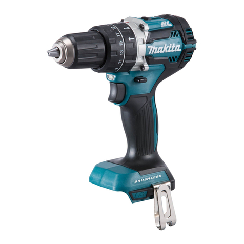
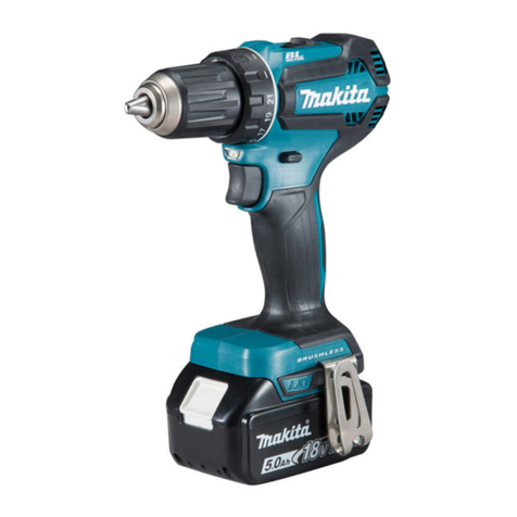
Model HP332D is a Cordless hammer driver drill powered by 10.8V (12V max*4)
slide Li-ion battery.
• More compact and more work amount compared with the current model
HP330D thanks to the newly developed brushless motor and newly
developed 10.8V (12V max*4) slide Li-ion battery
• Best possible ergonomic handle for drilling/driving applications
S
Model HP332D
Battery
Voltage: V 10.8
Capacity: Ah 1.5, 2.0, 4.0
Energy capacity: Wh 17, 22, 44
Cell Li-ion
Type Slide
Charging time (approx): min 50, 70, 130 with DC10WC*3; DC10WD*4
22, 30, 60 with DC10SA*3; DC10SB*4
Max output power (W) 250
No load speed: min-1= rpm 2nd (High) 0-1,500
1st (Low) 0-450
Impacts per minute:
min-1= ipm
2nd (High) 0-22,500
1st (Low) 0-6,750
Capacity of drill chuck: mm (") 0.8 (1/32) - 10 (3/8)
Capacity: mm (")
Masonry 8 (5/16)
Steel 10 (3/8)
Wood 28 (1-1/8)
Torque setting 20 stages + drill mode
Clutch torque setting: N·m (in·lbs) 1.0 (9) - 5.0 (44)
Max tightening
torque: N·m (in·lbs)
Hard joint 35 (310)
Soft joint 21 (190)
Max lock torque: N·m (in·lbs) 32 (280)
Electric brake Yes
Mechanical speed control Yes (2-speed)
Variable speed control Yes (by trigger)
Reversing switch Yes
LED job light Yes
Weight according to
EPTA-Procedure 01/ ver.2.1: kg (lbs) 1.1 (2.4)*1 or 1.3 (2.8)*2
*3 For all countries except North, Central and South American countries, Asia, Australia
*4 For North, Central and South American countries, Asia, Australia
Dimensions: mm ( " )
Length (L) 168 (6-5/8)
Width (W) 66 (2-5/8)
Height (H) 217 (8-1/2)*1 or
236 (9-1/4)*2
L
W
H
*1 With battery BL1015; BL1020B
*2 With battery BL1040B
TECHNICAL INFORMATION
PRODUCT
P 1/ 20
Model No.
Description Cordless Hammer Driver Drill
HP332D December 2015
OFFICIAL USE
for ASC & Sales Shop

P 2/ 20
Battery*1
Charger*1
Battery cover*2
Belt clip
Phillips bit 2-45 (for N-type areas) or 2-50 (for M-type areas)
Plastic carrying case*1
*1 Battery and Charger are not supplied with “Z” model.
*2 Supplied with the same quantity of extra Battery.
Note: The standard equipment may vary by country or model variation.
*3 For all countries except North, Central and South American countries, Asia, Australia
*4 For North, Central and South American countries, Asia, Australia
Battery BL1015*3; BL1016*4
Battery BL1020B*3; BL1021B*4
Battery BL1040B*3; BL1041B*4
Charger DC10SA*3; DC10SB*4
Charger DC10WC*3; DC10WD*4
Driver bits
Socket bits
Belt clip
Bit holder
Holster
Standard equipment
Optional accessories

P 3/ 20
Repair
CAUTION: Remove the battery and the bit from the machine for safety before
repair/ maintenance in accordance with the instruction manual!
[1] NECESSARY REPAIRING TOOLS
Code No. Description Use for
1R003
1R038
1R212-A
1R212-B
A-43240 Socket 19-52
[2] LUBRICATION
Fig. 1
Item No. Description AmountPortion to lubricate
RETAINING RING PLIERS ST-2N Removing / Mounting Ring spring 10 (for DF032D)
ARMATURE HOLDER 32 SET Holding Socket 19-52, when removing Drill chuck
TIP FOR RETAINING RING PLIERS Attaching to 1R003 in order to remove / to mount Ring spring 10
(for DF032D)
1/4" HEX.SHANK BIT FOR M8
Hex wrench 8
Bit adapter
Nut spinner handle 12.7 mm
< Note >
If it is compelled to disassemble Gear assembly in the step of replacement of Drill chuck,
lubricate gears, as need arises. However, in case of trouble on Gears, replace Gear assembly
as an assembly parts.
PLATE SET (WITH SCREWS)
1R231 Removing drill chuck (for DF332D, HP332D)
Removing drill chuck (for DF332D, HP332D)
Removing / Mounting drill chuck (for DF332D, HP332D)
Apply Makita grease FANo.2 to the portions designated with the black triangle.
(a)
(b)
(b)
(a)
Ring gear 44
Ring gear 40
Rear housing
Ring gear 44 Spur gear 17-40
complete
(e)
(d) Spur gear 17-40 complete
(d)
(e)
(c)
Spur gear 13 complete
Spur gear 15
Spur gear 11 Teeth portion
Teeth portion
Teeth portion
Teeth portion
a little
a little
a little
a little
(c)
Index
[1] NECESSARY REPAIRING TOOLS P 3
[2] LUBRICATION
[3]-1 Drill chuck (HP332D, DF332D) P 4
[3]-2 Gear case assembly, Motor section P 10
[3]-3 Bit holder section (DF032D) P 14
[3]-4 Change lever assembly P 15
[4] Trouble shoot P16
Trouble Shooting using Tester
[4] Check list for Trouble Shooting P 17
Circuit diagram P 18
Wiring diagram P 19
Wiring diagram
Circuit diagram and Wiring of Replaced LED light circuit P 20

P 4/ 20
Repair
Fig. 2
Fig. 3
Fig. 4
[3] DISASSEMBLY/ASSEMBLY
[3] -1. Drill chuck (HP332D, DF332D)
DISASSEMBLING
(8)
3. Unscrew M6x22 Flat head screw (8)
turning clockwise with impact driver
1. Open three jaws of Drill chuck (9)
enough to wide for driver bit
insertion.
2. Apply Slotted hd. driver bit to
M6x22 Flat head screw.
Impact
driver
Slotted hd.
driver bit
Select any of the followings measures as need arises, when removing Drill chuck.
A. Removing with Hex wrench and Hammer
B. Removing with Bit adapter, 1R231, Impact driver Mod. TW450D
C. Removing Drill chuck by disassembling Gear assembly
(9)
Be careful, not to damage
head of Screw or Bolt,
when unscrewing.
Because Locktite 272 is
applied to its thread.
A. Removing with Hex wrench and Hammer
3. Insert short arm side of Hex wrench 8
into Drill chuck (9) and firmly grip
it with Drill chuck (9).
2. Set the machine to Drill mode.
1. Set the Speed change lever to 1.
Wrong
Hex wrench 8
4. Put the machine onto Work bench, pressing the portions
(A), (B), (C) closely to work bench.
So, Drill chuck (9) can be disassembled without giving
any damage to Spindle.
5. Strike the long arm of Hex wrench 8 with hammer to
turn the Drill chuck (9) counter clockwise.
Now, Drill chuck is removed from Spindle without
breaking Spindle.
short arm side
short arm side
(9)
long arm
of Hex
wrench 8.
(9)

P 5/ 20
Repair
Fig. 5
Fig. 6
[3] DISASSEMBLY/ASSEMBLY
[3] -1. Drill chuck (HP332D, DF332D)
DISASSEMBLING
If it is difficult to remove in the method of A, remove Drill chuck with Impact driver and DTW450.
See Fig.5.
B. Removing with Bit adapter, 1R231, Impact driver Mod. DTW450
1R231
1R231
Bit adapter
Bit adapter
1. Set 1R231 to Bit adapter and
attach the Bit adapter to DTW450.
See the upper photograph in Fig. 5.
2. Inserting another end of 1R231 into
Keyless Drill chuck 10 (9), grip it
with the Drill chuck (9).
See the lower photograph in Fig. 5.
3. Hold the machine to be repaired,
pressing firmly toward work bench
designated with red arrow by hand.
See the lower photograph in Fig. 5.
4. Turn TW450D counter clockwise by
pressing the upper portion of Switch
trigger, designated with yellow arrow.
See the lower photograph in Fig. 5.
5. Now, Keyless Drill chuck 10 (9) is
removed from Spindle.
See Fig. 6.
DTW450
(9)
1R231
Bit adapter
(9)
DTW450
DTW450

P 6/ 20
Repair
Fig. 7
Fig. 8
[3] DISASSEMBLY/ASSEMBLY
[3] -1. Drill chuck (HP332D, DF332D)
DISASSEMBLING
In case of difficulty to remove in both method “A”, and “B”, Gear assembly has to be disassembled in the step of
removing Keyless drill chuck 10. See Fig. 7.
C. Removing Drill chuck by disassembling Gear assembly
1. Separating Housing set L (11), take out
Chuck section and Gear assembly.
And turn Rear housing (s) counter
clockwise.
2. Facing Gear assembly (11) side to work
bench, put Keyless drill chuck 10 (9)
onto the work bench, and separate
Keyless drill chuck 10 (9) from Gear
assembly (11).
3. Gear assembly (11) can be
disassembled as illustrated
in Fig. 9. And take out Carrier
complete (e) to use it as a jig
for separating Keyless drill
chuck 10 (9).
Fig. 9
(11)
(9)
(a)
(a) Steel ball 4.5
(b) Flat washer 10
(c) Clamp ring
(d) Lock pin 3 (3pcs.)
(e) Carrier complete
(f) Ring gear 44
(g) Spur gear 15 (3pcs.)
(h) Space washer
(i) Stop disk
(j) Spur gear 13 complete
(k) Ring gear 40
(l) Spur gear 11 (3pcs.)
(m) Spur gear 17-40 complete
(n) Spur gear 15 (3 pcs.)
(o) Ring gear 44
(p) Motor washer
(q) Grease cover R
(r) Pin 1.5 (2pcs.)
(s) Rear housing
(t) Grease cover L
(u) Speed change shifter
(b)
(c)
(d)
(e)
(e)
(f)
(g)(h)
(i)
(j)
(k)
(l)
(m)
(n)(o)
(p)
(q)
(r)
(s)
(t)(u)
(s)
(11)
Chuck section and Gear assembly

P 7/ 20
Repair
[3] DISASSEMBLY/ASSEMBLY
[3] -1. Drill chuck (HP332D, DF332D)
DISASSEMBLING
Fig. 10
Socket 19-52
(Pt. no.134842-4)
Socket 19-52
(Pt. no.134842-4)
1R038
1R038
< Note >
Socket 19-52 has to be used MAKITA genuine
Socket 19-52 (Pt. No.134842-4).
Carrier complete can not be inserted into
Socket sold on the market.
4. Fix 1R038 and Socket 19-52 (pt.No.134842-4)
with vise. See Fig. 10.
5. Set Carrier complete (e)
to Socket 19-52 by fitting
pin portion to the socket
hole.
See Fig. 11.
6. Set Keyless drill chuck 10 (9)
to Carrier complete (e),
inserting Spindle into Carrier
complete (e).
See left photograph in Fig. 12.
7. Attach 1R231 to Bit adapter
and mount the Bit adapter to
Nut spinner handle.
See right photograph in Fig. 12.
8. Inserting another end of 1R231
into Keyless drill chuck 10 (9),
fix the 1R231 firmly with
Keyless drill 10 (9).
See right photograph in Fig. 12.
9. Turn Nut spinner handle counter
clockwise. So, the Drill chuck
is removed.
See right photograph in Fig. 12.
Fig. 11
Fig. 12
Pin
Spindle
Nut spinner handle
Vise
Bit adapter
(e)
(e)
(e)
1R231
(9)

P 8/ 20
Repair
[3] DISASSEMBLY/ASSEMBLY
[3] -1. Drill chuck (HP332D, DF332D)
ASSEMBLING
Fig. 14
Fig. 15
Fig. 13
(a)
(b)
(c)
(d)
(e)
(f)
(g)
(h)
(h)
(i)
(i)
(j)
(k)
(l)
(m)
(n)
(o)
(p)
(q)
(r)
(s)
(s)
1. After replacement with fresh Keyless drill chuck 10, assemble Gear assembly as illustrated in Fig. 13.
*Gear assembly of Rotor side
Mount the parts (t), (u), (q), (r) and from (p)
to (j) to Rear housing (s).
*Gear assembly of Rotor side
Mount the parts from (a) to (i)
to Front housing.
(t)
(u)
Rotor side Chuck side
(a) Steel ball 4.5 (6 pcs.)
(b) Flat washer 10
(c) Clamp ring
(d) Lock pin 3 (3pcs.)
(e) Carrier complete
(f) Ring gear 44
(g) Spur gear 15 (3pcs.)
(h) Space washer
(i) Stop disk
(j) Spur gear 13
complete
(k) Ring gear 40
(l) Spur gear 11 (3pcs.)
(m) Spur gear 17-40
complete
(n) Spur gear 15 (3 pcs.)
(o) Ring gear 44
(p) Motor washer
(q) Grease cover R
(r) Pin 1.5 (2pcs.)
(s) Rear housing
(t) Grease cover L
(u) Speed change
shifter
(j) (s)
Front
housing
Front housing
2. Keep Gear assembly of Drill chuck side horizontally,
when joining Gear assembly of Rotor side to that of
Drill chuck side.
Otherwise, Steel ball 4.5 (a) may move from the place
where it should bes, and it is difficult to join Gear
assembly of rotor side to that of Drill chuck side.
See Fig. 14.
3. While turning Gear assembly of Rotor side,
so that Spur gear 13 complete ( j ) can engage
with the gears in Gear assembly of Chuck
side, insert the protruded portion of Rear
housing (s) to Front housing.
See the left photograph in Fig. 15.
4. Turn Rear housing (s) until it stops at
the position shown in the right photograph
in Fig. 15. Now the assembling of Gear
assembly (11) has been finished.
Rotor side
Chuck side
(j)
protrusion
of (s)

P 9/ 20
Repair
[3] DISASSEMBLY/ASSEMBLY
[3] -1. Drill chuck (HP332D, DF332D)
ASSEMBLING
Fig. 16
Fig. 17
Fig. 18
1. After replacement with fresh Keyless drill chuck 10, assemble Gear assembly as illustrated in Fig. 13.
5. Join Gear assembly (11) to
motor section, while engaging
its gears with Rotor's gear.
See upper left illustration in
in Fig. 16.
6. Mount Housing set R,
by fastening with eight 3x16
Tapping screws.
See upper right illustration in
in Fig. 16.
7. Set Keyless drill chuck 10, by
turning clockwise, until it sits
on Spindle of Gear assembly (11).
See lower left illustration in
in Fig. 16.
(11)
(1)
(3)
(3)
(11)
2. Set the machine to Drill mode.
3. Inserting the long arm side of Hex
wrench 8, grip it with Keyless
drill chuck. See fig. 17.
(9) Long arm of
Hex wrench 8
(6)
(4)
1. Set the Speed change lever (4) to 1.
4. Set the R/F Change lever (6) to forward mode.
5. Grip the short arm side of Hex wrench 8
firmly with vise.
7. Slowly pull the Switch trigger to rotate Spindle,
until the Motor is locked.
<Note > Pull the Trigger so that Spindle’s rotating
reaches full speed in one second.
Important: Be sure to release the Switch trigger
just after Spindle is locked.
6. Closely apply the grip end of Housing
set R to the edge of Work bench, to accept
the machine which is swung counter
clockwise.

P 10/ 20
Repair
[3] DISASSEMBLY/ASSEMBLY
[3] -1. Drill chuck (HP332D, DF332D)
[3] -2. Gear assembly, Motor section
ASSEMBLING
Fig. 19
Fig. 20
(8)
Apply “ Locktite 272” to the
parts designated with this mark.
8. Fix Keyless drill chuck 10 by turning
M6x22 Flat head screw (8) counter
clockwise.
DISASSEMBLING
2. Remove Housing set R (1) by unscrewing
eight 3x16 Tapping screws. See the left
photograph in Fig. 20.
3. Set Speed change lever (4) to 2.
See the right illustration in Fig. 20.
1. Disassemble Keyless drill chuck 10, selecting any of the followings measures as need arises.
A. Removing with Hex wrench and Hammer See Fig. 3, Fig. 4.
B. Removing with Bit adapter, 1R231, Impact driver Mod. TW450D. See Fig. 5, Fig. 6.
C. Removing Drill chuck by disassembling Gear assembly. See Fig. 7~ Fig. 12,
(4)
(10)
4. Remove Speed change lever (4)
entirely with Change lever
assembly (10).
See the lower left photograph
in Fig. 20.
(9)

P 11/ 20
Repair
[3] DISASSEMBLY/ASSEMBLY
[3] -2. Gear assembly, Motor section
Fig. 21
Fig. 22
Fig. 23
Fig. 23
5.Take out Motor section and Gear
assembly (11) from Housing set L (17).
See Fig. 21.
DISASSEMBLING
Motor section
(11)
(17)
6. Pull off Motor section from
Gear assembly (11).
Motor section
(11)
7. Apply the drive end of
Rotor (15) to work bench.
See the left photograph
in Fig. 23.
8. Pressing down Stator (14)
toward work bench,
pull off Rotor (15).
See the right illustration
in Fig. 23.
(15)
(14)
drive end
Right handling, storing
Wrong
Caution for Handling of Rotor
When handling or storing multiple
Rotors, do not put them close to the
another rotor.
They are dragged each other by their
much stronger magnet force.
Consequently, the following trouble
can arise.
* Magnet loss of Rotors
* Damage on their magnet portion

P 12/ 20
Repair
[3] DISASSEMBLY/ASSEMBLY
[3] -2. Gear assembly, Motor section
Fig. 24
2. Join Motor section with Gear assembly (11).
See Fig. 25.
3. Set Motor section and Gear assembly
entirely to Housing set L (17), by fitting
the notch of Stator to the protruded
portion of housing set L (17).
See Fig. 26.
1. Insert Rotor (15) into Stator (14) while being careful to the following
points.
* Hold the Fan portion to avoid pinching your finger with Rotor fan
and edge of Stator.
* Insert Rotor into Stator slowly and vertically, to avoid scratching
and damage to wiring board of Stator
See Fig. 24.
ASSEMBLING
(14)
(15)
Fig. 25
Fig. 26
Motor section
(11)
(14) (11)
(17)
Notch of Stator
Protruded portion
of Housing set L

P 13/ 20
Repair
[3] DISASSEMBLY/ASSEMBLY
[3] -2. Gear assembly, Motor section
Fig. 28
Fig. 29
Fig. 27
ASSEMBLING
Protrusion
of Switch
engaging fork of
F/R change lever
6. Mount F/R change lever (6) to Switch (7)
by fitting its engaging fork to the protruion
of Switch (7).
See Fig. 27.
4. Push Speed change shifter in the
direction designated with black arrow
So, Speed change shifter has been set
to 2.
5. Fitting the grooved portion of Change
lever assembly (10) to Speed change
shifter, mount Speed change lever (4)
to Speed change shifter.
6. Push Speed change lever into the space
between Gear assembly (11) and
Housing set L (17), by sliding along
Speed change shifter.
7. Set Speed change lever (4) on any of
1 or 2 side.
And then, assemble Housing set R.
(7)
Speed change shifter
grooved
portion
(10)
(11)
(4)
(6)

Repair
[3] DISASSEMBLY/ASSEMBLY
Fig. 29
Fig. 30
Fig. 31
Fig. 28
DISASSEMBLING
[3]-3 Bit holder section (DF032D)
ASSEMBLING
(22)
1R003
1R212-A
1R212-B
1. For removing Ring spring 10 (22),
prepare 1R003 attaching 1R212-B
and R212A to it.
See Fig. 29.
2. Remove Ring spring 10 (22) with
the above 1R003, pressing down
Bit sleeve (19). See Fig. 29.
3. Now, The component parts of Bit holder
section are removed as follows.
(18) Steel ball 3 ( 2 pcs. )
(19) Bit sleeve
(20) Compression spring 13
(21) Bit washer
(22) Ring spring 10
See Fig. 30.
1. Mount 2 pcs. of Steel ball 3,
and then, assemble Bit sleeve.
See upper photograph in Fig. 31.
2. Mount Compression spring 13 (20),
Bit washer (21). And then, secure
them with Spring washer 10 (22).
See lower photograph in Fig. 31.
(22)
(20)
(21)
(19)
(19)
(18)
(18)
< Note>
Bit holder section has to be pressed with
your thumb, so that Ring spring 10 (22)
does not pop out. See Fig. 28.
(20)
(21)
(22)
(18)
(19)
(18)
P 14/ 20

P 15/ 20
Repair
[3] DISASSEMBLY/ASSEMBLY
Fig. 32
Fig. 33
Fig. 28
[3]-4 Change lever assembly
ASSEMBLING
1. Assemble 2 pcs. of Compression
spring 2 (5), hitching their each
one role with the ribs of Change
lever assembly (10). See Fig. 32
Compression spring’s one role, fitting to
the rib of Change lever assembly
2. Mount Change lever assembly (10)
to Speed change lever, by fitting the
grooved portion to the protruded
portion. See Fig. 30.
3. Mount entirely Speed change lever (4) and Change lever assembly to Gear assembly (11) as illustrated in Fig. 28.
(5)
(10)
(10)
(4)
Grooved portion
protruded portion
(10)
(4)

Repair
Note in Repairing
(1) Use the full charged battery that has a star mark. (Fig. T-1)
(2) Do the running test 10 times.
(3) When Housing is disassembled, check the conditions of the electrical parts
(Connectors, Lead wires, Switches, etc.), Rotor, Stator, Gear section, etc.
[4] TROUBLE SHOOT
Star mark
Fig. T-1
Trouble Shooting using Tester
Trouble on FET (Field effect transistor) of Controller can be checked with Tester as follows. See Fig. T-2.
Fig. T-2
1. Set 1R402-A Tester to diode mode.
2. Removing Battery, lock Switch lever
to “ON” position, for example, by bundling
with tape.
4. Controller is in order, if the Tester designates 0.7V ~ 0.9V. However, if 0 V~0.4 Vis designated,
Field effect transistor built in Controller, has any trouble. Then, the Controller has to be replaced.
Terminal
3. Contact black probe with (+) Terminal. And red probe with (-) Terminal.
Wait until the Tester designates stable figure.
P 16/ 20

Repair
[4] TROUBLE SHOOT
Symptom Cause Corrective action
Check List for Trouble Shooting 1
Check the items from top of the following list. (Description of the item is referred to Circuit diagram in Fig. D-1.
Make re-check, after corrective action, returning to the start of Trouble shooting.
The Tester designate
0.7V ~ 0.9V?
Yes Yes Yes
Yes
No
No
LED Job light
is ON.
Motor does not rotate
normally, and Scratch
is recognized on Core
of Rotor.
Do the running test to pull
the trigger by repeating 10
times in F mode, and 10
times in R mode.
In case of running
inconstantly, go to “No”.
LED light is ON.
If the machine shows same symptom,
in spite of the above corrective actions
Yes
No
No
No
No
No
Replace Controller.
The machine does
not have any trouble.
Rotor is broken.
Stator is broken. Replace Stator.
Replace Rotor.
Replace Controller.
Breakage of Controller
Disconnection of
Lead wires
Check the Lead wires,
or replace the Lead
wires.
Replace LED light
circuit.
Breakage of LED
light circuit
Incomplete connection
of Connectors
Check the connected
condition of Connectors.
Incomplete connection
of Connectors
Check the connected
condition of Connectors.
Disconnection of
Lead wires
Check the Lead wires,
or replace the Lead wires.
Disconnection of
Lead wires
Check the Lead wires,
or replace the Lead wires.
Switch is broken. Replace Switch.
Trouble in Terminal Check the Terminal, or
replace with fresh one
Replace Controller.Breakage of Controller
Replace Controller.
Breakage of Controller
P 17/ 20

Fig. D-1
Circuit diagram
White
Orange
Blue
Yellow
Color index of lead wires' sheath
Black Red
Controller
Terminal
Flag connector
with lock
Flag connector
with lock
Bullet terminal
Connector
Symbol of Electrical Parts
(A)
(A)
(B)
(B)
(C)
(D)
(D)
(D)
(C)
(C)
AWG 22
AWG 22
AWG 16
AWG 22
AWG 16
AWG 16
AWG 16
UL3266
(C)
LED
light circuit
Printed
wiring board
of Stator
Stator
Switch
B1B2
# 187
# 250
P 18/ 20

Wiring diagram
Terminal
Rib A
Rib B
Rib D
Noise suppressor
Rib E
Rib C
Boss A
Boss B
Pu the following lead wires
between Rib B and Boss B.
* Stator’s Lead wires
* Lead wires of Printed
wiring board
* Lead wires of LED light
circuit
Put lead wires, connected
to Terminal, between Rib D
and Rib E.
Printed wiring board Put lead wires of printed wiring board
keeping the distance from Rib C.
Boss C
Put Lead wire (red),
connecting Switch
and Terminal, between
Boss C and the inner
wall of Housing set L.
Bullet terminal (3 pcs.)
Stator
Switch
Controller
Put lead wires of LED light
circuit between Rib A and
Boss A, and guide them
through the route between
Rib C and Rib A.
Bullet terminal (3 pcs.) can be
put to the place, designated
with gray color.
But be careful, not to put
more than 2 pcs. of them
closely by Noise suppressor.
Stator’s lead wires (orange),
(white), (blue) have to be
tightened between Boss B
and Stator.
The following lead wire have
to be put under Stator’s lead
wires (orange), (white), (blue).
* Lead wires of LED light
circuit
* Lead wires of Printed
wiring board
Do not put lead wires of
printed wiring board onto
Rib A.
Fig. D-2
P 19/ 20

Circuit diagram
Circuit diagram
Fig. D-3
Fig. D-4
Replacement of LED Light Circuit
LED Light circuit can be singly replaced, separating from Controller.
1. Cut the lead wires to the proper
length, so that Non-insulated
sleeves can be put to the space
between Switch and Stator.
And twist the wires.
2. Pass lead wires through Non-
insulated sleeves.
And then, coat the Non-insulated
sleeves with Poly olefin tubes.
3. Press Non-insulated sleeves coated with
Poly olefin tubes.
So, the fresh LED light circuit is connected
to the lead wires of Controller.
Controller Controller
Twisted wire
Twisted wire
Non-insulated
sleeve
Poly olefin
tube
at least 2 mm
Non insulated
sleeve
Non insulated sleeve
Wiring of Replaced LED light circuit
edge of Poly olefin tube
2. Cut Poly olefin tube at
least 4mm longer than
Non insulated sleeve.
1. Use Poly olefin tube of
which Inner diameter is
4mm, for coating Non-
insulated sleeve.
at least 2 mm
Press Press
Press
Rib B
Stator
< Note >
The lead wire of LED light circuit
have to be put under Stator’s lead
wires (orange), (white), (blue).
Put Non-insulated sleeves coated with
Poly olefin tube, to the illustrated area
designated with gray color.
P 20/ 20
Other manuals for HP332D
10
This manual suits for next models
1
Table of contents
Other Makita Drill manuals

Makita
Makita 6016 User manual

Makita
Makita DA4030 User manual

Makita
Makita M8103 User manual

Makita
Makita LXPH05 User manual

Makita
Makita DF332D User manual

Makita
Makita DP4700J User manual

Makita
Makita 60921 User manual

Makita
Makita HP2030 User manual

Makita
Makita BDF459 User manual

Makita
Makita DDF484 User manual

Makita
Makita DHP459 User manual

Makita
Makita BHP456 User manual

Makita
Makita DDF446 User manual

Makita
Makita BHR241 User manual

Makita
Makita 6043D User manual

Makita
Makita DHP446 User manual

Makita
Makita DDF343 User manual

Makita
Makita XFD10 User manual

Makita
Makita 8413D User manual

Makita
Makita DP4010 User manual