Makita GA042G User manual

GA042G
GA043G
GA044G
GA045G
GA046G
GA047G
EN Cordless Angle Grinder INSTRUCTION MANUAL 9
FR Meuleuse d’Angle sans Fil MANUEL D’INSTRUCTIONS 25
DE Akku-Winkelschleifer BETRIEBSANLEITUNG 43
IT Smerigliatrice angolare a
batteria ISTRUZIONI PER L’USO 62
NL Haakse accuslijpmachine GEBRUIKSAANWIJZING 81
ES Esmeriladora Angular
Inalámbrica
MANUAL DE
INSTRUCCIONES 99
PT Esmerilhadeira Angular a
Bateria MANUAL DE INSTRUÇÕ ES 117
DA Ledningsfri vinkelsliber BRUGSANVISNING 135
EL
152
TR KULLANMA KILAVUZU 171

2
2
3
1
1
Fig.1
1
2
Fig.2
1 2
Fig.3
1
Fig.4
Fig.5
3
2
1
Fig.6

3
2
B
1
A
B
Fig.7
2
1
A
C
C
Fig.8
1
2
Fig.9
1
2
Fig.10
Fig.11
1
Fig.12

4
1
2
Fig.13
1
2
A
B
Fig.14
2
4
3
1
Fig.15
1
2
Fig.16
1
A
B
Fig.17
Fig.18
1
2
Fig.19

5
15°
Fig.20
Fig.21
Fig.22
Fig.23
Fig.24
Fig.25
1
Fig.26
1
4
2
3
Fig.27

6
23
1
Fig.28
1
Fig.29
1
1
2
2
Fig.30
Fig.31
1
Fig.32

7
1
2
Fig.33
1
Fig.34
1
Fig.35
1
1
2
2
Fig.36
1
2
Fig.37
1
Fig.38

8
2
6
7
4
5
5
2
2
8
10
9
3
1
Fig.39

9ENGLISH
ENGLISH (Original instructions)
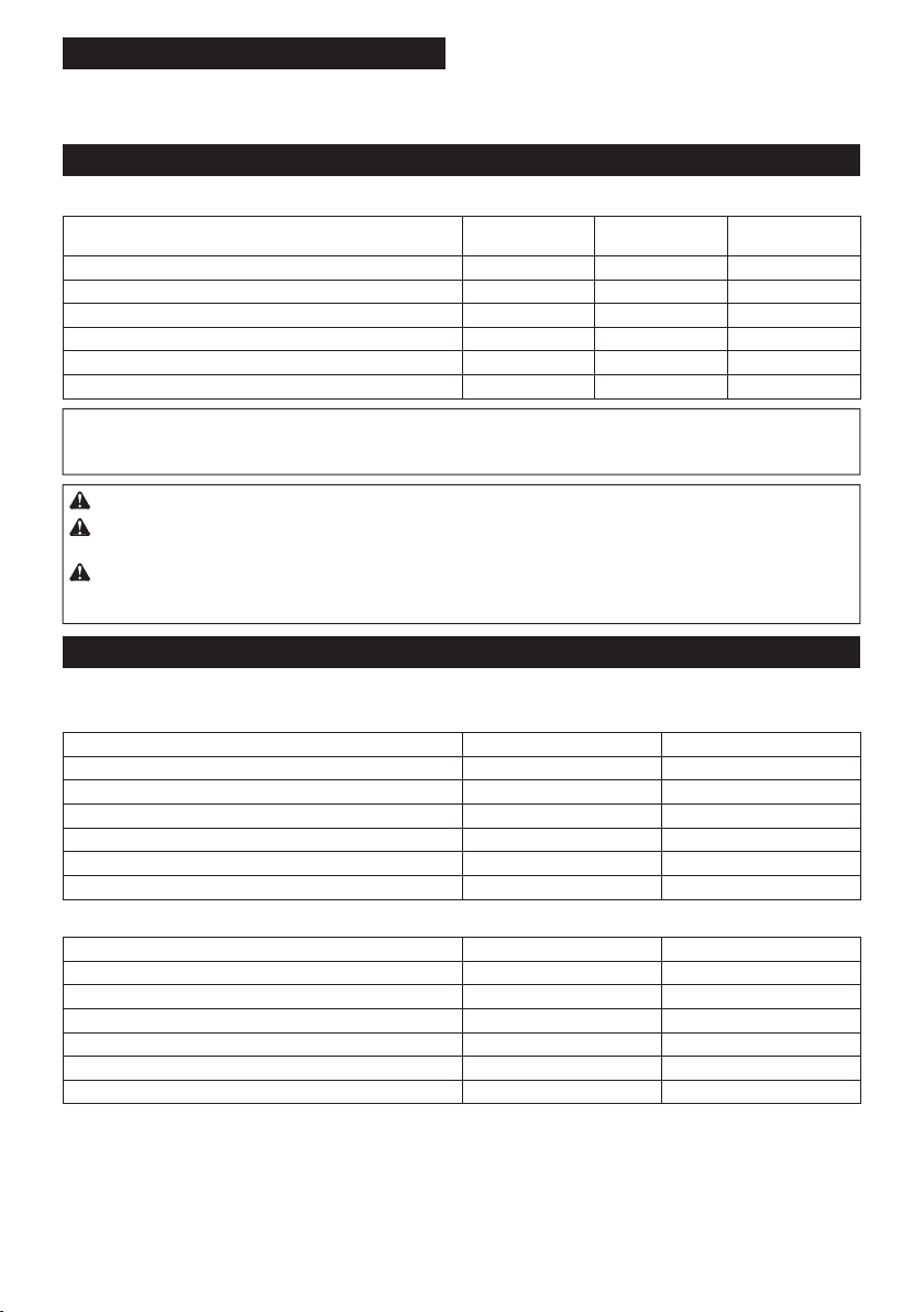
SPECIFICATIONS
Model: GA042G GA043G GA044G GA045G GA046G GA047G
A p p l i c a b l e g r i n d i n g w h e e l M a x . w h e e l d i a m e t e r 100 m m 115 m m 125 m m 100 m m 115 m m 125 m m
M a x . w h e e l t h i c k n e s s 6 m m
M a x . w h e e l d i a m e t e r 100 m m 115 m m 125 m m 100 m m 115 m m 125 m m
M a x . w h e e l t h i c k n e s s 1.6 m m
A p p l i c a b l e w i r e w h e e l b r u s h M a x . w h e e l d i a m e t e r -115 m m -115 m m
M a x . w h e e l t h i c k n e s s -16 m m -16 m m
N o l o a d s p e e d ( n 0) / R a t e d s p e e d ( n ) 8, 500 m i n -1
O v e r a l l l e n g t h ( w i t h B L 4 04 0) 4 3 3 m m 4 18 m m
N e t w e i g h t 3 .0 - 5.4 k g 2.9 -
5.3 k g
3 .0 - 5.3 k g
R a t e d v o l t a g e D.C . 3 6 V - 4 0 V m a x
S p e e d a d j u s t i n g d i a l -
W i r e l e s s a c t i v a t i o n f u n c t i o n -
•
-
e s t c o m b i n a t i o n , a c c o r d i n g t o EP T A -P r o c e d u r e 01/ 2014 , a r e s h o w n i n t h e t a b l e .
Applicable battery cartridge and charger
B L 4 020 / B L 4 025* / B L 4 04 0* / B L 4 050F * / B L 4 080F
C harger DC 4 0R A / DC 4 0R B / DC 4 0R C
•
WARNING: Only use the battery cartridges and chargers listed above.
Recommended cord connected pow er source
P o r t a b l e p o w e r p a c k P DC 01 / P DC 1200
Symbols
-
R e a d i n s t r u c t i o n m a n u a l .
operations.
Ni-MH
Li-ion
Du e t o t h e p r e s e n c e o f h a z a r d o u s c o m -
o n t h e e n v i r o n m e n t a n d h u m a n h e a l t h .
Do n o t d i s p o s e o f e l e c t r i c a l a n d e l e c t r o n i c
a p p l i a n c e s o r b a t t e r i e s w i t h h o u s e h o l d w a s t e !
In a c c o r d a n c e w i t h t h e Eu r o p e a n Di r e c t i v e
a n d o n a c c u m u l a t o r s a n d b a t t e r i e s a n d
w a s t e a c c u m u l a t o r s a n d b a t t e r i e s , a s w e l l a s
t h e i r a d a p t a t i o n t o n a t i o n a l l a w , w a s t e e l e c -
t o a s e p a r a t e c o l l e c t i o n p o i n t f o r m u n i c i p a l
w a s t e , o p e r a t i n g i n a c c o r d a n c e w i t h t h e
r e g u l a t i o n s o n e n v i r o n m e n t a l p r o t e c t i o n .
c r o s s e d -o u t w h e e l e d b i n p l a c e d o n t h e

10 ENGLISH
Intended use
T h e t o o l i s i n t e n d e d f o r g r i n d i n g , s a n d i n g , w i r e b r u s h i n g
a n d c u t t i n g o f m e t a l a n d s t o n e m a t e r i a l s w i t h o u t t h e u s e
o f w a t e r .
Noise
Model Sound pressure
level (LpA) : (dB(A))
Sound pow er level
(LWA) : (dB(A))
Uncertainty (K) :
(dB(A))
G A 04 2G 81 92 3
G A 04 3 G 81 92 3
G A 04 4 G 81 92 3
G A 04 5G 81 92 3
G A 04 6G 81 92 3
G A 04 7 G 81 92 3
NOTE: T h e d e c l a r e d n o i s e e m i s s i o n v a l u e ( s ) h a s b e e n m e a s u r e d i n a c c o r d a n c e w i t h a s t a n d a r d t e s t m e t h o d a n d
NOTE:
WARNING: Wear ear protection.
WARNING: -
ue(s) depending on the w ays in w hich the tool is used especially w hat kind of w orkpiece is processed.
WARNING: Be sure to identify safety measures to protect the operator that are based on an estimation
of exposure in the actual conditions of use (taking account of all parts of the operating cycle such as the
Vibration
T h e v i b r a t i o n t o t a l v a l u e ( t r i -a x i a l v e c t o r s u m ) d e t e r m i n e d a c c o r d i n g t o EN 6284 1-2-3 :
Work mode: surface grinding w ith normal side grip
Model
Vibration emission (ah, AG) : (m/s2)
Uncertainty (K) : (m/s2)
G A 04 2G 3 .3 1.5
G A 04 3 G 3 .7 1.5
G A 04 4 G 4 .5 1.5
G A 04 5G 3 .3 1.5
G A 04 6G 3 .7 1.5
G A 04 7 G 4 .5 1.5
Work mode: surface grinding w ith anti vibration side grip
Model
Vibration emission (ah, AG) : (m/s2)
Uncertainty (K) : (m/s2)
G A 04 2G 3 .6 1.5
G A 04 3 G 4 .0 1.5
G A 04 4 G 5.0 1.5
G A 04 5G 3 .6 1.5
G A 04 6G 4 .0 1.5
G A 04 7 G 5.0 1.5

11 ENGLISH
Work mode: disc sanding w ith normal side grip
Model
Vibration emission (ah, AG) : (m/s2)
Uncertainty (K) : (m/s2)
G A 04 2G 2.5 m / s 2o r l e s s 1.9
G A 04 3 G 2.5 m / s 2o r l e s s 1.9
G A 04 4 G 2.5 m / s 2o r l e s s 1.9
G A 04 5G 2.5 m / s 2o r l e s s 1.9
G A 04 6G 2.5 m / s 2o r l e s s 1.9
G A 04 7 G 2.5 m / s 2o r l e s s 1.9
Work mode: disc sanding w ith anti vibration side grip
Model
Vibration emission (ah, AG) : (m/s2)
Uncertainty (K) : (m/s2)
G A 04 2G 2.5 m / s 2o r l e s s 1.5
G A 04 3 G 2.5 m / s 2o r l e s s 1.5
G A 04 4 G 2.5 m / s 2o r l e s s 1.5
G A 04 5G 2.5 m / s 2o r l e s s 1.5
G A 04 6G 2.5 m / s 2o r l e s s 1.5
G A 04 7 G 2.5 m / s 2o r l e s s 1.5
NOTE: T h e d e c l a r e d v i b r a t i o n t o t a l v a l u e ( s ) h a s b e e n m e a s u r e d i n a c c o r d a n c e w i t h a s t a n d a r d t e s t m e t h o d a n d
NOTE:
WARNING:
value(s) depending on the w ays in w hich the tool is used especially w hat kind of w orkpiece is processed.
WARNING: Be sure to identify safety measures to protect the operator that are based on an estimation
of exposure in the actual conditions of use (taking account of all parts of the operating cycle such as the
WARNING: T h e d e c l a r e d v i b r a t i o n e m i s s i o n v a l u e i s u s e d f o r m a i n a p p l i c a t i o n s o f t h e p o w e r t o o l . H o w e v e r i f
WARNING: Grinding thin sheets of metal or other easily vibrating structures w ith a large surface can
result in a total noise emission much higher (up to 15 dB) than the declared noise emission values.
Take the increased noise emission into consideration for both the risk assessment of noise exposure and
selecting adequate hearing protection.
EC Declaration of Conformity
For European countries only
t o t h i s i n s t r u c t i o n m a n u a l .
SAFETY WARNINGS
General pow er tool safety w arnings
WARNING:
Read all safety w arnings, instruc-
pow er tool. F a i l u r e t o f o l l o w a l l i n s t r u c t i o n s l i s t e d b e l o w
Save all w arnings and instruc-
tions for future reference.
( c o r d l e s s ) p o w e r t o o l .
Cordless grinder safety w arnings
Safety w arnings common for grinding, sanding,
1.
This pow er tool is intended to function as a
all safety w arnings, instructions, illustrations
2.
Operations such as polishing or hole cutting
are not to be performed w ith this pow er tool.
O p e r a t i o n s f o r w h i c h t h e p o w e r t o o l w a s n o t d e s i g n e d
3 . Do not convert this pow er tool to operate in
S u c h a c o n -
4 . Do not use accessories w hich are not spe-
manufacturer.
s a f e o p e r a t i o n .

12 ENGLISH
5. The rated speed of the accessory must be at
least equal to the maximum speed marked on
the pow er tool. A c c e s s o r i e s r u n n i n g f a s t e r t h a n
6. The outside diameter and the thickness of your
accessory must be w ithin the capacity rating
of your pow er tool.
7 . The dimensions of the accessory mounting
-
w are of the pow er tool. A c c e s s o r i e s t h a t d o n o t
m a t c h t h e m o u n t i n g h a r d w a r e o f t h e p o w e r t o o l
8. Do not use a damaged accessory. Before each
use inspect the accessory such as abrasive
w heels for chips and cracks, backing pad for
cracks, tear or excess w ear, w ire brush for
loose or cracked w ires. If pow er tool or acces-
sory is dropped, inspect for damage or install
an undamaged accessory. After inspecting and
installing an accessory, position yourself and
bystanders aw ay from the plane of the rotating
accessory and run the pow er tool at maximum
no-load speed for one minute. Da m a g e d a c c e s -
t i m e .
9. Wear personal protective equipment.
Depending on application, use face shield,
safety goggles or safety glasses. As appro-
priate, w ear dust mask, hearing protectors,
gloves and w orkshop apron capable of stop-
ping small abrasive or w orkpiece fragments.
T h e d u s t m a s k o r r e s p i r a t o r m u s t b e c a p a b l e
10. Keep bystanders a safe distance aw ay from
w ork area. Anyone entering the w ork area
must w ear personal protective equipment.
a r e a o f o p e r a t i o n .
11. Hold the pow er tool by insulated gripping
surfaces only, w hen performing an operation
w here the cutting tool may contact hidden
w iring. C o n t a c t w i t h a " l i v e " w i r e w i l l a l s o m a k e
e x p o s e d m e t a l p a r t s o f t h e p o w e r t o o l " l i v e " a n d
c o u l d g i v e t h e o p e r a t o r a n e l e c t r i c s h o c k .
12. Never lay the pow er tool dow n until the acces-
sory has come to a complete stop. T h e s p i n n i n g
13 . Do not run the pow er tool w hile carrying it at
your side. A c c i d e n t a l c o n t a c t w i t h t h e s p i n n i n g
14 . Regularly clean the pow er tool’s air vents. T h e
m o t o r ’ s f a n w i l l d r a w t h e d u s t i n s i d e t h e h o u s i n g
a n d e x c e s s i v e a c c u m u l a t i o n o f p o w d e r e d m e t a l
15.
materials. S p a r k s c o u l d i g n i t e t h e s e m a t e r i a l s .
16. Do not use accessories that require liquid
coolants.
Kickback and related w arnings:
K i c k b a c k i s a s u d d e n r e a c t i o n t o a p i n c h e d o r s n a g g e d
-
-
t r o l l e d p o w e r t o o l t o b e f o r c e d i n t h e d i r e c t i o n o p p o s i t e
F o r e x a m p l e , i f a n a b r a s i v e w h e e l i s s n a g g e d o r
e n t e r i n g i n t o t h e p i n c h p o i n t c a n d i g i n t o t h e s u r f a c e o f
t h e m a t e r i a l c a u s i n g t h e w h e e l t o c l i m b o u t o r k i c k o u t .
o p e r a t o r , d e p e n d i n g o n d i r e c t i o n o f t h e w h e e l ’ s m o v e -
b r e a k u n d e r t h e s e c o n d i t i o n s .
K i c k b a c k i s t h e r e s u l t o f p o w e r t o o l m i s u s e a n d / o r
i n c o r r e c t o p e r a t i n g p r o c e d u r e s o r c o n d i t i o n s a n d c a n b e
1.
pow er tool and position your body and arms
to allow you to resist kickback forces. Alw ays
use auxiliary handle, if provided, for maxi-
mum control over kickback or torque reaction
during start-up.
r e a c t i o n s o r k i c k b a c k f o r c e s , i f p r o p e r p r e c a u t i o n s
a r e t a k e n .
2. Never place your hand near the rotating acces-
sory.
3 . Do not position your body in the area w here
pow er tool w ill move if kickback occurs.
K i c k b a c k w i l l p r o p e l t h e t o o l i n d i r e c t i o n o p p o s i t e
t o t h e w h e e l ’ s m o v e m e n t a t t h e p o i n t o f s n a g g i n g .
4 . Use special care w hen w orking corners, sharp
edges, etc. Avoid bouncing and snagging the
accessory. C o r n e r s , s h a r p e d g e s o r b o u n c i n g
a n d c a u s e l o s s o f c o n t r o l o r k i c k b a c k .
5. Do not attach a saw chain w oodcarving blade,
segmented diamond w heel w ith a peripheral
gap greater than 10 mm or toothed saw blade.
c o n t r o l .
-
1.
designed for the selected w heel. W h e e l s f o r
w h i c h t h e p o w e r t o o l w a s n o t d e s i g n e d c a n n o t b e
2. The grinding surface of centre depressed
w heels must be mounted below the plane of
the guard lip.
p r o j e c t s t h r o u g h t h e p l a n e o f t h e g u a r d l i p c a n n o t
3 . The guard must be securely attached to the
pow er tool and positioned for maximum safety,
so the least amount of w heel is exposed
tow ards the operator. T h e g u a r d h e l p s t o p r o t e c t
t h e o p e r a t o r f r o m b r o k e n w h e e l f r a g m e n t s , a c c i -
d e n t a l c o n t a c t w i t h w h e e l a n d s p a r k s t h a t c o u l d
i g n i t e c l o t h i n g .

13 ENGLISH
4 .
-
tions. For example: do not grind w ith the side of
f o r p e r i p h e r a l g r i n d i n g , s i d e f o r c e s a p p l i e d t o t h e s e
5.
of correct size and shape for your selected
w heel.
6. Do not use w orn dow n w heels from larger
pow er tools. A w h e e l i n t e n d e d f o r l a r g e r p o w e r
t o o l i s n o t s u i t a b l e f o r t h e h i g h e r s p e e d o f a
7 . When using dual purpose w heels alw ays use
the correct guard for the application being
performed.
n o t p r o v i d e t h e d e s i r e d l e v e l o f g u a r d i n g , w h i c h
operations:
1. -
sive pressure. Do not attempt to make an
excessive depth of cut. O v e r s t r e s s i n g t h e w h e e l
o r b i n d i n g o f t h e w h e e l i n t h e c u t a n d t h e p o s s i b i l -
2. Do not position your body in line w ith and
behind the rotating w heel. W h e n t h e w h e e l , a t
-
3 . When the w heel is binding or w hen interrupt-
tool and hold it motionless until the w heel
comes to a complete stop. Never attempt to
the w heel is in motion otherw ise kickback may
occur. In v e s t i g a t e a n d t a k e c o r r e c t i v e a c t i o n t o
e l i m i n a t e t h e c a u s e o f w h e e l b i n d i n g .
4 . Do not restart the cutting operation in the
w orkpiece. Let the w heel reach full speed and
carefully re-enter the cut.
w a l k u p o r k i c k b a c k i f t h e p o w e r t o o l i s r e s t a r t e d i n
t h e w o r k p i e c e .
5. Support panels or any oversized w orkpiece to
minimize the risk of w heel pinching and kick-
back. L a r g e w o r k p i e c e s t e n d t o s a g u n d e r t h e i r
o w n w e i g h t . S u p p o r t s m u s t b e p l a c e d u n d e r t h e
w o r k p i e c e n e a r t h e l i n e o f c u t a n d n e a r t h e e d g e
o f t h e w o r k p i e c e o n b o t h s i d e s o f t h e w h e e l .
6. Use extra caution w hen making a “ pocket cut”
into existing w alls or other blind areas. T h e
-
t r i c a l w i r i n g o r o b j e c t s t h a t c a n c a u s e k i c k b a c k .
7 . Do not attempt to do curved cutting.
O v e r s t r e s s i n g t h e w h e e l i n c r e a s e s t h e l o a d i n g a n d
8. Before using a segmented diamond w heel,
make sure that the diamond w heel has the
peripheral gap betw een segments of 10 mm or
less, only w ith a negative rake angle.
1. Use proper sized sanding disc paper. Follow
manufacturers recommendations, w hen
selecting sanding paper. Largersanding paper
-
t e a r i n g o f t h e d i s c o r k i c k b a c k .
operations:
1. Be aw are that w ire bristles are throw n by the
brush even during ordinary operation. Do not
overstress the w ires by applying excessive
load to the brush.
p e n e t r a t e l i g h t c l o t h i n g a n d / o r s k i n .
2.
brushing, do not allow any interference of the
w ire w heel or brush w ith the guard. W i r e w h e e l
a n d c e n t r i f u g a l f o r c e s .
Additional Safety Warnings:
1.
When using depressed centre grinding w heels,
2. NEVER USE Stone Cup type w heels w ith this
grinder. T h i s g r i n d e r i s n o t d e s i g n e d f o r t h e s e
3 . Be careful not to damage the X -LOCK holder.
Damage to the parts could result in w heel
breakage.
4 . Make sure the w heel is not contacting the
w orkpiece before the sw itch is turned on.
5. Before using the tool on an actual w orkpiece,
let it run for a w hile. Watch for vibration or
w obbling that could indicate poor installation
or a poorly balanced w heel.
6. -
form the grinding.
7 . Do not leave the tool running. Operate the tool
only w hen hand-held.
8. Do not touch the w orkpiece immediately after
operation; it may be extremely hot and could
burn your skin.
9. Do not touch accessories immediately after
operation; it may be extremely hot and could
burn your skin.
10. Observe the instructions of the manufacturer
for correct mounting and use of w heels.
Handle and store w heels w ith care.
11. Do not use separate reducing bushings or
adaptors to adapt large hole abrasive w heels.
12. Check that the w orkpiece is properly
supported.
13 . Pay attention that the w heel continues to
14 . If w orking place is extremely hot and humid,
or badly polluted by conductive dust, use a
short-circuit breaker (30 mA) to assure opera-
tor safety.
15. Do not use the tool on any materials contain-
ing asbestos.
16.
the dust collecting w heel guard if required by
domestic regulation.

14 ENGLISH
17 . Cutting discs must not be subjected to any
lateral pressure.
18. Do not use cloth w ork gloves during operation.
c a u s e s t o o l b r e a k a g e .
19.
Before operation, make sure that there is no
buried object such as electric pipe, w ater pipe or
gas pipe in the w orkpiece.
a n e l e c t r i c s h o c k , e l e c t r i c a l l e a k a g e o r g a s l e a k .
SAVE THESE INSTRUCTIONS.
WARNING: DO NOT let comfort or familiarity
w ith product (gained from repeated use) replace
strict adherence to safety rules for the subject
product. MISUSE or failure to follow the safety
rules stated in this instruction manual may cause
serious personal injury.
Important safety instructions for
battery cartridge
1.
Before using battery cartridge, read all instruc-
tions and cautionary markings on (1) battery
charger, (2) battery, and (3) product using battery.
2. Do not disassemble or tamper w ith the battery
cartridge.
o r e x p l o s i o n .
3 . If operating time has become excessively
shorter, stop operating immediately. It may
result in a risk of overheating, possible burns
and even an explosion.
4 . If electrolyte gets into your eyes, rinse them
out w ith clear w ater and seek medical atten-
tion right aw ay. It may result in loss of your
eyesight.
5. Do not short the battery cartridge:
( 1) Do not touch the terminals w ith any con-
ductive material.
( 2) Avoid storing battery cartridge in a con-
tainer w ith other metal objects such as
nails, coins, etc.
( 3 ) Do not expose battery cartridge to w ater
or rain.
A battery short can cause a large current
breakdow n.
6. Do not store and use the tool and battery car-
tridge in locations w here the temperature may
reach or exceed 50 ° C (122 ° F).
7 . Do not incinerate the battery cartridge even if
it is severely damaged or is completely w orn
8. Do not nail, cut, crush, throw , drop the battery
cartridge, or hit against a hard object to the
battery cartridge.
9. Do not use a damaged battery.
10. The contained lithium-ion batteries are subject
to the Dangerous Goods Legislation require-
ments.
-
a g i n g a n d l a b e l i n g m u s t b e o b s e r v e d .
F o r p r e p a r a t i o n o f t h e i t e m b e i n g s h i p p e d , c o n s u l t -
nationalregulations.
a r o u n d i n t h e p a c k a g i n g .
11. When disposing the battery cartridge, remove
it from the tool and dispose of it in a safe
place. Follow your local regulations relating to
disposal of battery.
12. Use the batteries only w ith the products
In s t a l l i n g t h e b a t t e r i e s t o
-
13 . If the tool is not used for a long period of time,
the battery must be removed from the tool.
14 . During and after use, the battery cartridge may
take on heat w hich can cause burns or low
temperature burns. Pay attention to the han-
dling of hot battery cartridges.
15. Do not touch the terminal of the tool imme-
diately after use as it may get hot enough to
cause burns.
16. Do not allow chips, dust, or soil stuck into the
terminals, holes, and grooves of the battery
cartridge.
-
17 . Unless the tool supports the use near
high-voltage electrical pow er lines, do not use
the battery cartridge near a high-voltage elec-
trical pow er lines.
18. Keep the battery aw ay from children.
SAVE THESE INSTRUCTIONS.
CAUTION: Only use genuine Makita batteries.
U s e o f n o n -g e n u i n e M a k i t a b a t t e r i e s , o r b a t t e r i e s t h a t
c h a r g e r .
Tips for maintaining maximum
battery life
1. Charge the battery cartridge before completely
discharged. Alw ays stop tool operation and
charge the battery cartridge w hen you notice
less tool pow er.
2. Never recharge a fully charged battery car-
tridge. Overcharging shortens the battery
service life.
3 . Charge the battery cartridge w ith room tem-
perature at 10 ° C - 40 ° C (50 ° F - 104 ° F). Let
a hot battery cartridge cool dow n before
charging it.
4 . When not using the battery cartridge, remove
it from the tool or the charger.
5. Charge the battery cartridge if you do not use
it for a long period (more than six months).

15 ENGLISH
Important safety instructions for
w ireless unit
1. Do not disassemble or tamper w ith the w ire-
less unit.
2. Keep the w ireless unit aw ay from young chil-
dren. If accidentally sw allow ed, seek medical
attention immediately.
3 . Use the w ireless unit only w ith Makita tools.
4 . Do not expose the w ireless unit to rain or w et
conditions.
5. Do not use the w ireless unit in places w here
the temperature exceeds 50 ° C (122 ° F).
6. Do not operate the w ireless unit in places
w here medical instruments, such as heart
pace makers are nearby.
7 . Do not operate the w ireless unit in places
w here automated devices are nearby. If o p e r -
o r e r r o r .
8. Do not operate the w ireless unit in places
under high temperature or places w here
static electricity or electrical noise could be
generated.
9. The w ireless unit can produce electromagnetic
user.
10. The w ireless unit is an accurate instrument. Be
careful not to drop or strike the w ireless unit.
11. Avoid touching the terminal of the w ireless
unit w ith bare hands or metallic materials.
12. Alw ays remove the battery on the product
w hen installing the w ireless unit into it.
13 . When opening the lid of the slot, avoid the
place w here dust and w ater may come into the
slot. Alw ays keep the inlet of the slot clean.
14 . Alw ays insert the w ireless unit in the correct
direction.
15. Do not press the w ireless activation button
on the w ireless unit too hard and/or press the
button w ith an object w ith a sharp edge.
16. Alw ays close the lid of the slot w hen
operating.
17 . Do not remove the w ireless unit from the slot
w hile the pow er is being supplied to the tool.
u n i t .
18. Do not remove the sticker on the w ireless unit.
19. Do not put any sticker on the w ireless unit.
20. Do not leave the w ireless unit in a place w here
static electricity or electrical noise could be
generated.
21. Do not leave the w ireless unit in a place sub-
ject to high heat, such as a car sitting in the
sun.
22. Do not leave the w ireless unit in a dusty or
pow dery place or in a place corrosive gas
could be generated.
23 . Sudden change of the temperature may bedew
the w ireless unit. Do not use the w ireless unit
until the dew is completely dried.
24 . When cleaning the w ireless unit, gently w ipe
w ith a dry soft cloth. Do not use benzine, thin-
ner, conductive grease or the like.
25. When storing the w ireless unit, keep it in the
supplied case or a static-free container.
26. Do not insert any devices other than Makita
w ireless unit into the slot on the tool.
27 . Do not use the tool w ith the lid of the slot dam-
aged.
c a u s e m a l f u n c t i o n .
28. Do not pull and/or tw ist the lid of the slot more
than necessary.
f r o m t h e t o o l .
29. Replace the lid of the slot if it is lost or
damaged.
SAVE THESE INSTRUCTIONS.
FUNCTIONAL
DESCRIPTION
CAUTION: Alw ays be sure that the tool is
before adjusting or checking function on the tool.
Installing or removing battery
cartridge
CAUTION:
installing or removing of the battery cartridge.
CAUTION: Hold the tool and the battery car-
cartridge.
w h i l e s l i d i n g t h e b u t t o n o n t h e f r o n t o f t h e c a r t r i d g e .
Fig.1: 1. R e d i n d i c a t o r 2. B u t t o n 3.
CAUTION: Alw ays install the battery cartridge
fully until the red indicator cannot be seen. If n o t ,
CAUTION: Do not install the battery cartridge
forcibly.

16 ENGLISH
Indicating the remaining battery
capacity
-
l i g h t u p f o r a f e w s e c o n d s .
Fig.2: 1. In d i c a t o r l a m p s 2. C h e c k b u t t o n
Indicator lamps Remaining
capacity
Lighted Blinking
7 5% t o 100%
50% t o 7 5%
25% t o 50%
0% t o 25%
C h a r g e t h e
m a l f u n c t i o n e d .
NOTE: De p e n d i n g o n t h e c o n d i t i o n s o f u s e a n d t h e
NOTE:
Tool / battery protection system
-
-
p l a c e d u n d e r o n e o f t h e f o l l o w i n g c o n d i t i o n s :
Overload protection
-
c a u s e d t h e t o o l t o b e c o m e o v e r l o a d e d . T h e n t u r n t h e
t o o l o n t o r e s t a r t .
Overheat protection
t o o l o n a g a i n .
Overdischarge protection
Releasing protection lock
In t h i s s i t u a t i o n , t h e t o o l d o e s n o t s t a r t e v e n i f t u r n i n g
Protections against other causes
t h a t c o u l d d a m a g e t h e t o o l a n d a l l o w s t h e t o o l t o s t o p
h a l t o r s t o p i n o p e r a t i o n .
1.
Sw itch action
CAUTION: Before installing the battery car-
tridge into the tool, alw ays check to see that the
sw itch lever actuates properly and returns to the
" OFF" position w hen released.
CAUTION: For your safety, this tool is
tool from unintended starting. NEVER use the tool
if it runs w hen you simply pull the sw itch lever
to our authorized service center for proper repairs
BEFORE further usage.
CAUTION: Do not pull the sw itch lever hard
T h i s c a n c a u s e
s w i t c h b r e a k a g e .
CAUTION: NEVER tape dow n or defeat pur-
-
t o r a n d t h e n p u l l t h e s w i t c h l e v e r .
T o s t o p t h e t o o l , r e l e a s e t h e s w i t c h l e v e r .
Fig.3: 1. 2. S w i t c h l e v e r
Speed adjusting dial
Only for model GA042G / GA043G / GA044G
-
i n g t h e s p e e d a d j u s t i n g d i a l . T h e t a b l e b e l o w s h o w s
t h e n u m b e r o n t h e d i a l a n d t h e c o r r e s p o n d i n g r o t a t i o n
speed.
Fig.4: 1. S p e e d a d j u s t i n g d i a l
Number Speed
13 , 000 m i n -1
24 , 500 m i n -1
36, 000 m i n -1
47 , 500 m i n -1
58, 500 m i n -1

17 ENGLISH
NOTICE: If the tool is operated continuously at
low speed for a long time, the motor w ill get over-
loaded, resulting in tool malfunction.
NOTICE: The speed adjusting dial can be turned
only as far as 5 and back to 1. Do not force it past
5 or 1, or the speed adjusting function may no
longer w ork.
Electric brake
t h e s w i t c h s t i l l o n .
C e n t e r .
Electronic function
Accidental re-start preventive
function
O N , t h e t o o l d o e s n o t s t a r t .
Active Feedback sensing Technology
f u r t h e r r o t a t i o n o f t h e s p i n d l e ( i t d o e s n o t p r e v e n t
k i c k b a c k ) .
c a u s e o f s u d d e n d r o p i n t h e r o t a t i o n s p e e d , a n d t h e n
t u r n t h e t o o l o n .
Soft start feature
S o f t s t a r t f e a t u r e r e d u c e s s t a r t i n g r e a c t i o n .
ASSEMBLY
CAUTION: Alw ays be sure that the tool is
before adjusting or checking function on the tool.
Installing side grip (handle)
CAUTION: Alw ays be sure that the side grip is
installed securely before operation.
Fig.5
Installing or removing w heel guard
WARNING: When using a depressed center
closed side of the guard alw ays points tow ard the
operator.
WARNING: Make sure that the w heel guard is
securely locked by the lock lever w ith one of the
holes on the w heel guard.
WARNING:
/ diamond w heel, be sure to use only the special
disc, w ire w heel brush / abrasive cut-
1. W h i l e p u s h i n g t h e l o c k l e v e r , m o u n t t h e w h e e l
g u a r d w i t h t h e p r o t r u s i o n s o n t h e w h e e l g u a r d a l i g n e d
w i t h t h e n o t c h e s o n t h e b e a r i n g b o x .
Fig.6: 1. L o c k l e v e r 2. N o t c h 3. P r o t r u s i o n
2.
W h i l e p u s h i n g t h e l o c k l e v e r t o w a r d A , h o l d d o w n
Fig.7: 1. W h e e l g u a r d 2. H o l e
NOTE: P u s h d o w n t h e w h e e l g u a r d s t r a i g h t .
3. W h i l e p u s h i n g t h e l o c k l e v e r t o w a r d A , r o t a t e t h e
w h e e l g u a r d t o w a r d C , a n d t h e n , c h a n g e t h e a n g l e o f
t h e w h e e l g u a r d a c c o r d i n g t o t h e w o r k s o t h a t t h e o p e r -
a t o r c a n b e p r o t e c t e d . A l i g n t h e l o c k l e v e r w i t h o n e o f
t h e h o l e s i n t h e w h e e l g u a r d , a n d t h e n r e l e a s e t h e l o c k
l e v e r t o l o c k t h e w h e e l g u a r d .
Fig.8: 1. W h e e l g u a r d 2. H o l e
T o r e m o v e w h e e l g u a r d , f o l l o w t h e i n s t a l l a t i o n p r o c e -
d u r e i n r e v e r s e .
Installing depressed center w heel or
Optional accessory
WARNING: When using a depressed center
guard alw ays points tow ard the operator.
Fig.9: 1. De p r e s s e d c e n t e r w h e e l 2. W heelguard
Optional accessory
WARNING:
/ diamond w heel, be sure to use only the special
WARNING:
grinding.
Fig.10: 1.
2.
diam ond w heel

18 ENGLISH
Clip-on cutting w heel guard
attachment
Optional accessory
NOTE:
w h e e l g u a r d a t t a c h m e n t c a n b e u s e d w i t h t h e w h e e l
g u a r d ( f o r g r i n d i n g w h e e l ) .
N o t a v a i l a b l e i n s o m e c o u n t r i e s .
Fig.11
Installing w ire cup brush
Optional accessory
CAUTION: Do not use w ire cup brush that is
damaged, or w hich is out of balance. U s e o f d a m -
c o n t a c t w i t h b r o k e n b r u s h w i r e s .
Fig.12: 1. W i r e c u p b r u s h
Installing w ire w heel brush
Optional accessory
CAUTION: Do not use w ire w heel brush that
is damaged, or w hich is out of balance. U s e o f
d a m a g e d w i r e w h e e l b r u s h c o u l d i n c r e a s e p o t e n t i a l
CAUTION: ALWAYS use guard w ith w ire
inside guard. W h e e l c a n s h a t t e r d u r i n g u s e a n d
Fig.13: 1. W i r e w h e e l b r u s h 2. W heelguard
Installing or removing X -LOCK w heel
WARNING: Never actuate the release lever of
the X -LOCK holder during operation. Make sure
that the X -LOCK w heel has stopped completely
w hen removing it. O t h e r w i s e , t h e X -L O C K w h e e l
CAUTION: Use only original X -LOCK w heels
w ith the X -LOCK logo. T h i s t o o l i s d e d i c a t e d t o
X -L O C K .
g u a r a n t e e d w i t h o r i g i n a l X -L O C K w h e e l s .
-
i n g , a n d c a u s e t h e c l a m p t o o l t o c o m e l o o s e .
CAUTION: Do not touch the X -LOCK w heel
immediately after operation.
CAUTION: Make sure that the X -LOCK w heel
and holder of the tool are not deformed and are
free from dust or foreign matters.
CAUTION:
holder w hile installing or removing the X -LOCK
w heel.
CAUTION:
release lever w hile installing the X -LOCK w heel. It
NOTE:
X -L O C K w h e e l s .
1. T o i n s t a l l t h e X -L O C K w h e e l , m a k e s u r e t h a t b o t h
c a t c h e s a r e i n t h e u n l o c k e d p o s i t i o n .
If n o t , p u s h t h e r e l e a s e l e v e r f r o m A s i d e t o l i f t B
s i d e , t h e n p u l l t h e r e l e a s e l e v e r f r o m B s i d e a s
i l l u s t r a t e d . T h e c a t c h e s a r e s e t i n t h e u n l o c k e d
p o s i t i o n .
Fig.14: 1. C a t c h 2. R e l e a s e l e v e r
2. P l a c e a c e n t r a l p o s i t i o n o f t h e X -L O C K w h e e l o n
t h e h o l d e r .
M a k e s u r e t h e X -L O C K w h e e l i s p a r a l l e l t o t h e
3 . P u s h t h e X -L O C K w h e e l i n t o t h e h o l d e r . T h e
c a t c h e s s n a p i n t o t h e l o c k p o s i t i o n w i t h a c l i c k a n d
Fig.15: 1. X -L O C K w h e e l 2. H o l d e r 3. F l a n g e s u r -
f a c e 4. C a t c h
T h e s u r f a c e o f t h e X -L O C K w h e e l i s n o h i g h e r
t h a n t h e s u r f a c e o f t h e h o l d e r a s s h o w n i n t h e
If n o t , t h e h o l d e r m u s t b e c l e a n e d o r t h e X -L O C K
w h e e l m u s t n o t b e u s e d .
Fig.16: 1. S u r f a c e o f t h e h o l d e r 2. S u r f a c e o f t h e
X -L O C K w h e e l
T o r e m o v e t h e X -L O C K w h e e l , p u s h t h e r e l e a s e l e v e r
f r o m A s i d e t o l i f t B s i d e , t h e n p u l l t h e r e l e a s e l e v e r f r o m
B s i d e a s i l l u s t r a t e d .
T h e X -L O C K w h e e l i s r e l e a s e d a n d c a n b e r e m o v e d .
Fig.17: 1. R e l e a s e l e v e r
Installing dust collecting w heel
Optional accessory
c u t t i n g s t o n e m a t e r i a l s .
Fig.18
NOTE: F o r i n f o r m a t i o n h o w t o i n s t a l l t h e d u s t c o l -
l e c t i n g w h e e l g u a r d , r e f e r t o t h e m a n u a l o f t h e d u s t
c o l l e c t i n g w h e e l g u a r d .
Connecting a vacuum cleaner
Optional accessory
WARNING: Never vacuum metal particles
created by grinding/cutting/sanding operation.
c l e a n e r .
-
t i n g , u s e a d u s t c o l l e c t i n g w h e e l g u a r d a n d a v a c u u m
c l e a n e r .
R e f e r t o t h e i n s t r u c t i o n m a n u a l a t t a c h e d t o t h e d u s t
c o l l e c t i n g w h e e l g u a r d f o r a s s e m b l i n g a n d u s i n g i t .
Fig.19: 1. Du s t c o l l e c t i n g w h e e l g u a r d 2. H o s e o f
t h e v a c u u m c l e a n e r

19 ENGLISH
OPERATION
WARNING: It should never be necessary to
force the tool. T h e w e i g h t o f t h e t o o l a p p l i e s a d e -
c o u l d c a u s e d a n g e r o u s w h e e l b r e a k a g e .
WARNING: ALWAYS replace w heel if tool is
dropped w hile grinding.
WARNING: NEVER hit the w orkpiece w ith the
w heel.
WARNING: Avoid bouncing and snagging
the w heel, especially w hen w orking corners,
sharp edges etc. T h i s c a n c a u s e l o s s o f c o n t r o l a n d
k i c k b a c k .
WARNING: NEVER use tool w ith w ood cutting
blades and other saw blades. S u c h b l a d e s w h e n
WARNING: Never actuate the release lever of
the X -LOCK holder during operation. T h e X -L O C K
WARNING: Make sure that the X -LOCK w heel
CAUTION: Never sw itch on the tool w hen it
is in contact w ith the w orkpiece, it may cause an
injury to operator.
CAUTION: Alw ays w ear safety goggles or a
face shield during operation.
CAUTION:
the tool and w ait until the w heel has come to a
complete stop before putting the tool dow n.
CAUTION:
one hand on housing and the other on the side
grip (handle).
Grinding and sanding operation
Fig.20
w o r k p i e c e .
In g e n e r a l , k e e p t h e e d g e o f t h e w h e e l o r d i s c a t a n
a n g l e o f a b o u t 15° t o t h e w o r k p i e c e s u r f a c e .
Du r i n g t h e b r e a k -i n p e r i o d w i t h a n e w w h e e l , d o n o t
t h e w o r k p i e c e . O n c e t h e e d g e o f t h e w h e e l h a s b e e n
f o r w a r d a n d b a c k w a r d d i r e c t i o n .
diamond w heel
Optional accessory
WARNING: Do not " jam" the w heel or apply
excessive pressure. Do not attempt to make an
excessive depth of cut. O v e r s t r e s s i n g t h e w h e e l
o f k i c k b a c k , w h e e l b r e a k a g e a n d o v e r h e a t i n g o f t h e
WARNING: Do not start the cutting operation
in the w orkpiece. Let the w heel reach full speed
and carefully enter into the cut moving the tool
forw ard over the w orkpiece surface. T h e w h e e l
s t a r t e d i n t h e w o r k p i e c e .
WARNING: During cutting operations, never
change the angle of the w heel. P l a c i n g s i d e p r e s -
t h e w h e e l t o c r a c k a n d b r e a k , c a u s i n g s e r i o u s p e r -
WARNING: A diamond w heel shall be oper-
ated perpendicular to the material being cut.
w heel
Fig.21
Usage example: operation w ith diamond w heel
Fig.22
Operation w ith w ire cup brush
Optional accessory
CAUTION: Check operation of brush by run-
ning tool w ith no load, insuring that no one is in
front of or in line w ith brush.
NOTICE: Avoid applying too much pressure
w hich causes over bending of w ires w hen using
the w ire cup brush.
breakage.
Usage example: operation w ith w ire cup brush
Fig.23
Operation w ith w ire w heel brush
Optional accessory
CAUTION: Check operation of w ire w heel
brush by running tool w ith no load, insuring that
no one is in front of or in line w ith the w ire w heel
brush.
NOTICE: Avoid applying too much pressure
w hich causes over bending of w ires w hen
using w ire w heel brush.
breakage.
Usage example: operation w ith w ire w heel brush
Fig.24

20 ENGLISH
WIRELESS ACTIVATION
FUNCTION
Only for model GA042G / GA043G / GA044G
What you can do w ith the w ireless
activation function
T h e w i r e l e s s a c t i v a t i o n f u n c t i o n e n a b l e s c l e a n a n d c o m -
Fig.25
T o u s e t h e w i r e l e s s a c t i v a t i o n f u n c t i o n , p r e p a r e f o l l o w -
i n g i t e m s :
•A v a c u u m c l e a n e r w h i c h s u p p o r t s t h e w i r e l e s s
a c t i v a t i o n f u n c t i o n
T h e o v e r v i e w o f t h e w i r e l e s s a c t i v a t i o n f u n c t i o n
s e t t i n g i s a s f o l l o w s . R e f e r t o e a c h s e c t i o n f o r d e t a i l
procedures.
1. In s t a l l i n g t h e w i r e l e s s u n i t
2. T o o l r e g i s t r a t i o n f o r t h e v a c u u m c l e a n e r
3. S t a r t i n g t h e w i r e l e s s a c t i v a t i o n f u n c t i o n
Installing the w ireless unit
Optional accessory
CAUTION:
surface w hen installing the w ireless unit.
NOTICE: Clean the dust and dirt on the tool
before installing the w ireless unit. Du s t o r d i r t
w i r e l e s s u n i t .
NOTICE: To prevent the malfunction caused by
static, touch a static discharging material, such
as a metal part of the tool, before picking up the
w ireless unit.
NOTICE: When installing the w ireless unit,
alw ays be sure that the w ireless unit is inserted
in the correct direction and the lid is completely
closed.
1.
Fig.26: 1. L i d
2. In s e r t t h e w i r e l e s s u n i t t o t h e s l o t a n d t h e n c l o s e
t h e l i d .
W h e n i n s e r t i n g t h e w i r e l e s s u n i t , a l i g n t h e p r o j e c t i o n s
w i t h t h e r e c e s s e d p o r t i o n s o n t h e s l o t .
Fig.27: 1. W i r e l e s s u n i t 2. P r o j e c t i o n 3. L i d
4. R e c e s s e d p o r t i o n
T h e h o o k s o n t h e b a c k o f t h e l i d w i l l l i f t t h e w i r e l e s s u n i t
Fig.28: 1. W i r e l e s s u n i t 2. H o o k 3. L i d
A f t e r r e m o v i n g t h e w i r e l e s s u n i t , k e e p i t i n t h e s u p p l i e d
c a s e o r a s t a t i c -f r e e c o n t a i n e r .
NOTICE: Alw ays use the hooks on the back of
the lid w hen removing the w ireless unit. If t h e
h o o k s d o n o t c a t c h t h e w i r e l e s s u n i t , c l o s e t h e l i d
Tool registration for the vacuum
cleaner
NOTE: A M a k i t a v a c u u m c l e a n e r s u p p o r t i n g t h e
r e g i s t r a t i o n .
NOTE: F i n i s h i n s t a l l i n g t h e w i r e l e s s u n i t t o t h e t o o l
b e f o r e s t a r t i n g t h e t o o l r e g i s t r a t i o n .
NOTE: Du r i n g t h e t o o l r e g i s t r a t i o n , d o n o t p u l l t h e
s w i t c h t r i g g e r o r t u r n o n t h e p o w e r s w i t c h o n t h e
v a c u u m c l e a n e r .
NOTE: R e f e r t o t h e i n s t r u c t i o n m a n u a l o f t h e v a c u u m
c l e a n e r , t o o .
-
tion beforehand.
1. In s t a l l t h e b a t t e r i e s t o t h e v a c u u m c l e a n e r a n d t h e
t o o l .
2.
" A U T O " .
Fig.29: 1.
3. P r e s s t h e w i r e l e s s a c t i v a t i o n b u t t o n o n t h e v a c -
u u m c l e a n e r f o r 3 s e c o n d s u n t i l t h e w i r e l e s s a c t i v a t i o n
l a m p b l i n k s i n g r e e n . A n d t h e n p r e s s t h e w i r e l e s s a c t i -
Fig.30: 1. W i r e l e s s a c t i v a t i o n b u t t o n 2. W i r e l e s s
a c t i v a t i o n l a m p
If t h e v a c u u m c l e a n e r a n d t h e t o o l a r e l i n k e d s u c c e s s -
f o r 2 s e c o n d s a n d s t a r t b l i n k i n g i n b l u e .
NOTE:
i n g r e e n a f t e r 20 s e c o n d s e l a p s e d . P r e s s t h e w i r e l e s s
a c t i v a t i o n b u t t o n o n t h e t o o l w h i l e t h e w i r e l e s s a c t i -
v a t i o n l a m p o n t h e c l e a n e r i s b l i n k i n g . If t h e w i r e l e s s
a c t i v a t i o n l a m p d o e s n o t b l i n k i n g r e e n , p u s h t h e w i r e -
NOTE: W h e n p e r f o r m i n g t w o o r m o r e t o o l r e g i s t r a -
-
Starting the w ireless activation
function
NOTE: F i n i s h t h e t o o l r e g i s t r a t i o n f o r t h e v a c u u m
c l e a n e r p r i o r t o t h e w i r e l e s s a c t i v a t i o n .
NOTE: R e f e r t o t h e i n s t r u c t i o n m a n u a l o f t h e v a c u u m
c l e a n e r , t o o .
A f t e r r e g i s t e r i n g a t o o l t o t h e v a c u u m c l e a n e r , t h e
s w i t c h o p e r a t i o n o f t h e t o o l .
1. In s t a l l t h e w i r e l e s s u n i t t o t h e t o o l .
2. C o n n e c t t h e h o s e o f t h e v a c u u m c l e a n e r w i t h t h e
t o o l .
Fig.31
Other manuals for GA042G
5
This manual suits for next models
9
Table of contents
Languages:
Other Makita Grinder manuals

Makita
Makita M9501 User manual

Makita
Makita 906 User manual

Makita
Makita 9565PCV01 User manual

Makita
Makita GA5020 User manual

Makita
Makita MGA400 User manual

Makita
Makita DGD800 User manual

Makita
Makita M9003G User manual

Makita
Makita MT902 User manual

Makita
Makita GA5080 User manual

Makita
Makita GD0602 User manual

Makita
Makita GA7080 User manual

Makita
Makita M9003 User manual

Makita
Makita GA7050R User manual

Makita
Makita GA7010C User manual

Makita
Makita 9561CH User manual

Makita
Makita DISC GRINDER 9505BH User manual

Makita
Makita DGA419 User manual

Makita
Makita GA7020 User manual

Makita
Makita M9514 User manual

Makita
Makita GS5000 User manual