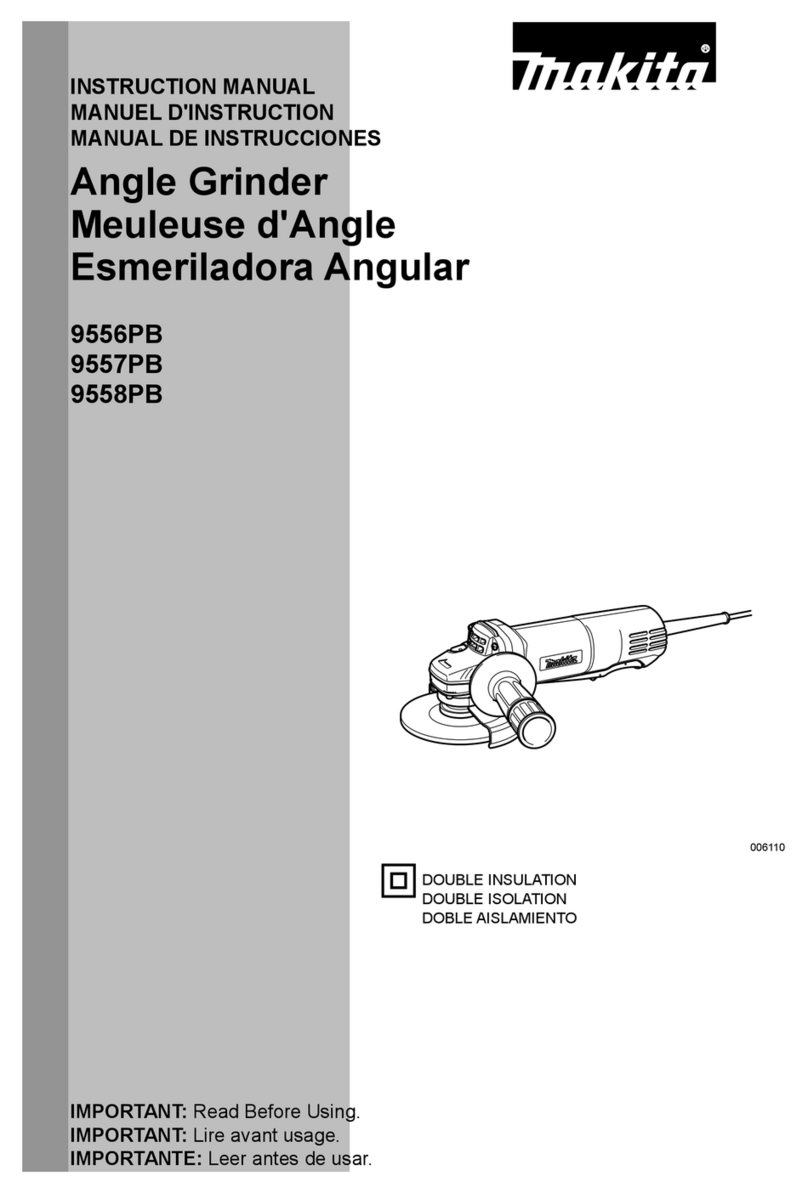
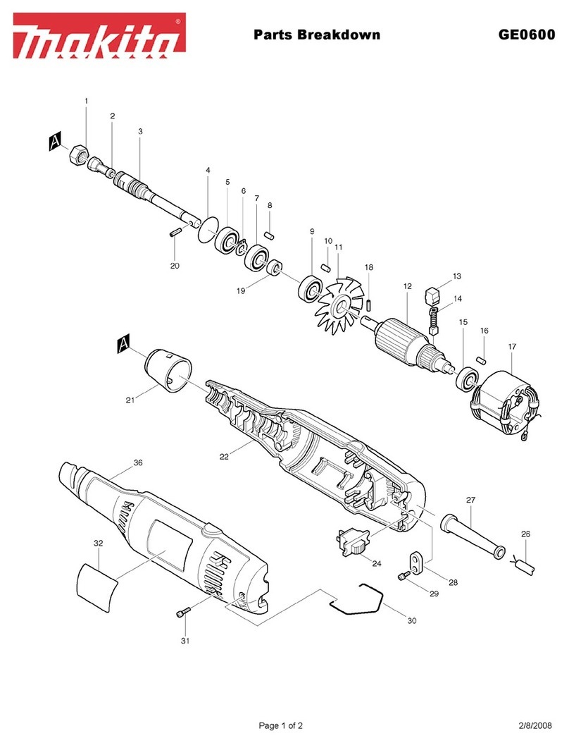
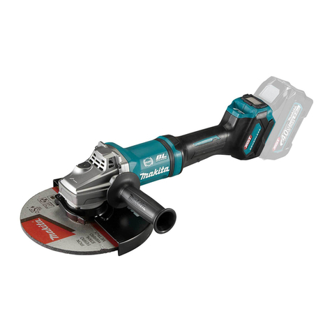
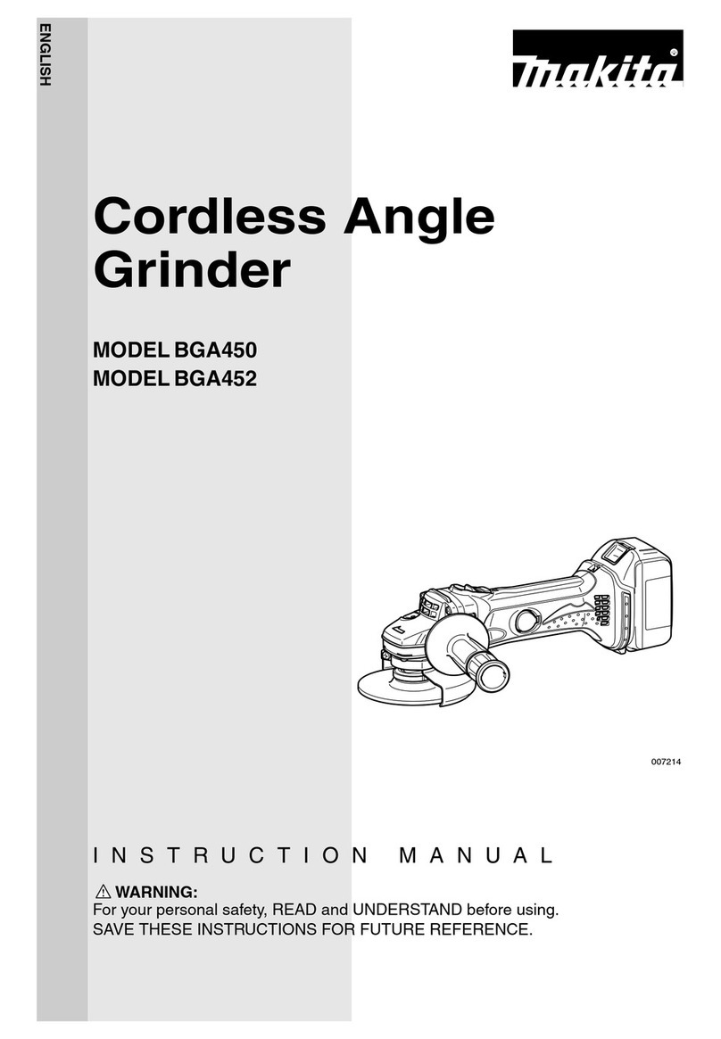
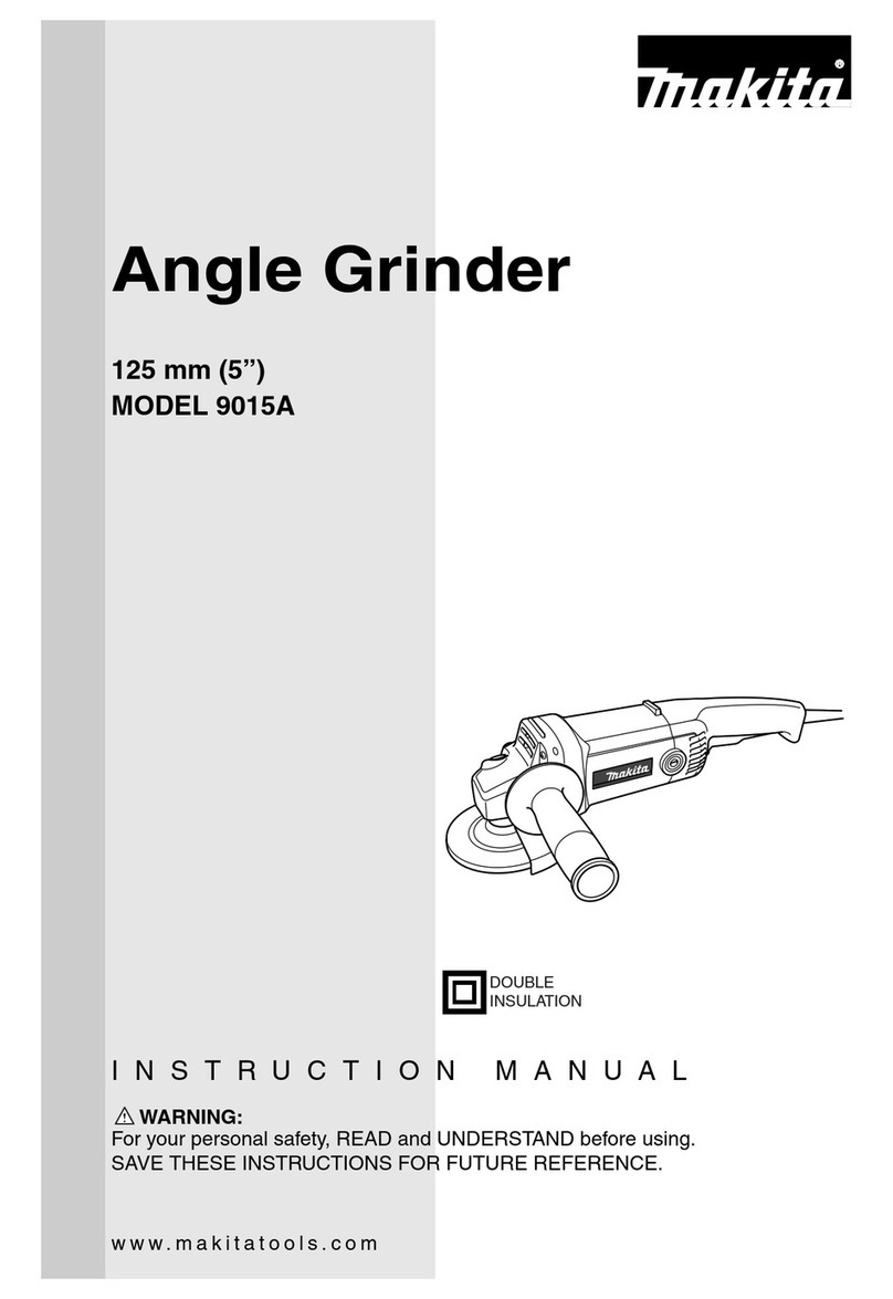
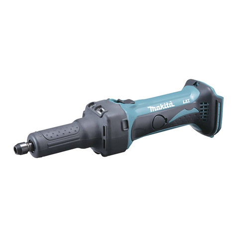
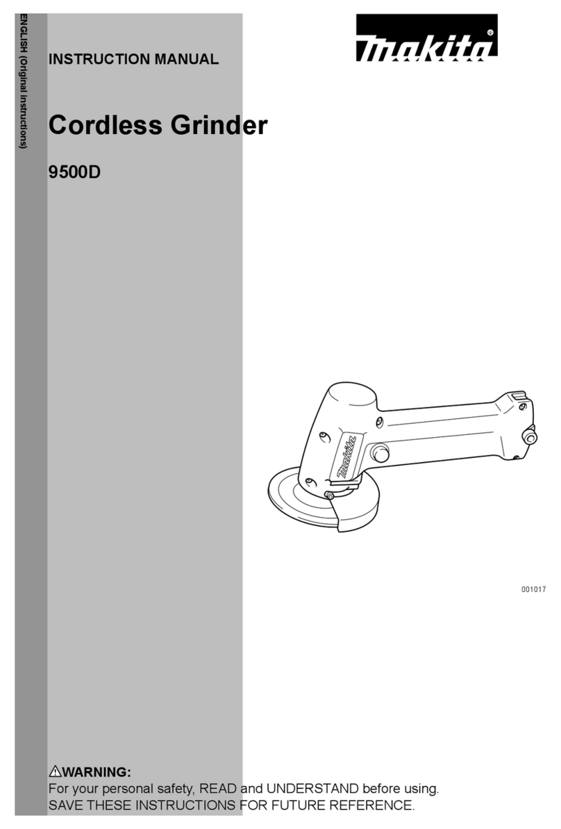
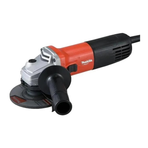
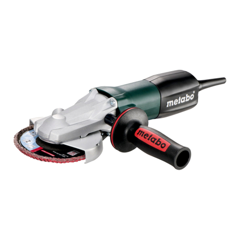
Makita Maktec MT961 Manual

Specification
Standard equipment
Note: The standard equipment for the tool shown above may vary by country.
Lock nut wrench 20 ...................... 1 (for MT961)
Lock nut wrench 35 ...................... 1 (for MT962/ MT963)
Side grip ....................................... 1
Model No.
No load speed: min.-1 = rpm
Diameter
Hole diameter
Wheel size: mm (")
Protection against electric shock
Power supply cord: m (ft)
Weight according to
EPTA-Procedure 01/2003*: kg (lbs)
MT961
100 (4)
2.0 (6.6)
1.9 (4.1) 2.0 (4.4)
11,000
Double insulation
16 (5/8)
MT962
115 (4-1/2)
22.23 (7/8)
MT963
125 (5)
Optional accessories
Wheel cover for Cut-off wheel
Continuous Rating (W)
Voltage (V) Cycle (Hz) Input Output
320
Max. Output (W)
110
120
220
230-240
5.5
5.0
2.7
2.5
50/60
50/60
50/60
50/60
570
---
570
570
650
650
550
550
Current (A)
320
350
350
*With Side grip, Wheel cover, Inner flange, Lock nut
Specification
Dimensions: mm (")
Width (W)
Height (H)
Length (L)
Model No. MT961
270 (10-5/8)
118 (4-5/8)
MT962 MT963
129 (5-1/8)
96 (3-3/4)
139 (5-1/2)
105 (4-1/8)
CONCEPT AND MAIN APPLICATIONS
Model No.
Description
MT961, MT962, MT963
Angle Grinders 100mm (4"), 115mm (4-1/2"), 125mm (5")
These new angle grinders have been developed as the aesthetic
change models of the predecessors MT951/ MT952/ MT953.
Their main features are:
New slide switch (two action safety switch) and wheel cover
in compliance with the requirements of the new regulations
Industrial performance and durability at less expense
L
H
W
P 1/ 10
PRODUCT
TECHNICAL INFORMATION

P 2/ 10
Repair
CAUTION: Repair the machine in accordance with “Instruction manual” or “Safety instructions”.
[1] NECESSARY REPAIRING TOOLS
[2] LUBRICATIONS
[3] DISASSEMBLY/ASSEMBLY
[3]-1. Armature, Spiral bevel gear 11, Ball bearings 6000ZZ and 607ZZ
Fig. 1
Fig. 2
Code No. Description Use for
1R004 Retaining ring S pliers ST-2N removing Ring spring 11 from Spindle
1R005 Retaining ring R pliers RT-2N removing Retaining ring R-32 from Bearing box
1R026 Bearing setting pipe 16-8.2 removing Spindle from Spiral bevel gear 36
1R232 Pipe 30 supporting Bearing box when removing Spindle
1R268 Spring pin extractor 3 disassembling Shaft lock mechanism
1R269 Bearing extractor removing Ball bearing
1R281 Round bar for arbor 7-50 locking Switch knob when separating Switch lever from Switch knob
1R282 Round bar for arbor 8-50 removing Spindle
1R291 Retaining ring S and R pliers removing / assembling Retaining ring S-6 from / to Armature shaft
Item No.
Apply the following lubricant to protect parts and product from unusual abrasion.
Description
1. Remove Carbon brushes and
two 4x18 Tapping screws,
and then remove Rear cover
from Motor housing.
2. Remove four 4x22 Tapping screws
and Gear housing section from
Motor housing.
3. Remove Armature together with
Bearing box from Gear housing
complete.
AmountPortion to lubricate
DISASSEMBLING
17
17 Gear housing complete
(1) Remove Armature. (Fig. 2)
Gear room 10g
Lubricant
Makita grease N No.1
4 x 18 Tapping screw
(2pcs.)
Rear cover
Carbon brush
Bearing box
Gear housing complete
Armature
Carbon brush 4x22 Tapping screw (4pcs.)


P 3/ 10
Repair
[3] DISASSEMBLY/ASSEMBLY
[3]-1. Armature, Spiral bevel gear 11, Ball bearings 6000ZZ and 607ZZ (cont.)
Fig. 3
DISASSEMBLING
ASSEMBLING
(2) Remove Helical gear 11, Ball bearing 6000ZZ and Bearing retainer 69 from Armature. (Fig. 3)
(3) Remove Ball bearing 607ZZ from the commutator end of Armature. (Fig. 4)
(1) Do the reverse of the disassembling steps. (Figs. 4, 3, 2)
Note:
a. Do not forget to put two Flat washer 7 before assembling Ball bearing 607ZZ. (right in Fig. 4)
b. Put Flat washer 10, before assembling Ball bearing 6000ZZ. (center of Fig. 3)
c. Be sure to use new Retaining ring S-6 because removed one was damaged in the removal process. (left in Fig. 3)
d. Assemble Gear housing section to Motor housing by screwing four 4 x 22 Tapping screws. (Fig. 5)
4. Remove Retaining ring S-6
with 1R291. Helical gear 11
can now be removed by hand.
After removing Rubber ring 19, remove Ball bearing 607ZZ
with 1R269.
Remove two Flat washers 7 and
Insulation washer.
Spindle face from Gear housing section
to the opposite side of Switch knob of
Motor housing.
5. Remove Ball bearing 6000ZZ with 1R269,
and then remove Flat washer 10.
6. Armature can be now
removed from Bearing
retainer 69.
Armature
Bearing
retainer 69
Retaining
ring S-6
Helical
gear 11
Flat washer 10
Flat washer 7 (2pcs.)
Ball bearing
6000ZZ
1R269
1R269
Ball bearing 607ZZ Insulation
washer
Rubber ring 19
Fig. 4
Switch knob
Spindle
Fig. 5

P 4/ 10
Repair
[3] DISASSEMBLY/ASSEMBLY
[3]-2. Spiral bevel gear 36
Fig. 6
DISASSEMBLING
(1) Separate Bearing box from Gear housing complete and remove Ring spring from Spindle. (Fig. 6)
(2) Disassemble Spindle. (Fig. 7)
2. Opening Ring spring 11 with 1R004, lift the spring up from
the opposite side of 1R004 with Slotted screwdriver and
remove it from Spindle.
1. Separate Bearing box by unscrewing four M4 x 16
Pan head screws.
M4x16 Pan head
screw (4pcs.)
Bearing box
Ring spring 11
1R004
Fig. 7
1R026
1R026
3. Put Bearing box onto 1R232
and set 1R026 over Spindle.
7. Set 1R282 on Spindle, and remove
Spindle by pressing down with Arbor
press.
4. Set Ram of Arbor press to 20mm
higher position from the top of 1R026.
5. Strike 1R026 carefully with Ram until
Spindle is slightly shifted as illustrated
below.
6. Remove 1R026.
1R232
Bearing
box
20 cm
Spindle Ram
1R282
Spindle
Spiral bevel gear 36
Slotted screwdriver
Note: Do not reuse Ball bearing 6201DDW when Bearing box section is disassembled.
It is inevitably damaged.

P 5/ 10
Repair
[3] DISASSEMBLY/ASSEMBLY
[3]-2. Spiral bevel gear 36 (cont.)
Fig. 8
DISASSEMBLING
(3) From Bearing box, remove Flat washer 12 and Ball bearing 6201DDW. (Fig. 8)
(1) Assemble Flat washer 12 and Ball bearing 6201DDW into Bearing box, and then set Retaining ring R-32
with 1R005. (Fig. 8)
Note: Ball bearing 6201DDW has to be replaced with new one. (Fig. 7)
(2) Assemble Spindle to Bearing box by pressing with Arbor press. (Fig. 7)
(3) Assemble Spiral bevel gear 36 to Spindle by pressing Arbor press and secure Spiral bevel gear 36
with Ring spring 11. (Figs. 7, 6)
Note: Removed Ring spring 11 is always deformed. (right in Fig. 6)
Fit Ring spring 11 to the groove of Spindle with pliers as illustrated in Fig. 9.
6. Remove Retaining ring
R-32 with 1R005.
7B. If the work mentioned
in 7A. is not successful,
remove Ball bearing
6201DDW and Flat
washer 12 with Arbor
press.
Retaining
ring R-32
1R005
Flat washer 12
Flat washer 12
Ball bearing
6201DDW
Ball bearing
6201DDW
7A. Remove Ball bearing
6201DDW and Flat
washer 12 by striking
Bearing box against
Worktable.
ASSEMBLING
Deformed
Ring spring 11
Ring spring 11 has to be corrected
with pliers to be fit to the groove.
Fig. 9

P 6/ 10
Repair
[3] DISASSEMBLY/ASSEMBLY
[3]-3. Switch lever
DISASSEMBLING
ASSEMBLING
Disassemble Switch lever and Switch knob. (Fig. 10)
Assemble Switch lever and switch knob. (Fig. 11)
3. Bending Switch lever, pull it
out from Motor housing.
1. Blocking Switch knob to OFF position
by putting 1R281, strongly push
Switch lever as illustrated below.
2. Linkage of Switch knob is now
disconnected from Switch lever.
Switch knob can be removed.
Switch knob
Motor
housing
Switch knob
Switch
knob
2. Fit the hook of Switch Knob
to the hole of Switch lever.
Switch lever
Switch lever
1R281
Switch lever
Fig. 10
Fig. 11
Switch Switch
Rear end of
Switch lever
1. Insert Switch lever into Motor housing
until the hole of Switch lever comes
into sight through Switch knob
assembling hole on Motor housing.
And keep this position.
Motor
housing
Hook of
Switch knob
Front end of
Switch lever

P 7/ 10
Repair
[3] DISASSEMBLY/ASSEMBLY
[3]-4. Shaft Lock
DISASSEMBLING
ASSEMBLING
Assemble Shaft lock. (Fig. 13)
Fig. 12
(1) Remove Bearing box by unscrewing four M4 x 16 Pan head screws. (left in Fig. 6)
(2) Disassemble Shaft lock mechanism. (Fig. 12)
1. Setting 1R268 to Shoulder pin 4 through
the small hole on Pin cap, tap 1R268 with
Hammer. Shoulder pin 4 comes out from
Gear housing complete.
2. Slowly release 1R268 from Pin cap not to lose
Compression spring 8.
Note: Impossible to reuse Pin cap, because removal of
Shoulder pin 4 damages the inside surface of Pin cap,
producing plastic dust.
1R268
Pin cap
Pin cap
Compression
spring 8
Shoulder pin 4
Fig. 13
Plastic dust
Shoulder pin 4
3. Assemble Compression spring 8
and new Pin cap by pressing it to
Shoulder pin 4.
2. Insert Shoulder pin 4 through
hole of Gear housing complete.
Pin cap
Compression
spring 8
Shoulder
pin 4
Note: Do not reuse the removed Pin cap.
1. Remove all the plastic dust
from the constricted part of
Shoulder pin 4.

Circuit diagram
Wiring diagram
P 8/ 10
White
Color index of lead wires' sheath
Black
Fig. D-1
Fig. D-2
Fig. D-3
Noise suppressor is not used
for some countries.
Noise
suppressor
Terminal
block
Switch
Power supply cord
Field
Field lead wire (white)
to Switch
Field lead
wire (white)
Noise suppressor’s
lead wire (black)
Pull out Field lead wire
(white) from the opening
space designated with
gray color, and connect
it to Switch.
Pull out Field lead wire
(black) from the opening
space designated with
gray color, and connect
it to Terminal block.
Field lead wire (black)
to Terminal block
Wiring of Field lead wires
Wiring to Switch terminals
Rib for Switch knob
Inflecting Insulated connectors
as drawn to right, connect them
to Switch terminals.
2
1
2
1

Wiring diagram
P 9/ 10
Bottom view
Switch
Fix the following Lead wires with this
lead wire holder.
* Field lead wire (white)
* Noise suppressor’s lead wire for
connecting Switch (black)
And tighten them between this Lead
wire holder and Switch terminals.
Rib B
Put the following Lead wires, for
connecting to Switch, between
Rib A and Rib B.
* Noise suppressor’s Lead wire (black)
* Field lead wire (white)
Fix the following Lead wires, for connecting
to Terminal block, with Lead wire holders.
* Noise suppressor’s Lead wire (black)
* Field lead wire (black)
Rib A
Noise suppressor’s
lead wires (black)
Terminal block
Field lead wire (black)
Field lead wire
(white)
Noise suppressor
Switch
Fig. D-4
Fig. D-5
Wiring on Support
Right side view
Lead wire of
Noise suppressor (black)
Filed lead wire (white)
Filed lead wire
(white)
Fix Lead wires of Power supply cord
with Lead wire holder.
Lead wires of
Power supply cord

Wiring diagram
P 10/ 10
Put Noise suppressor to the
illustrated position, if it is used.
Fig. D-6
Tighten Field lead wire (white) in this section.
And passing under Noise suppressor, connect it to Switch.
When passing the Field lead wire (white) under Noise suppressor,
put it into the groove as illustrated in Fig. A.
Wiring on Support
Fig. A
Fig. B
When passing Field
lead wire (white) under
Noise suppressor, put it
into the groove.
Switch
Terminal block
Terminal block
Lead wire
holder
Field lead wire (white)
Top view
Fig. D-7
Left side view
Switch
Field lead
wire (white)
Field lead
wire (black)
Tighten Field lead wire (black) between
Lead wire holder and Terminal block.
Hook
Noise suppressor
Noise suppressor’s
lead wires
Hook
Pass Noise suppressor’s
lead wires (black) and
Field lead wire (white)
through Hook.
Groove
Field lead
wire (white)
This manual suits for next models
2
Table of contents
Other Makita Grinder manuals

Makita
Makita 9005B User manual

Makita
Makita 9561CR Manual

Makita
Makita N900 User manual

Makita
Makita M9001G User manual

Makita
Makita GA031G User manual

Makita
Makita 9306 User manual

Makita
Makita DGA404 User manual

Makita
Makita GD0603 User manual

Makita
Makita 9015DB User manual

Makita
Makita 9555NBK User manual

Makita
Makita GB602 User manual

Makita
Makita GA5010Z User manual

Makita
Makita GA003G User manual

Makita
Makita GA5041R User manual

Makita
Makita DGA412 User manual

Makita
Makita GD0801C User manual

Makita
Makita 9561CR User manual

Makita
Makita GA4540R User manual

Makita
Makita 9560CV User manual

Makita
Makita GA4030 User manual