[3] DISASSEMBLY/ASSEMBLY
[3]-2. Motor section
DISASSEMBLING
ASSEMBLING
Fig. 12
Fig. 13
Fig. 14
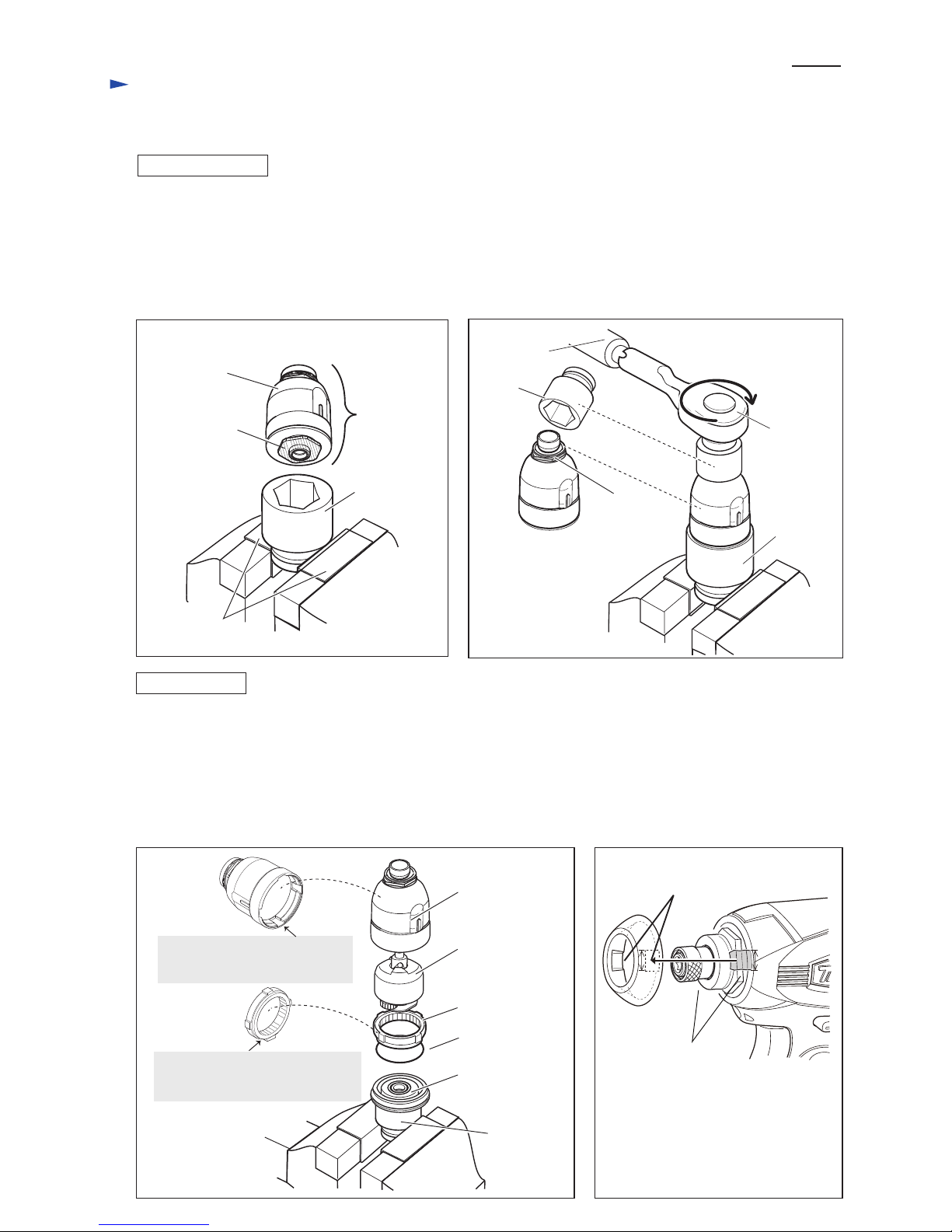
(1) Remove Hammer section by steps drawn in Fig. 2 to Fig. 7.
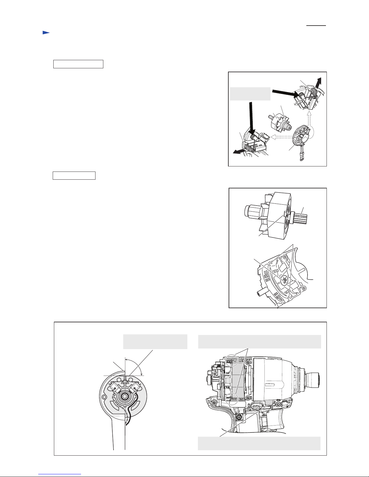
(2) Release tail of each Torsion spring from Carbon brushes and
hook these tails into the grooves around the edges of Brush holder.
(Fig. 12)
(3) Keep Carbon brushes apart from the commutator of Armature. (Fig. 12)
(4) Hold the coils of Torsion springs not to be removed, and pull out
Armature and Yoke unit together from Brush holder complete.
(Fig. 12)
Take the disassembling step in reverse.
Note: • When passing Armature through Yoke unit, make sure that
the notch on Yoke unit is positioned on Armature drive end.
(Fig. 13)
Because Armature is attracted to magnet of Yoke unit,
be careful to hold them not to pinch fingers and prevent the coils
against damage.
• When assembling the motor section to Bearing box complete,
insert Armature drive end into Internal gear 51 engaging with
Spur gears 22 . (Figs. 13 and 1)
• When the assembled sections (Hammer section, motor section and
Brush holder section) is set on Housing set (L), fit the projection
of the housing into the notch on Yoke unit. (Figs. 13 and 6)
• Be sure to check the following positions as drawn in Fig. 14.
(1) Flat portion of Brush holder complete
(2) Ribs on Housing set (L)
(3) Projection on Hammer case complete
P5/ 11
Repair
Carbon brush
Hold the coils of
Torsion springs.
Carbon
brush
Armature
drive end
Notch on
Yoke unit
Projection on
Housing set (L)
Brush holder
complete
Armature
Yoke unit
90
°
(1) flat portion of
Brush holder complete
Brush holder complete
viewed from the rear side
(2) Yoke unit end has to be attached to the right side
of the ribs of Housing set (L).
(3) Projection of Hammer case complete has to be
placed here that is the closest position to Switch.
edge of Housing set (L)
Ribs for
Yoke unit
(Re: Fig. 14)