Makita MAKSTAR BTL060RF Manual

Models No.
Description
PRODUCT
CONCEPT AND MAIN APPLICATIONS
Specification
P 1/ 9
L
H
W
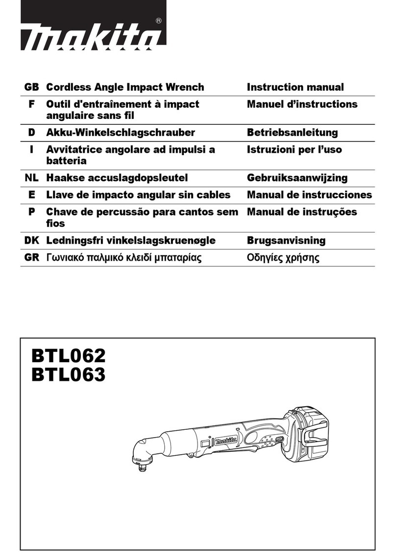
BTL060/ BTL061
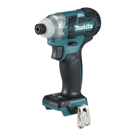
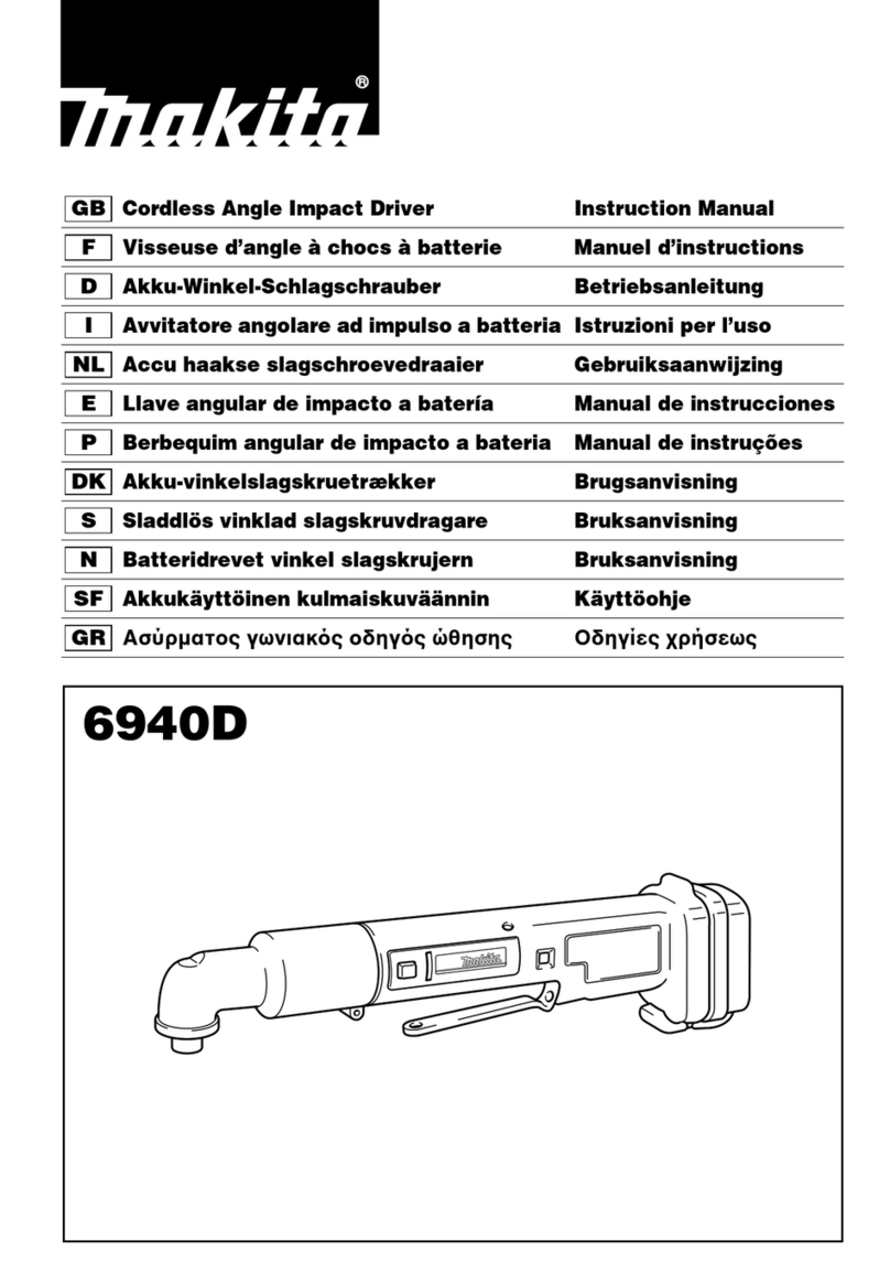
Cordless Angle Impact Drivers 14.4V/ 18V
Models BTL060 and BTL061 have been developed as advanced
models of 6940D.
Additionally to the same high fastening performance and
compact angle head as Model 6940D, feature soft grip and
LED job light for more maneuverability in tight places.
This product is available in the following variations.
BTL060 BTL061
Model
Specifications
Dimensions: mm (")
Width (W)
Height (H)
Length (L) 387 (15-1/4)
97 (3-13/16) 116 (4-9/16)
78 (3-1/16)
BTL060 BTL061
BTL060
BTL061
Battery
No load speed: min.-1=rpm
Impacts per min.: min.-1=ipm
Max. fastening torque: N.m [kgf.cm] (in.lbs)
Capacities
Electric brake
Reverse switch
Net weight: kg (lbs)
Variable speed control by trigger
Capacity: Ah
Cell
Voltage: V 1814.4
0 - 2,000
0 - 3,000
60 [610] (530)
Standard bolt
High tensile bolt
Machine screw
Driving shank
M4 - M12 (5/32 - 7/16")
M4 - M8 (5/32 - 5/16")
Coarse thread screw 22 - 75mm (7/8 - 2-31/32")
M4 - M8 (5/32 - 5/16")
Yes
Yes
Yes
1.6 (3.5)*11.7 (3.7)*2
3.0
Li-ion
110 120
6.35mm (1/4") Hex
Max output (W)
*1: with Battery BL1430 *2: with Battery BL1830
TECHNICAL INFORMATION
22
with DC18RA
LED Job light
See next page for Standard equipment and Optional accessories.
Yes
Charging time: min.
All models also include the accessories listed in "Standard equipment" on next page.
BTL060
BTL060RFE
BTL060Z
BTL060 BL1430
(Li-ion 3.0Ah) DC18RA
No No No
Model No. type quantity Charger
Yes
No
Plastic
carrying case Offered to
All countries
North America
All countries except North America
2
BTL060RF 1
1
No
Battery Battery
cover
BTL061
BTL061RFE
BTL061Z
BTL061 BL1830
(Li-ion 3.0Ah) DC18RA
No No No
Model No. type quantity Charger
Yes
No
Plastic
carrying case Offered to
All countries
North America
All countries except North America
2
BTL061RF 1
1
No
Battery Battery
cover

P 2/ 9
Standard equipment
Optional accessories
Sockets
Bits
Socket adapter
Straight attachment
Ratchet attachment
Fast charger DC18RA
Charger DC24SA (for North America only)
Charger DC24SC (for all countries except North America)
Battery BL1430 (for BTL060)
Battery BL1830 (for BTL061)
Note: The standard equipment for the tool shown above may differ by country.
Phillips bit 2-45 ................ 1
Belt clip ............................ 1

P 3/ 9
Repair
[1] NECESSARY REPAIRING TOOLS
CAUTION: Remove the battery from the machine for safety before repair/ maintenance,
in accordance with the instruction manual!
1R005 Retaining ring R pliers RT-2N Removing/installing Retaining ring R-26
Code No. Description Use for
Removing Ball bearings and Zerol bevel gear 131R269 Bearing extractor
1R291 Retaining ring S and R pliers
Removing/installing Retaining rings S-10 and R-28
[3] -1. Angle Head Complete
1R291
Retaining ring S and R pliers
Removing/installing Ring spring 11
[3] -2. Bit holder Section
1R288 Screwdriver magnetizer Removing Steel ball 4.8
1R346 Center attachment for 1R045
1R045 Gear extractor, large Disassembling/assembling Hammer section
[3] -3. Hammer Section
[2] LUBRICATION and ADHESIVE APPLICATION
Apply Makita grease N. No.2 to the portions designated with the black triangle
to protect parts and product from unusual abrasion. (Fig. 1)
LUBRICATION
Fig. 1
Item No. Description Lubricant Portion to lubricate
Spindle complete Surface that contacts Anvil
Whole surface
Steel ball 4.8 (2 pcs)
34
35 39
Anvil Surface that contacts Sleeve 15
Surface of the hole that contacts Zerol bevel gear 13
Whole surfaceSteel ball 3.5 (22 pcs)
23
25
Teeth portion (Apply about 1.5g.)Internal gear 69
30
Makita grease
N. No.2
Angle head complete Gear room for two Zerol bevel gears (Apply about 1.5g.)
13
Spindle
Zerol bevel gear 13
Zerol bevel gear 13
Sleeve 15
Hammer
23

Repair
P 4/ 9
[3] -1. Angle Head Complete
[3] DISASSEMBLY/ASSEMBLY
DISASSEMBLING
1) Angle head complete can be removed from Housing simply by unscrewing (+) Hex bolt M5x30.
Note: If the overlapping portion of Angle head complete is deformed from abuse or a fall, Angle head complete cannot
be removed from Housing by hand. In this case, remove it while expanding the slit between the bolt holes
with a slotted screwdriver. (Fig. 2)
2) Remove Retaining ring R-26 using 1R005.
3) By striking Angle head complete straight against a flat surface of work bench or the like, the following parts can be
removed as an assembly (Fig. 3):
Zerol bevel gear 13, Ball bearing 6000, Sleeve 10, Ball bearing 6000LLB, Retaining ring S-10
4) Remove Retaining ring S-10 using 1R291, then two Ball bearings using 1R269.
5) Remove Rubber ring 32 from Angle head complete, then remove Retaining ring R-28 using 1R291.
6) Spindle section can now be removed by tapping Angle head complete.
Note: Spindle section cannot be removed if Angle head complete is deformed from abuse or a fall.
In this case, attach an appropriate bit on Angle head complete, then clamp the bit securely in a vise.
Spindle section can now be removed by tapping Angle head complete with plastic hammer as illustrated in Fig..4.
7) Spindle section can be disassembled as described in Fig. 5.
Fig. 3 Fig. 4Fig. 2
Angle head complete
bitvise
bolt hole
Angle head complete
assembly consisting of
Zerol bevel gear 13, etc
Angle head complete
Fig. 5
Zerol bevel gear 13
Ball bearing 6001DDW
Insert an awl between the teeth of Spindle
into Ring spring 9.
Note: Insert into the space on the opposite
side of the ends of Ring spring 9.
Hook Ring spring 9 by moving the awl
in the direction of the arrow.
Note: Ring spring 9 will be deformed when
removed from Spindle.
Be sure to use new one for assembling
1) Remove Ring spring 9 from Spindle
by taking the following steps:
2) Remove Zerol bevel gear 13 from Spindle
by striking Spindle straight against a flat
surface of work bench or the like.
If cannot be removed, remove together with
Ball bearing 6001DDW using 1R269
as illustrated below.
ends of Ring spring 9
teeth of Spindle
Zerol bevel gear 13
Ball bearing 6001DDW
Spindle 1R269
Repair
P 5/ 9
[3] -2. Bit Holder Section
[3] DISASSEMBLY/ASSEMBLY
DISASSEMBLING
Open the ends of Ring spring 11 using 1R291 while pressing Ring spring 11 with the thumb of the other hand
in order not to allow Flat washer 12 and Compression spring 13 to pop out.
By lifting up Ring spring 11 carefully as described in Fig. 6, the following parts can be removed:
Flat washer 12, Compression spring 13, Sleeve, Steel ball 3.5 (2 pcs)
Fig. 6
Fig. 9
[3] -3. Hammer Section
DISASSEMBLING
1) Remove Angle head complete by unscrewing (+) Hex bolt M5x30.
2) Remove Housing R by unscrewing eight 4x18 Tapping screws. (Fig. 7)
3) Remove Switch lever from Housing L, then by levering up DC Motor with slotted screwdriver as illustrated in Fig. 8,
the following parts can be removed from Housing L as an assembly: DC Motor, Gear section, Hammer section
4) The assembly can be disassembled by hand except Hammer section. (Fig. 9)
Fig. 7 Fig. 8
1R291
Steel ball 3.5
(2 pcs)
Sleeve
Compression
spring 13
Flat washer 12
Lift up the side opposite to the ends
of Ring spring 11 in the direction
of the arrow with index finger.
Ring spring 11
Tapping screw 4x18 (8 pcs)
Switch lever
DC Motor Gear section Hammer section
Hammer section
Sleeve 15
Flat washer 15
Flat washer 12
Internal gear 69 Ring 32 Spur gear 29 (3 pcs) Rubber washer 21Anvil
DC Motor

Repair
P 6/ 9
[3] DISASSEMBLY/ASSEMBLY
DISASSEMBLING
5) Attach 1R045 and 1R346 to Hammer, and pull Hammer towards 1R346 as illustrated to left in Fig. 10.
Then remove Steel ball 4.8 (2 pcs) from Spindle using screwdriver magnetized with 1R288.
Hammer section can now be disassembled as illustrated to right in Fig. 10.
Note: When detaching 1R045 and 1R346 from Hammer, be sure to turn over Hammer section to put Hammer on the
bottom side. Otherwise, Steel ball 3.5 (22 pcs) in Hammer will scatter around.
Fig. 10
ASSEMBLING
Do the reverse of the disassembling steps
Note 1: As illustrated to right in Fig. 11, the groove inside Hammer is designed to have a space equivalent to
one half of a Steel ball 3.5 when twenty-two Steel balls are correctly installed.
Fig. 11
Note 2: Flat washer 15 is not reversible
when assembled to Anvil.
The center hole of Flat washer 15
is beveled on on face, and plain
on the other.
Be sure to place the beveled face
on the T-end of Anvil. (Fig. 12)
[3] -3. Hammer Section (cont.)
1R045
1R346
Hammer
Ball bearing 6000
Spindle complete
Steel ball 4.8
(2 pcs)
screwdriver magnetized
with 1R288
Hammer
Ball bearing 6000
Spindle complete
Compression spring 22
Flat washer 20
Steel ball 3.5 (22 pcs)
Washer 10
Hammer
Hammer
Steel ball 3.5
(22 pcs)
space equivalent to
one half of a Steel ball 3.5
Steel ball 3.5
(22 pcs)
Fig. 12
T-end of Anvil
beveled beveled
[Cross section]
Flat washer 15 T-end of Anvil Flat washer 15

Repair
P 7/ 9
[3] DISASSEMBLY/ASSEMBLY
ASSEMBLING
Note 3: Internal gear 69 is reversible when assembled to Housing L
although there is a notch on one of the two protrusions.
Note 4: When assembling DC Motor to Gear section, do not force
the pinion gear of DC Motor into Gear section.
Be sure to insert the pinion gear into three Spur gears (Spur gear 29)
while engaging them. Otherwise, DC Motor will run slower with
occasional siren-like noise. In this case, disassemble the machine
again, and insert the pinion gear correctly as described above.
Note 5: Do not forget to put the following parts in place before assembling
Housing R to Housing L (Fig. 13): Cushion, Pin 1.5, Rubber pin 5
[3] -3. Hammer Section (cont.)
Fig. 13
Cushion
Rubber pin 5
Pin 1.5

P 8/ 9
Fig. D-1
Fig. D-2
Circuit diagram
Terminal Switch
LED Circuit
DC Motor
Color index of lead wires' sheath
Black
Red
Protective tubeConnector
red marking
Wiring diagram
[1] Assembling LED Circuit to Housing L
Fig. D-3
[2] Connecting Lead Wires to DC Motor
bond
Lead wire
outside of Housing L
Assemble LED Circuit to Housing L
as illustrated below.
LED Circuit
groove
Route Lead wires of LED Circuit
through these grooves.
Lead wires of LED Circuit
must be tight in this portion.
DC Motor
red marking
Receptacle
to Terminals of Switch
Receptacles on Lead wires from
Terminals of Switch must be connected
to DC Motor as illustrated to right.

P 9/ 9
Fig. D-4
Wiring diagram
[3] Before Connecting Switch to LED Circuit
Fig. D-5
[3] After Connecting Switch to LED Circuit
Lead wire holder
Fix Lead wires with Lead wire holder.
Do not cross Lead wires under Switch.
Note: Be careful not to pinch Lead wires between
Switch and the inside wall of Housing L.
Pass Lead wires through the grooves.
Route Lead wires in this space.
Note: Be careful not to put Lead wires on the rib.
Connect Flag connectors with Terminal and Switch
as illustrated to right.
rib rib
groove Housing L
Terminal
Switch DC Motor
Terminal
Switch DC Motor
Put Connectors on Lead wires.
Put the slack portion of LED Circuit lead wires in this space.
Pass Lead wires between the pin and the inside wall of Housing L.
Put the slack portion of Switch lead wires in this space.
Note: Be careful not to put Lead wires on the rib.
Also be careful not to allow Lead wires to contact the edge
of DC Motor or Terminal of DC Motor.
Flag connector
Terminal
pole mark (+)
pole mark (-)
Switch
black
red
M1 M2
Connector
Terminal of DC Motor
pin
This manual suits for next models
7
Table of contents
Other Makita Impact Driver manuals

Makita
Makita TD003GZ User manual

Makita
Makita 6934FD User manual

Makita
Makita BTD150 User manual

Makita
Makita TD0101 User manual

Makita
Makita TD020D User manual

Makita
Makita TD021DSE User manual

Makita
Makita DLX2423TJ User manual

Makita
Makita DTD136 User manual

Makita
Makita XT1501 User manual

Makita
Makita XDT12Z User manual

Makita
Makita LXDT04 User manual

Makita
Makita 6935FD User manual

Makita
Makita MAKSTAR BTW251 Series Quick start guide

Makita
Makita TW0200 Quick start guide

Makita
Makita TD127D User manual

Makita
Makita TD001G User manual

Makita
Makita BTD130F User manual

Makita
Makita 6903VD User manual

Makita
Makita DTP141RMJ User manual

Makita
Makita 6914D User manual